49
©2013IEEE Electromagnetic Compatibility Magazine – Volume 2 – Quarter 3
C
oincidentally, all three papers in this issue are related totime-domain pulsed EMI. For those of you who are working in the areas of electrostatic discharge (ESD) event detec-tion, effect of ESD on integrated circuits (ICs) and lightning surge protection, you will truly enjoy reading these papers.
The first paper, “Pulsed Hertzian Dipole Radiation and Electrostatic Dis-charge Events in Manufacturing,” is contributed by Timothy J. Maloney of Intel Corporation. It is well known that ESD events monitoring in the factory is crucial to minimize a destructive Charged Device Model (CDM) ESD event in semiconductor manufacturing. Based on his earli-er work in formulation of pulsed dipole radiation using the Laplace Transform, Tim has demonstrated monocycle pulse can be made very reproducibly by augmenting a Transmission Line Pulse (TLP) system with two high-speed directional couplers. This artificial antenna pulse radiation is useful for evaluating the performance of a CDM ESD event detector in the factory.
The next paper “Effect of ESD on Complex Programmable Logic Device and Field Programmable Gate Arrays,” is authored by a group of researchers from Bangalore, India. They are Rajashree Narendra of BNM Institute of Technology, M. L. Sudheer of UVCE and D. C. Pande of LRDE. With the trends of thinner gate oxides, complex designs with multiple power supplies, larger chip capacitance and faster circuit operation, advanced ICs such as Complex Programmable Logic Device
(CPLD) and Field Programmable Gate Arrays (FPGA) are highly sensi-tive to ESD. Through practical case studies, they have shown that the FPGA module in an electronic product, which is damaged during ESD testing, has created a defect in the power supply that results in subse-quent failure in the CPLD module. Hence, protection design cannot be overlooked to ensure ESD immunity of these ICs.
The last paper, “Choosing the Appropriate Gas Discharge Tubes for Avionics Lightning Protection,” is submitted by Clay A. McCreary of Rockwell Collins Inc and Brian A. Lail of Florida Institute of Technol-ogy. Gas Discharge Tubes (GDTs) are commonly used to reduce the severity of lightning transients allowing secondary protection to the downstream circuits. The authors share with us why some GDTs do not operate according to the impulse spark-over voltage ratings in their datasheet. Predictable impulse spark-over voltage is important because downstream components being protected by the GDT are typically capable of tolerating short transients. If the GDT does not comply with the rated impulse spark-over voltage, protection of the downstream components cannot be guaranteed.
EMC encompasses a very diverse range of topics and thus this col-umn must reflect this diversity. I look forward to receiving more prac-tical papers and application notes with broader coverage of various topics. If you are interested in submitting a paper to this column, please submit the paper directly to me by email: [email protected].
Practical Papers, Articles
and Application Notes
Kye Yak See, Technical Editor
Pulsed Hertzian Dipole Radiation and Electrostatic
Discharge Events in Manufacturing*
Timothy J. Maloney, Intel Corporation, 2200 Mission College Blvd., SC9-09, Santa Clara, CA 95054 USA
tel.: 408-765-9389 e-mail: [email protected]
Abstract – A destructive Charged Device Model electrostatic discharge event can happen in semiconductor manufacturing and should be detectable from radiation that results from col-lapse of an electric dipole. The analytically describable radia-tion field pulse of CDM can be readily produced with a new instrument that creates dipole collapse at will. A coaxial monopole E-field antenna’s transfer function gives the anten-na siganten-nal in near-field, and experiments compare well with theory. A major feature of the antenna response to this field pulse is a bipolar “monocycle” pulse. A transmission
line-based synthetic monocycle pulser, for characterizing anten-na-driven ESD detectors, can be built and is described.
I. Introduction
A Charged Device Model (CDM) electrostatic discharge (ESD) stress results when a charged component creates equal and opposite mirror charge in a ground plane, followed by collapse of the electric dipole in a current pulse when the affected pin touch-es ground. In recent years, workers have sought to measure such ESD events or monitor them in the factory by detecting radiated fields with a nearby antenna [1, 2]. This has achieved some static monitoring and control, but it has not been clear how to interpret the measured antenna waveforms in terms of the more familiar
50
©2013IEEE Electromagnetic Compatibility Magazine – Volume 2 – Quarter 3 component CDM current waveforms and charge quantities. Also,factory tools are being outfitted with compact CDM ESD threshold detectors, fed by antennas situated near the possible source of ESD events. This motivates us to relate the yes/no thresholds of these electronic boxes, at a particular setting, to the expected properties of the antenna pulses coming in.
The author’s recent paper in this magazine [3] described, in analytic form for free space, the small collapsing dipole pulses common to CDM events. These are pulsed Hertzian dipoles, much as long described in the literature for pulsed transmitting antennas but using a unique pole-zero treatment that captures all near and far fields (static field, induction field, radiated field) at once. This for-mulation, using complex frequencies to describe the current and field pulses, allows inversion to the time domain through the inverse Laplace Transform, and thus provides us with the basic building blocks of the CDM fields. Then we need to find the expected response of an antenna to that field. Our example will be a simple E-field antenna with a straightforward transfer function for the expected signal into a 50 ohm scope. As we will see, this pulse shape has been found to agree well with experiments, whereby an artificial CDM event produces a monitored current pulse and anten-na siganten-nal simultaneously. The antenanten-na is placed nearby (15 cm, for example), as it would typically be in factory equipment. Given the propagation time to the antenna location (500 psec) and the expect-ed speexpect-ed of the event (nanosecond or sub-nanosecond pulses, rise times down to 100 psec or less), both the near fields and far field contribute, but this is all captured in one pole-zero expression as in [3], employable in both time and frequency domains.
Once the overall behavior of antenna signals for CDM is described, computed, and measured, we need to measure the effect of such signals on the compact ESD detector box, the yes/ no threshold detector, at a particular setting. Does triggering pri-marily depend on peak-to-peak voltage, as expected? What is the influence of pulse speed, and is signal dispersion in the cable important? We will see how to replace the artificial air discharge CDM pulse and antenna with a highly reproducible synthetic pulse that has much more dynamic range and is easier to use. Starting with a familiar Transmission Line Pulse (TLP) system and using some expedient passive circuits, one can synthesize fast bipolar pulses resembling the E-field monopole antenna (made from coax-ial cable and little else) response to CDM field pulses.
II. Pulsed Field Theory and Pulse Generators
1. Pulsed Hertzian Dipole Field Theory
Reference [3] is suitable for adopting its notation, coordinate sys-tem, field equations, and series RLC circuit models. Complex fre-quency s=σ+jω will appear often. The focus of [3] is calculation of the pulsed electric dipole fields with extension to the complemen-tary magnetic dipole as described therein. In [3], expressions for all electric dipole fields, near and far, electric and magnetic, radi-al, azimuthal and polar, are derived (these are summarized in the Appendix). We are primarily interested in the “equatorial” polar E field Eθ, aligned with the current source and electric dipole moment vector (z-direction), as this induces the largest signal in the antenna (Figure 1). In the s domain,
(1)
where the polar angle θ=p/2 at the equator, r is the distance from the source, c is the speed of light, dl is the length of the dipole. As explained in [3], the three terms describe the static field, induction field, and radiation field in the complex frequency domain. We will describe the current pulse I(s) once we see an example of a cur-rent pulse produced by dipole collapse.
The E-field of an electric dipole is the only field to which our E-field antenna is sensitive; the polar field Eθ is the only E-field at the equator, as the radial field Er vanishes there. Er depends only on static and inductive terms. Meanwhile, the associated magnet-ic field Hφ is azimuthal and involves only the induction and far-field radiation terms. These facts are well established in standard text-books [4-6], but [3] offers a rare glimpse into the s-domain formula-tion (instead of setting s=jω) and thus allows direct access to the pulsed field solutions that we need for CDM.
2. CDM-like Pulse Source and Model
A conceptual view of a generator of CDM-like pulses is shown in Figure 2. A charged plate with a spring loaded pogo pin comes down on a pedestal at the end of the center conductor of a 50-ohm coax line with its shield on the ground plane. The field created between the charge plate and the ground plate then col-lapses and the current is detected by the 50-ohm scope connec-tion. Note that any CDM spark resistance is in series with the 50 ohms, which raises the damping factor, simplifies the pulse, and makes ringing unlikely.
The top trace in Figure 3 shows the current pulse resulting from -100V applied to a pulse generator built as in Fig. 2, an instrument that has come to be known as the Charged Device Model Event Simulator (CDMES) [7]. A 3 GHz oscilloscope was used; the pulse has its peak and strongest derivatives in the first few hundred picoseconds.
2
II. Pulsed Field Theory and Pulse
Generators
1. Pulsed Hertzian Dipole Field Theory
Reference [3] is suitable for adopting its notation, coordinate system, field equations, and series RLC circuit models. Complex frequency s=σ+jω will appear often. The focus of [3] is calculation of the pulsed electric dipole fields with extension to the complementary magnetic dipole as described therein. In [3], expressions for all electric dipole fields, near and far, electric and magnetic, radial, azimuthal and polar, are derived (these are summarized in the Appendix). We are primarily interested in the “equatorial” polar E-field Eθ, aligned with the currentsource and electric dipole moment vector (z-direction), as this induces the largest signal in the antenna (Figure 1). In the s-domain,
c r s
s dl sr s I s
E = ⋅ +
τ
+τ
τ
=πε
θ
θ (1 ),
4 sin ) ( )
( 2 2
3 0
, (1)
where the polar angle θ=π/2 at the equator, r is the distance from the source, c is the speed of light,dlis the length of the dipole. As explained in [3], the three terms describe the static field, induction field, and radiation field in the complex frequency domain. We will describe the current pulse I(s) once we see an example of a current pulse produced by dipole collapse.
The E-field of an electric dipole is the only field to which our E-field antenna is sensitive; the polar field Eθis the only E-field at the equator, as the radial field
Er vanishes there. Er depends only on static and inductive terms. Meanwhile, the associated magnetic field Hφ is azimuthal and involves only the induction
and far-field radiation terms. These facts are well established in standard textbooks [4-6], but [3] offers a rare glimpse into the s-domain formulation (instead of setting s=jω) and thus allows direct access to the pulsed field solutions that we need for CDM.
2. CDM-like Pulse Source and Model
A conceptual view of a generator of CDM-like pulses is shown in Figure 2. A charged plate with a spring loaded pogo pin comes down on a pedestal at the end of the center conductor of a 50-ohm coax line with its shield on the ground plane. The field created between the charge plate and the ground plate then collapses and the current is detected by the 50-ohm scope connection. Note that any CDM spark resistance is in series with the 50 ohms, which raises the dampingfactor, simplifies the pulse, and makes ringing unlikely.
Figure 1. Experimental arrangement of CDM electric dipole initial source pand 6 mm coaxial antenna.
Figure 2. CDM pulse generator. Charge plate probe hits pedestal and dipole collapses, with current pulse and dipole radiation.
The top trace in Figure 3 shows the current pulse resulting from -100V applied to a pulse generator built as in Fig. 2, an instrument that has come to be known as the Charged Device Model Event Simulator (CDMES) [7]. A 3 GHz oscilloscope was used; the pulse has its peak and strongest derivatives in the first few hundred picoseconds.
to 50
Ω
scope
p
15 cm
6 mm “monopole”
antenna on 50
Ω
cable
10 Meg
Charge plate
Coax to 50 ohm scope
+V
Ground plate
+++++ +++++
- - -
-Figure 1. Experimental arrangement of CDM electric dipole initial source p and 6 mm coaxial antenna.
2
II. Pulsed Field Theory and Pulse
Generators
1. Pulsed Hertzian Dipole Field Theory
Reference [3] is suitable for adopting its notation, coordinate system, field equations, and series RLC circuit models. Complex frequency s=σ+jω will appear often. The focus of [3] is calculation of the pulsed electric dipole fields with extension to the complementary magnetic dipole as described therein. In [3], expressions for all electric dipole fields, near and far, electric and magnetic, radial, azimuthal and polar, are derived (these are summarized in the Appendix). We are primarily interested in the “equatorial” polar E-field Eθ, aligned with the currentsource and electric dipole moment vector (z-direction), as this induces the largest signal in the antenna (Figure 1). In the s-domain,
c r s
s dl sr s I s
E = ⋅ +
τ
+τ
τ
=πε
θ
θ (1 ),
4 sin ) ( )
( 2 2
3 0
, (1)
where the polar angle θ=π/2 at the equator, r is the distance from the source, c is the speed of light,dlis the length of the dipole. As explained in [3], the three terms describe the static field, induction field, and radiation field in the complex frequency domain. We will describe the current pulse I(s) once we see an example of a current pulse produced by dipole collapse.
The E-field of an electric dipole is the only field to which our E-field antenna is sensitive; the polar field Eθis the only E-field at the equator, as the radial field
Er vanishes there. Er depends only on static and inductive terms. Meanwhile, the associated magnetic field Hφ is azimuthal and involves only the induction
and far-field radiation terms. These facts are well established in standard textbooks [4-6], but [3] offers a rare glimpse into the s-domain formulation (instead of setting s=jω) and thus allows direct access to the pulsed field solutions that we need for CDM.
2. CDM-like Pulse Source and Model
A conceptual view of a generator of CDM-like pulses is shown in Figure 2. A charged plate with a spring loaded pogo pin comes down on a pedestal at the end of the center conductor of a 50-ohm coax line with its shield on the ground plane. The field created between the charge plate and the ground plate then collapses and the current is detected by the 50-ohm scope connection. Note that any CDM spark resistance is in series with the 50 ohms, which raises the dampingfactor, simplifies the pulse, and makes ringing unlikely.
Figure 1. Experimental arrangement of CDM electric dipole initial source pand 6 mm coaxial antenna.
Figure 2. CDM pulse generator. Charge plate probe hits pedestal and dipole collapses, with current pulse and dipole radiation.
The top trace in Figure 3 shows the current pulse resulting from -100V applied to a pulse generator built as in Fig. 2, an instrument that has come to be known as the Charged Device Model Event Simulator (CDMES) [7]. A 3 GHz oscilloscope was used; the pulse has its peak and strongest derivatives in the first few hundred picoseconds.
to 50
Ω
scope
p
15 cm
6 mm “monopole”
antenna on 50
Ω
cable
10 Meg
Charge plate
Coax to 50 ohm scope
+V
Ground plate
-51
©2013IEEE Electromagnetic Compatibility Magazine – Volume 2 – Quarter 3 We need a current function I(s) to approximate the pulse from this
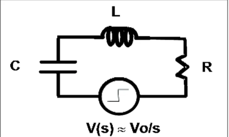
artificial CDM source. With a polynomial-based pole-zero expres-sion, the fields can be computed using Heaviside inversion of the Laplace Transform [3]. The two-pole series RLC response to a step function is a favorite way to model a CDM pulse current [3] that occurs through capacitive discharge such as in Fig. 2. This is even the case with human body model (HBM) currents [8]. One
can avoid field singularities by putting enough polynomial order in the denominator of Eθ(s). We use high-speed poles to model a step source with finite rise time for the spark, and then multiply the familiar RLC expression for the rest of I(s) [3].
Figure 4a shows a calculated current pulse that approximates the experimentally measured CDMES current pulse as shown in Fig. 3, up to the trailing “ledge” on the measured pulse. Four poles were used for the basic current pulse--two poles for the estimated 60 psec spark rise time and two more to capture the estimated RLC network (see Appendix), where R≈80 ohms (spark resistance + 50 ohms), L≈3 nH (probe inductance) and C≈1.66 pF (given by current integral from Fig. 3, although that includes the “ledge”). Then two more poles were added to capture the 3 GHz oscilloscope filtering, in accordance with models in [9]. With total charge reduced by 28% to adjust for the ledge, the current pulse then peaks at 0.49 amps, as calcu-lated in Mathematica using Heaviside expansion to produce the inverse Laplace Transform.
The resulting E-field, in Figure 4b, is calculated from (1) for a 15 cm distance. The dipole moment length dl is about 4.5 mm, so the Hertzian dipole approximation is still good. Note that the resulting E-field is very sharp, showing the influence of the derivatives, par-ticularly from the far-field (s2) term. Note also that while the CDM event is a collapsing dipole that starts out with nonzero static field and polarization (p in Fig. 1 is the initial dipole for a positive volt-age), it is easiest to calculate the transient as a step in the polar-ization that ends at a finite value. This value, of course, cancels the initial static field.
2
II. Pulsed Field Theory and Pulse
Generators
1. Pulsed Hertzian Dipole Field Theory
Reference [3] is suitable for adopting its notation, coordinate system, field equations, and series RLC circuit models. Complex frequency s=σ+jω will appear often. The focus of [3] is calculation of the pulsed electric dipole fields with extension to the complementary magnetic dipole as described therein. In [3], expressions for all electric dipole fields, near and far, electric and magnetic, radial, azimuthal and polar, are derived (these are summarized in the Appendix). We are primarily interested in the “equatorial” polar E-field Eθ, aligned with the currentsource and electric dipole moment vector (z-direction), as this induces the largest signal in the antenna (Figure 1). In the s-domain,
c r s
s dl sr s I s
E = ⋅ +
τ
+τ
τ
=πε
θ
θ (1 ),
4 sin ) ( )
( 2 2
3 0
, (1)
where the polar angle θ=π/2 at the equator, r is the distance from the source, c is the speed of light,dl is the length of the dipole. As explained in [3], the three terms describe the static field, induction field, and radiation field in the complex frequency domain. We will describe the current pulse I(s) once we see an example of a current pulse produced by dipole collapse.
The E-field of an electric dipole is the only field to which our E-field antenna is sensitive; the polar field Eθis the only E-field at the equator, as the radial field
Er vanishes there. Er depends only on static and inductive terms. Meanwhile, the associated magnetic field Hφ is azimuthal and involves only the induction
and far-field radiation terms. These facts are well established in standard textbooks [4-6], but [3] offers a rare glimpse into the s-domain formulation (instead of setting s=jω) and thus allows direct access to the pulsed field solutions that we need for CDM.
2. CDM-like Pulse Source and Model
A conceptual view of a generator of CDM-like pulses is shown in Figure 2. A charged plate with a spring loaded pogo pin comes down on a pedestal at the end of the center conductor of a 50-ohm coax line with its shield on the ground plane. The field created between the charge plate and the ground plate then collapses and the current is detected by the 50-ohm scope connection. Note that any CDM spark resistance is in series with the 50 ohms, which raises the dampingfactor, simplifies the pulse, and makes ringing unlikely.
Figure 1. Experimental arrangement of CDM electric dipole initial source pand 6 mm coaxial antenna.
Figure 2. CDM pulse generator. Charge plate probe hits pedestal and dipole collapses, with current pulse and dipole radiation.
The top trace in Figure 3 shows the current pulse resulting from -100V applied to a pulse generator built as in Fig. 2, an instrument that has come to be known as the Charged Device Model Event Simulator (CDMES) [7]. A 3 GHz oscilloscope was used; the pulse has its peak and strongest derivatives in the first few hundred picoseconds.
to 50
Ω
scope
p
15 cm
6 mm “monopole”
antenna on 50
Ω
cable
10 Meg
Charge plate
Coax to 50 ohm scope
+V
Ground plate
+++++ +++++ - - -
-Figure 2. CDM pulse generator. Charge plate probe hits pedestal and dipole collapses, with current pulse and dipole radiation.
3
Figure 3. Measured current (top) and antenna response (bottom) to E-field at 15 cm, using artificial CDM source; 2 nsec/division, 3 GHz scope. Setup as in Fig. 1, current polarity negative. Integrated current gives -166.4 pC of charge; 10x attenuation used.
We need a current function I(s) to approximate the pulse from this artificial CDM source. With a polynomial-based pole-zero expression, the fields can be computed using Heaviside inversion of the Laplace Transform [3]. The two-pole series RLC response to a step function is a favorite way to model a CDM pulse current [3] that occurs through capacitive discharge such as in Fig. 2. This is even the case with human body model (HBM) currents [8]. One can avoid field singularities by putting enough polynomial order in the denominator of Eθ(s). We use high-speed poles to model a step source with finite rise time for the spark, and then multiply the familiar RLC expression for the rest of I(s) [3].
Figure 4a shows a calculated current pulse that approximates the experimentally measured CDMES current pulse as shown in Fig. 3, up to the trailing “ledge” on the measured pulse. Four poles were used for the basic current pulse--two poles for the estimated 60 psec spark rise time and two more to capture the estimated RLC network (see Appendix), where R≈80 ohms (spark resistance + 50 ohms), L≈3 nH (probe inductance) and C≈1.66 pF (given by current integral from Fig. 3, although that includes the “ledge”). Then two more poles were added to capture the 3 GHz oscilloscope filtering, in accordance with
models in [9]. With total charge reduced by 28% to adjust for the ledge, the current pulse then peaks at 0.49 amps, as calculated in Mathematica using Heaviside expansion to produce the inverse Laplace Transform.
The resulting E-field, in Figure 4b, is calculated from (1) for a 15 cm distance. The dipole moment length
dl is about 4.5 mm, so the Hertzian dipole approximation is still good. Note that the resulting E-field is very sharp, showing the influence of the derivatives, particularly from the far-field (s2) term.
Note also that while the CDM event is a collapsing dipole that starts out with nonzero static field and polarization (p in Fig. 1 is the initial dipole for a positive voltage), it is easiest to calculate the transient as a step in the polarization that ends at a finite value. This value, of course, cancels the initial static field.
-166.4 pC
antenna,
15 cm
current
1.664 pF
125 mV
=Vp-p
-100V pulse
-0.496 A
max
52
©2013IEEE Electromagnetic Compatibility Magazine – Volume 2 – Quarter 3III. Calculated and Measured Antenna Pulses
The antenna used in these studies is a so-called monopole antenna made from coaxial cable. It is conceptually much as pictured in Fig. 1, aside from the Teflon cap over the 6 mm exten-sion of the coaxial center conductor. A signal is generated as the E-field induces an electric dipole in the tip, driving the 50-ohm load. A simple circuit model gives the transfer function of such an antenna [10], and it can be applied as in [3] to give measured voltage Vm as
(2)
for which Z0 is cable impedance (usually 50 ohms), Cm and Lm are the inductive and capacitive equivalents of the probe wire, and lm is the length of the probe wire. The field E-z=Eθ when maximum at
the equator, θ=p/2, as before. The experimental setup, Fig. 1, defines positive polarity. To get the sign right, it is helpful to con-sider the initial induced dipole on the antenna; for a positive dipole as shown, there will be a net negative charge integrated from cur-rent during the collapse. The transfer function for our 6 mm probe is found from values suggested by [10], with Lm=5.1 nH and with a little more capacitance (Cm=0.38 pF) due to the Teflon cap. Com-bining (1) and (2), the “s” terms now cancel, so the signal will have no dc component, as expected, and will be influenced by the two new poles from the antenna. Sure enough, the predicted antenna signal as in Figure 5 shows a response to the sharp pulse of Fig. 4b that is influenced by ringing of the antenna itself. The disper-sion along the coaxial cable (150 cm, RG-316) to the scope for
such fast pulses was a concern, but calculations based on time-honored analysis [11] show that such effects should be negligible, only a picosecond or two for this cable length.
Filtering by the 3 GHz scope bandwidth has been carried into the Fig. 5 calculations as well. The first two peaks of Fig. 5 match those of Fig. 3 almost exactly, with -48.1 mV and +72.6 mV calculat-ed in Fig. 5, versus +52 mV and -73 mV measurcalculat-ed in Fig. 3 (Fig. 3 being flipped because of the -100V). But the third peak is not as prominent in Fig. 3 as in Fig. 5. Even so, if a 200 psec RC filter is applied to the current function of Fig. 4a so that it has a longer and smoother tail (a little closer to the “ledge” feature of Fig. 3) as shown in Figure 6a, the result is the near-monocycle pulse of Fig-ure 6b. Now the current and antenna pulse are weaker than observed, although the total charge is correct. As there is consid-erable estimation of the model parameters of the antenna (particu-larly the effect of the antenna’s Teflon cap) and the discharge source, plus slight differences each time for air spark, plus effects of stray fields from the chargeup wire (which were reduced through careful design but are hard to eliminate completely), the agreement between theory and experiment is quite good. It’s a rare case of an ab initio pulsed field calculation followed by experiment. Such a crisp event as in Fig. 3 will not happen each time, but when it does, it’s a worst case, and its maximum current, field, and antenna signal can be associated with a maximum likeli-hood of device destruction if detected in the factory.
The main feature of the antenna pulse is the prominent “monocy-cle” pulse up front, present in Figs. 3-6, with its overall peak-to-peak voltage Vp-p found in the swing of the first two peak-to-peaks. We suspect that most CDM ESD detectors will be sensitive to Vp-p and now will show how to create easily reproducible monocycle pulses for detector characterization.
IV. Synthetic Antenna Pulses
1. Directional Couplers in the Time Domain
The expression for Vm, Eq. 2, converted to current given the 50 ohm scope input, indicates a small but finite current integral, given by the static charge on the antenna before collapse of the CDM dipole. This can just barely be discerned in Figs. 5-6 and looks like it may be lost in the noise in Fig 3. The antenna is much better as a sudden event detector and is not much of a static field meter! Accordingly, the monocycle pulse is nearly a
4
Figure 4a. Calculated CDM current pulse, 1 nsec full scale.Figure 4b. E-field pulse Eθat 15 cm from CDM current source as in Fig. 4a; 1 nsec full scale.
III. Calculated and Measured
Antenna Pulses
The antenna used in these studies is a so-called
monopole antenna made from coaxial cable. It is
conceptually much as pictured in Fig. 1, aside from
the Teflon cap over the 6 mm extension of the coaxial
center conductor. A signal is generated as the E-field
induces an electric dipole in the tip, driving the
50-ohm load. A simple circuit model gives the transfer
function of such an antenna [10], and it can be applied
as in [3] to give measured voltage V
mas
2 0
0
1
)
(
)
(
s
C
L
s
C
Z
s
C
Z
l
s
E
s
V
m m m
m m
z m
+
+
−
=
−
, (2)
for which Z
0is cable impedance (usually 50 ohms),
C
mand L
mare the inductive and capacitive
equivalents of the probe wire, and l
mis the length of
the probe wire. The field E
-z=E
θwhen maximum at
the equator,
θ
=
π
/2, as before. The experimental setup,
Fig. 1, defines positive polarity. To get the sign right,
it is helpful to consider the initial induced dipole on
the antenna; for a positive dipole as shown, there will
be a net negative charge integrated from current
during the collapse. The transfer function for our 6
mm probe is found from values suggested by [10],
with L
m=5.1 nH and with a little more capacitance
(C
m=0.38 pF) due to the Teflon cap. Combining (1)
and (2), the “s” terms now cancel, so the signal will
have no dc component, as expected, and will be
influenced by the two new poles from the antenna.
Sure enough, the predicted antenna signal as in Figure
5 shows a response to the sharp pulse of Fig. 4b that is
influenced by ringing of the antenna itself. The
dispersion along the coaxial cable (150 cm, RG-316)
to the scope for such fast pulses was a concern, but
calculations based on time-honored analysis [11]
show that such effects should be negligible, only a
picosecond or two for this cable length.
Figure 5. Calculated antenna response to E-field as in Fig. 4b, 15 cm from CDM source, 1.5 nsec full scale. Alignment as in Fig. 1.
Filtering by the 3 GHz scope bandwidth has been
carried into the Fig. 5 calculations as well. The first
two peaks of Fig. 5 match those of Fig. 3 almost
exactly, with -48.1 mV and +72.6 mV calculated in
Fig. 5, versus +52 mV and -73 mV measured in Fig. 3
(Fig. 3 being flipped because of the -100V). But the
third peak is not as prominent in Fig. 3 as in Fig. 5.
Even so, if a 200 psec RC filter is applied to the
current function of Fig. 4a so that it has a longer and
smoother tail (a little closer to the “ledge” feature of
Fig. 3) as shown in Figure 6a, the result is the
near-monocycle pulse of Figure 6b. Now the current and
antenna pulse are weaker than observed, although the
total charge is correct. As there is considerable
estimation of the model parameters of the antenna
(particularly the effect of the antenna’s Teflon cap)
and the discharge source, plus slight differences each
time for air spark, plus effects of stray fields from the
chargeup wire (which were reduced through careful
design but are hard to eliminate completely), the
agreement between theory and experiment is quite
good. It’s a rare case of an
ab initio
pulsed field
calculation followed by experiment. Such a crisp
event as in Fig. 3 will not happen each time, but when
it does, it’s a worst case, and its maximum current,
field, and antenna signal can be associated with a
maximum likelihood of device destruction if detected
in the factory.
0.2 0.4 0.6 0.8 1.0
0.1 0.2 0.3 0.4 0.5
amps
nanosec
Volts/cm
0.2 0.4 0.6 0.8 1.0
0.05 0.05 0.10 0.15 0.20 0.25 0.30
nanosec
0.2 0.4 0.6 0.8 1.0 1.2 1.4
40 20 20 40 60
nanosec
millivolts
Figure 4a. Calculated CDM current pulse, 1 nsec full scale.
amps
nanosec
4
Figure 4a. Calculated CDM current pulse, 1 nsec full scale.Figure 4b. E-field pulse Eθat 15 cm from CDM current source as in Fig. 4a; 1 nsec full scale.
III. Calculated and Measured
Antenna Pulses
The antenna used in these studies is a so-called
monopole antenna made from coaxial cable. It is
conceptually much as pictured in Fig. 1, aside from
the Teflon cap over the 6 mm extension of the coaxial
center conductor. A signal is generated as the E-field
induces an electric dipole in the tip, driving the
50-ohm load. A simple circuit model gives the transfer
function of such an antenna [10], and it can be applied
as in [3] to give measured voltage V
mas
2 0
0
1
)
(
)
(
s
C
L
s
C
Z
s
C
Z
l
s
E
s
V
m m m
m m
z m
+
+
−
=
−, (2)
for which Z
0is cable impedance (usually 50 ohms),
C
mand L
mare the inductive and capacitive
equivalents of the probe wire, and l
mis the length of
the probe wire. The field E
-z=E
θwhen maximum at
the equator,
θ
=
π
/2, as before. The experimental setup,
Fig. 1, defines positive polarity. To get the sign right,
it is helpful to consider the initial induced dipole on
the antenna; for a positive dipole as shown, there will
be a net negative charge integrated from current
during the collapse. The transfer function for our 6
mm probe is found from values suggested by [10],
with L
m=5.1 nH and with a little more capacitance
(C
m=0.38 pF) due to the Teflon cap. Combining (1)
and (2), the “s” terms now cancel, so the signal will
have no dc component, as expected, and will be
influenced by the two new poles from the antenna.
Sure enough, the predicted antenna signal as in Figure
5 shows a response to the sharp pulse of Fig. 4b that is
influenced by ringing of the antenna itself. The
dispersion along the coaxial cable (150 cm, RG-316)
to the scope for such fast pulses was a concern, but
calculations based on time-honored analysis [11]
show that such effects should be negligible, only a
picosecond or two for this cable length.
Figure 5. Calculated antenna response to E-field as in Fig. 4b, 15 cm from CDM source, 1.5 nsec full scale. Alignment as in Fig. 1.
Filtering by the 3 GHz scope bandwidth has been
carried into the Fig. 5 calculations as well. The first
two peaks of Fig. 5 match those of Fig. 3 almost
exactly, with -48.1 mV and +72.6 mV calculated in
Fig. 5, versus +52 mV and -73 mV measured in Fig. 3
(Fig. 3 being flipped because of the -100V). But the
third peak is not as prominent in Fig. 3 as in Fig. 5.
Even so, if a 200 psec RC filter is applied to the
current function of Fig. 4a so that it has a longer and
smoother tail (a little closer to the “ledge” feature of
Fig. 3) as shown in Figure 6a, the result is the
near-monocycle pulse of Figure 6b. Now the current and
antenna pulse are weaker than observed, although the
total charge is correct. As there is considerable
estimation of the model parameters of the antenna
(particularly the effect of the antenna’s Teflon cap)
and the discharge source, plus slight differences each
time for air spark, plus effects of stray fields from the
chargeup wire (which were reduced through careful
design but are hard to eliminate completely), the
agreement between theory and experiment is quite
good. It’s a rare case of an
ab initio
pulsed field
calculation followed by experiment. Such a crisp
event as in Fig. 3 will not happen each time, but when
it does, it’s a worst case, and its maximum current,
field, and antenna signal can be associated with a
maximum likelihood of device destruction if detected
in the factory.
0.2 0.4 0.6 0.8 1.0
0.1 0.2 0.3 0.4 0.5
amps
nanosec
Volts/cm
0.2 0.4 0.6 0.8 1.0
0.05 0.05 0.10 0.15 0.20 0.25 0.30
nanosec
0.2 0.4 0.6 0.8 1.0 1.2 1.4
40 20 20 40 60
nanosec
millivolts
Figure 4b. E-field pulse Eθ at 15 cm from CDM current source as in Fig. 4a; 1 nsec full scale.
Volts/cm
nanosec
4
Figure 4a. Calculated CDM current pulse, 1 nsec full scale.
Figure 4b. E-field pulse Eθat 15 cm from CDM current source as
in Fig. 4a; 1 nsec full scale.
III. Calculated and Measured
Antenna Pulses
The antenna used in these studies is a so-called monopole antenna made from coaxial cable. It is conceptually much as pictured in Fig. 1, aside from the Teflon cap over the 6 mm extension of the coaxial center conductor. A signal is generated as the E-field induces an electric dipole in the tip, driving the 50-ohm load. A simple circuit model gives the transfer function of such an antenna [10], and it can be applied as in [3] to give measured voltage Vmas
2 0
0 1
) (
) (
s C L s C Z
s C Z l s
E s V
m m m
m m
z m
+ +
− =
−
, (2)
for which Z0 is cable impedance (usually 50 ohms), Cm and Lm are the inductive and capacitive equivalents of the probe wire, and lmis the length of the probe wire. The field E-z=Eθ when maximum at
the equator,θ=π/2, as before. The experimental setup, Fig. 1, defines positive polarity. To get the sign right, it is helpful to consider the initial induced dipole on the antenna; for a positive dipole as shown, there will be a net negative charge integrated from current during the collapse. The transfer function for our 6 mm probe is found from values suggested by [10], with Lm=5.1 nH and with a little more capacitance
(Cm=0.38 pF) due to the Teflon cap. Combining (1) and (2), the “s” terms now cancel, so the signal will have no dc component, as expected, and will be influenced by the two new poles from the antenna. Sure enough, the predicted antenna signal as in Figure 5 shows a response to the sharp pulse of Fig. 4b that is influenced by ringing of the antenna itself. The dispersion along the coaxial cable (150 cm, RG-316) to the scope for such fast pulses was a concern, but calculations based on time-honored analysis [11] show that such effects should be negligible, only a picosecond or two for this cable length.
Figure 5. Calculated antenna response to E-field as in Fig. 4b, 15 cm from CDM source, 1.5 nsec full scale. Alignment as in Fig. 1.
Filtering by the 3 GHz scope bandwidth has been carried into the Fig. 5 calculations as well. The first two peaks of Fig. 5 match those of Fig. 3 almost exactly, with -48.1 mV and +72.6 mV calculated in Fig. 5, versus +52 mV and -73 mV measured in Fig. 3 (Fig. 3 being flipped because of the -100V). But the third peak is not as prominent in Fig. 3 as in Fig. 5. Even so, if a 200 psec RC filter is applied to the current function of Fig. 4a so that it has a longer and smoother tail (a little closer to the “ledge” feature of Fig. 3) as shown in Figure 6a, the result is the near-monocycle pulse of Figure 6b. Now the current and antenna pulse are weaker than observed, although the total charge is correct. As there is considerable estimation of the model parameters of the antenna (particularly the effect of the antenna’s Teflon cap) and the discharge source, plus slight differences each time for air spark, plus effects of stray fields from the chargeup wire (which were reduced through careful design but are hard to eliminate completely), the agreement between theory and experiment is quite good. It’s a rare case of an ab initio pulsed field calculation followed by experiment. Such a crisp event as in Fig. 3 will not happen each time, but when it does, it’s a worst case, and its maximum current, field, and antenna signal can be associated with a maximum likelihood of device destruction if detected in the factory.
0.2 0.4 0.6 0.8 1.0
0.1 0.2 0.3 0.4 0.5
amps
nanosec
Volts/cm
0.2 0.4 0.6 0.8 1.0
0.05 0.05 0.10 0.15 0.20 0.25 0.30
nanosec
0.2 0.4 0.6 0.8 1.0 1.2 1.4
40
20 20 40 60
nanosec millivolts
4
Figure 4a. Calculated CDM current pulse, 1 nsec full scale.
Figure 4b. E-field pulse Eθat 15 cm from CDM current source as
in Fig. 4a; 1 nsec full scale.
III. Calculated and Measured
Antenna Pulses
The antenna used in these studies is a so-called
monopole antenna made from coaxial cable. It is
conceptually much as pictured in Fig. 1, aside from
the Teflon cap over the 6 mm extension of the coaxial
center conductor. A signal is generated as the E-field
induces an electric dipole in the tip, driving the
50-ohm load. A simple circuit model gives the transfer
function of such an antenna [10], and it can be applied
as in [3] to give measured voltage V
mas
2 0
0
1
)
(
)
(
s
C
L
s
C
Z
s
C
Z
l
s
E
s
V
m m m
m m
z m
+
+
−
=
−
, (2)
for which Z
0is cable impedance (usually 50 ohms),
C
mand L
mare the inductive and capacitive
equivalents of the probe wire, and l
mis the length of
the probe wire. The field E
-z=E
θwhen maximum at
the equator,
θ
=
π
/2, as before. The experimental setup,
Fig. 1, defines positive polarity. To get the sign right,
it is helpful to consider the initial induced dipole on
the antenna; for a positive dipole as shown, there will
be a net negative charge integrated from current
during the collapse. The transfer function for our 6
mm probe is found from values suggested by [10],
with L
m=5.1 nH and with a little more capacitance
(C
m=0.38 pF) due to the Teflon cap. Combining (1)
and (2), the “s” terms now cancel, so the signal will
have no dc component, as expected, and will be
influenced by the two new poles from the antenna.
Sure enough, the predicted antenna signal as in Figure
5 shows a response to the sharp pulse of Fig. 4b that is
influenced by ringing of the antenna itself. The
dispersion along the coaxial cable (150 cm, RG-316)
to the scope for such fast pulses was a concern, but
calculations based on time-honored analysis [11]
show that such effects should be negligible, only a
picosecond or two for this cable length.
Figure 5. Calculated antenna response to E-field as in Fig. 4b, 15 cm from CDM source, 1.5 nsec full scale. Alignment as in Fig. 1.
Filtering by the 3 GHz scope bandwidth has been
carried into the Fig. 5 calculations as well. The first
two peaks of Fig. 5 match those of Fig. 3 almost
exactly, with -48.1 mV and +72.6 mV calculated in
Fig. 5, versus +52 mV and -73 mV measured in Fig. 3
(Fig. 3 being flipped because of the -100V). But the
third peak is not as prominent in Fig. 3 as in Fig. 5.
Even so, if a 200 psec RC filter is applied to the
current function of Fig. 4a so that it has a longer and
smoother tail (a little closer to the “ledge” feature of
Fig. 3) as shown in Figure 6a, the result is the
near-monocycle pulse of Figure 6b. Now the current and
antenna pulse are weaker than observed, although the
total charge is correct. As there is considerable
estimation of the model parameters of the antenna
(particularly the effect of the antenna’s Teflon cap)
and the discharge source, plus slight differences each
time for air spark, plus effects of stray fields from the
chargeup wire (which were reduced through careful
design but are hard to eliminate completely), the
agreement between theory and experiment is quite
good. It’s a rare case of an
ab initio
pulsed field
calculation followed by experiment. Such a crisp
event as in Fig. 3 will not happen each time, but when
it does, it’s a worst case, and its maximum current,
field, and antenna signal can be associated with a
maximum likelihood of device destruction if detected
in the factory.
0.2 0.4 0.6 0.8 1.0
0.1 0.2 0.3 0.4 0.5
amps
nanosec
Volts/cm
0.2 0.4 0.6 0.8 1.0
0.05 0.05 0.10 0.15 0.20 0.25 0.30
nanosec
0.2 0.4 0.6 0.8 1.0 1.2 1.4
40
20 20 40 60
nanosec
millivolts
Figure 5. Calculated antenna response to E-field as in Fig. 4b, 15 cm from CDM source, 1.5 nsec full scale. Alignment as in Fig. 1.
millavolts