ADAPTIVE EXERCISE EQUIPMENT
Final Design Review
06/05/2020
PRESENTED BY TEAM STEAM
Kalina Burns
Journey Martinson
Spencer Goodman
Jake Walejko
Mechanical Engineering Department
California Polytechnic State University
Abstract
This document outlines the senior design project carried out by a team of mechanical
Table of Contents
List of Figures 4
List of Tables 6
1.0 Introduction 7
2.0 Background 7
2.1 Customer Research 7
2.2 Product Research 9
2.3 Technical Research 11
3.0 Objectives 13
3.1 Problem Statement 13
3.2 Boundary Diagram 14
4.0 Concept Design 16
4.1 Brainstorming 16
4.2 Concept Modeling 16
4.3 Decision Matrices 19
4.4 Final Concept Design 19
4.5 Concept Prototypes 21
4.6 Potential Risks 22
5.0 Final Design 23
5.1 Final Design Explanation 23
5.2 Resistance Rack 24
5.3 Punching Bag 28
5.4 Pedaler Mount 29
5.5 Cost Analysis and Funding 30
6.0 Manufacturing Plan 31
6.1 Manufacturing Plan: Resistance Band Rack 31
6.2. Manufacturing Plan: Punching Bag 37
6.3. Manufacturing Plan: Adaptive Pedaler Mount 39
6.4 Outsourcing 42
7.0 Design Verification Plan 42
7.1 Engineering Specifications Testing 42
7.2 Testing Facility and Equipment Needs 43
9.0 Conclusions 46
Appendices 48
Appendix A - Technical Research 48
Appendix B - QFD House of Quality 51
Appendix C - Idea List 52
Appendix D - Decision Matrix 53
Appendix E - Gantt Charts 54
Appendix F - Design Hazard Checklist 56
Appendix G - Indented Bill of Materials 58
Appendix H - Design Verification/Testing Plan 59
Appendix I - Project Budget 64
Appendix J - Drawing Package 66
Appendix K - Revised Manufacturing Plan Resistance Rack 86
Appendix L - Operation Manual 95
Operation Manual: Resistance Rack 95
Operation Manual: Punching Bag 103
List of Figures
Figure 2.1. Achievement House Exercise Room Layout 9
Figure 3.1. Boundary Diagram 14
Figure 4.1. Concept Upper Body Elliptical 17
Figure 4.2. Concept Adaptable Rowing Machine 17
Figure 4.3. Concept Hand Pedaler 18
Figure 4.4. Concept Rope Pull Machine 18
Figure 4.5: Concept Resistance Band Pulling Device 19
Figure 4.6. Final Concept CAD Model 20
Figure 4.7. Resistance Band Rack Concept Prototype 21
Figure 4.8. Pedaler Adjustable Height Concept Prototype 22
Figure 5.1. Full Assembly of Final Design CAD Model 23
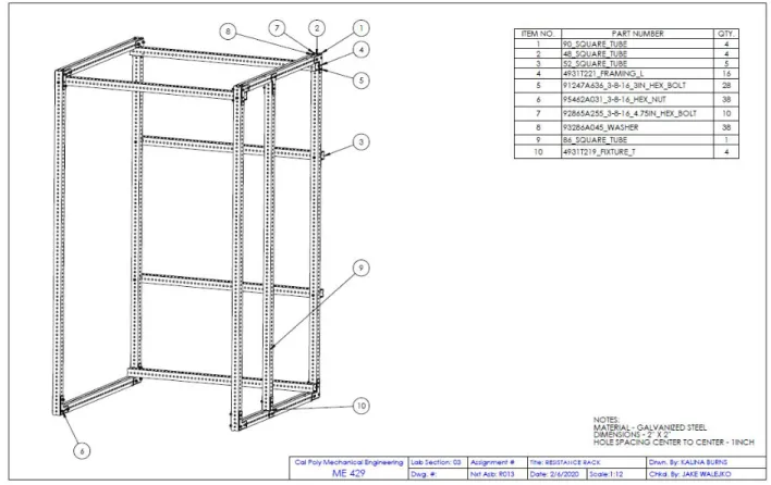
Figure 5.2.1. Resistance Rack Assembly Drawing 24
Figure 5.2.2. External Brackets 25
Figure 5.2.3. Alternative Design Comparison 25
Figure 5.2.4. Resistance Rack Deflection and Buckling Analysis 26
Figure 5.3.1. Assembly Model of Punching Bag Apparatus 28
Figure 5.4.1. Isometric View of the Pedaler Mount 29
Figure 5.4.2. Exploded Subassembly of the Pedaler Mount 30
Figure 6.1.1. Back Frame of Resistance Rack 32
Figure 6.1.2. Rack Assembly Joint A 32
Figure 6.1.3. Inserting 86” Post into Frame 33
Figure 6.1.4. Rack Assembly Joint B 33
Figure 6.1.6. Rack Assembly Joint D 34
Figure 6.1.7. Assembly of Final 52” Post to Frame 35
Figure 6.1.8. Assembling Ladder to Frame 35
Figure 6.1.9. Rack Assembly Joint C 36
Figure 6.1.10. Completed Resistance Rack 36
Figure 6.2.1. Model of Punching Bag and Rack Attachment Connectors. 38
Figure 6.2.2. Final Assembly of Punching Bag Attachment. 38
Figure 6.3.1. Wooden Platform Dimensions 39
Figure 6.3.2. Hole Locations in Wooden Platform (Side View) 40
Figure 6.3.3. Hole Locations in Aluminum Tubing (Side View) 40
Figure 6.3.4. Aluminum Tubing Bolted to Wooden Platform (Top View) 41
Figure 6.3.5. Bracket the Pedaler to the Platform 41
List of Tables
Table 2.1. Summary of Customer’s Needs and Wants
Table 2.2. Equipment Measurements
8
8
Table 2.3. Client Measurements
Table 2.4. Existing Product Descriptions/Images
Table 2.5. Benchmarking of Existing Products
9
10
11
Table 3.1. Engineering Specifications 15
Table 5.2.1. Beam Column Loading for Perforated Galvanized Steel Beams
Table 5.2.2. Bolt Shear Load Analysis
Table 5.2.3. Maintenance Recommendations
Table 5.3.1. Cantilever Beam Loading for Perforated Galvanized Steel Beams
Table 6.1.1 Materials Required for Manufacturing of Resistance Band Rack
Table 6.2.1 Materials Required for Punching Bag Attachment
Table 6.3.1 Materials Required for Adaptive Pedaler Mount Attachment
Table 8.1. Timeline and Description of Major Deliverables
1.0 Introduction
Our team consists of Spencer Goodman, Journey Martinson, Kalina Burns, and Jake Walejko, and for our senior project we are designing adaptive exercise equipment for Achievement House, which is a non-profit organization in San Luis Obispo County. Achievement House is in need of a variety of adaptable and engaging exercise apparatuses for people with mental and physical disabilities, particularly those in wheelchairs, to encourage large muscle group development that cannot be achieved with current equipment. This Final Design Review will document our progress thus far, and includes new information regarding the final design, manufacturing plan, design verification plan, and our next steps.
2.0 Background
Our initial background research consists of three main focuses: customer research, product research, and technical research. Customer research is based off of meetings and interviews with our clients at the Achievement House. This portion of the research also included gathering measurements of our clients and the fitness room. Product research focuses on current
solutions available on the commercial market and delineates why they are not viable options for our sponsor. Technical research contains our research into journal articles, literature reviews, and past senior projects. This section has been tabulated as Appendix A, which includes our research into related patents, helping us gain a broader perspective of current technologies attempting to solve the same problem.
2.1 Customer Research
As an initial effort to fully understand our customer’s problem, we met with our sponsor to discuss the challenges they are currently facing with the exercise equipment and resources available. The stakeholder is the athletes and the fitness instructors. The fitness instructors are motivated by providing the athletes with a full-body workout, while the athletes are looking to become stronger and have fun.
The Achievement House has the following exercise equipment available: - Treadmill
- Dumbbells
- Stationary-sitting bike - Balance ball
- Resistance bands
The Achievement House runs fitness classes every day, but not every athlete is able to participate due to the following challenges:
- Walking balance: The athlete is in danger of falling when attempting to balance, making it unsafe for both the client and the instructor.
- Muscle control: The athlete is unable to safely move weights in a controlled path, and puts themselves and others at risk of injury.
The primary challenge being faced is that the equipment is not suitable for those in wheelchairs and that there is not a mounting structure for resistance band workouts. This severely limits the activities that are most desired by the athletes, which tends towards group activities and
alternative forms of exercise, such as the stationary bike machine or using dumbells, which aren’t efficient since neither are accessible to people with low motor function capabilities. Below is a summary of the needs and wants of the athletes and fitness instructors used to establish a scope for our project, and eliminate aspects of fitness that are not necessary.
Table 2.1. Summary of Customer’s Needs/Wants
Needs Wants
Safe to use Sensory feedback to engage the mind
Accessible for those in wheelchairs Guided mechanism for those with less muscle control
Focuses on major muscle groups Adjustable weight resistance
Located in exercise room or outdoors Accomodating for those with less grip strength
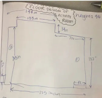
In addition, our team visited Achievement House and took measurements of the exercise room and of some clients who will be using the equipment. These can be seen below in Table 2.2, Table 2.3, and Figure 2.1. Danielle was not measured for the total wingspan or total standing height with arms raised because her mobility is not reflective of the athletes.
Table 2.2. Equipment Measurements
Equipment Measurement
Wheelchair 32”x26”x36”
Standard Chair 25”x25”x40”
Walker 25”x16”x38”
Resistance band (with handles) Length: 63”
Table 2.3. Client Measurements
Measurement Description
Client John (LxWxH) *In Standard Chair
Danielle (LxWxH) *In Wheelchair
Individual seated in chair 25”x25”x49” 32”x26”x50”
Wingspan 65” *N/A
Total seated height with arms raised 60” 66”
Total standing height with arms raised 75” *N/A
Distance from rack of chair to fingertips with arms straight out
40” 32”
Vertical height from floor to arms with arms straight out
42” 36”
Distance From Back of Chair to Feet with Legs Straight Out
48” 56”
*Measurements not recorded because they were less than John’s measurements.
Figure 2.1. Achievement House Exercise Room Layout
2.2 Product Research
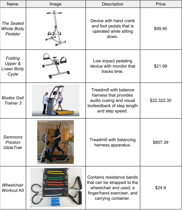
Table 2.4. Existing Product Descriptions and Images
Name Image Description Price
The Seated Whole Body
Pedaler
Device with hand crank and foot pedals that is
operated while sitting down. $99.95 Folding Upper & Lower Body Cycle
Low impact pedaling device with monitor that
tracks time.
$21.99
Biodex Gait Trainer 3
Treadmill with balance harness that provides audio cueing and visual biofeedback of step length
and step speed.
$22,322.30
Sammons Preston GlideTrak
Treadmill with balancing
harness apparatus. $807.39
Wheelchair Workout Kit
Contains resistance bands that can be strapped to the wheelchair and used, a finger/hand exerciser, and
carrying container.
$24.9
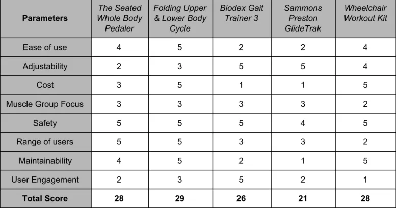
In Table 2.5, we developed a scoring system capable of ranking these products based on how they relate to our project. Of the products that are currently on the market, the Folding Upper & Lower Body Cycle achieved the highest score with 29 points. This product is highly
device serves as a safety harness for a specific type of treadmill and cannot be used by Achievement House because none of the staff is certified to remove someone from their wheelchair. After identifying the top products related to our customer needs, each product was ranked on a scale from 1 to 5, with a score of 5 being the best score, in terms of a range of parameters that were selected based on our customers primary needs. These scores were then added up in Table 2.5. A higher score corresponds to a product that is more likely to be helpful to us when drawing inspiration from current solutions.
Table 2.5. Benchmarking of Existing Products Based off of Customer Needs
Parameters
The Seated Whole Body
Pedaler
Folding Upper & Lower Body
Cycle Biodex Gait Trainer 3 Sammons Preston GlideTrak Wheelchair Workout Kit
Ease of use 4 5 2 2 4
Adjustability 2 3 5 5 4
Cost 3 5 1 1 5
Muscle Group Focus 3 3 3 3 2
Safety 5 5 5 4 5
Range of users 5 5 3 3 2
Maintainability 4 5 2 1 5
User Engagement 2 3 5 2 1
Total Score 28 29 26 21 28
2.3 Technical Research
A patent search was conducted in order to explore similar solutions that have already been invented. We identified several patents that were designed to be accessible for those with physical disabilities, primarily those in wheelchairs. Each patent has aspects that adhere to the different needs stated by our sponsor and athletes. Examples of ideas that could be utilized in our own designs include locking mechanisms to keep the wheelchair in place, propulsion aids that exercise different muscle groups, guided rail systems, etc. Each patent presents a unique solution to our problem. They can be seen in Appendix A: Technical Research.
In addition to our patent research, a search on related research journals was conducted. The following articles contained information beneficial to our own design:
This article speaks on the trend of low activity levels in children with physical disabilities and how engaging exercises help promote healthy lifestyles for them. This goes hand in hand with our objective to develop engaging equipment that encourages the user to want to exercise.
(2) "Enabling participation for disabled young people: study protocol." BMC Public Health.
This article discusses the participation levels of people with disabilities in activities, sports, and educational or business events. Considering we want to encourage activity and exercise levels for our customers, we utilized this article to develop an engaging method of exercise as part of our preliminary design.
(3) "Cardiorespiratory Fitness in Individuals with Intellectual Disabilities—A Review." Research in Developmental Disabilities.
This research report was conducted in order to identify how cardiorespiratory fitness levels differ between people with disabilities and those without them. “Low cardiorespiratory fitness levels have been found in individuals with intellectual disabilities (ID), which puts them at higher risk for cardiovascular diseases and all-cause mortality (3).” Since people with disabilities are likely to have lower fitness levels than those without, it is important that we consider their level of fitness when designing our equipment. In order to optimize the exercise equipment to
Achievement House’s needs, our design must be adaptable to users of various fitness levels.
(4) "Development of Physical Fitness in Children with Intellectual Disabilities." Journal of Intellectual Disability Research.
This journal contains a study that was conducted on children with intellectual disabilities and compares their physical fitness development to that of children without disabilities. The present study showed lower aerobic and muscular fitness in children with ID compared with typically developing children between 8 and 12 years (4). From this study, we realized that there are a wide range of physical and mental conditions that our design parameters must consider.
(5) "Adaptive Control of an Exercise Machine." Proceedings of the 15th Annual International Conference of the IEEE Engineering in Medicine and Biology Society.
This article discusses the use of an adaptive controller to limit the user to using the equipment in the most efficient way. This is related to our goal of using guides to limit the user’s motions, ensuring they are using the equipment correctly.
Past senior projects were also studied so that we could see how other groups solved problems similar to ours. The information we used to design our prototypes was taken from the following senior projects:
(6) “Universal Weight Machine” was a project completed by Cal Poly students in 2016 that involved creating a universally accessible multi- station exercise machine for the physical and mental well-being of athletes of the Special Olympics and Pathpoint Life Education &
Weight Machine” also included a low resistance pedaling station, which further supported our product research that showed the pedaling mechanism as the best option for exercise. An image of this project can be seen in Appendix A in Figure A.1.
(7) “Universal Play Frame VI” was a project designed by Cal Poly students in 2010 that consisted of an adaptive frame which supports a variety of devices that allows athletes in wheelchairs with limited range of motion to participate in physical activity. Dr. Kevin Taylor was the sponsor of this project, and we met with him in order to gain feedback on our ideas, as well as insight on what design parameters we should be considering for our project. From Dr.
Taylor’s advice, we realized that we needed to get to know our target consumers more, and also needed to design our project to match their abilities rather than just the average person’s
abilities. Figure A.2 in Appendix A displays an image of this project.
3.0 Objectives
This section of the Final Design Review documents the design considerations used to create the concept design. The design considerations were developed from the previously documented chapter on background research, and further developed by creating a problem statement, boundary diagram, and engineering specifications list.
3.1 Problem Statement
The overall objective of the project is to design and manufacture adaptive exercise equipment for people with varying levels of mental and physical disabilities. Non-adapted exercise
equipment does not have the safety features, support, or wheelchair features necessary to allow a wide range of people to participate. In addition, adaptive exercise equipment on the market today is expensive, which makes it challenging for non-profit organizations such as
3.2 Boundary Diagram
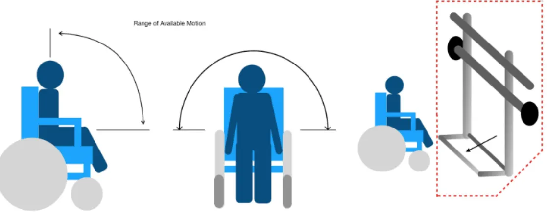
The purpose of a boundary diagram is to identify which aspects of the problem statement can and can not be adjusted using engineering methods. As mentioned, the device must be adaptable for people with varying levels of mental and physical disabilities. People who use a wheelchair have a narrower range of motion, as displayed in the first picture in Figure 3.1. This will have a large impact on the design of our product, because it limits what exercise
movements are possible. In the second picture, the arrow highlights a critical structural component that will greatly impact how clients in wheelchairs may approach the product.
Spacial awareness will guide the overall structural design of the device because of its impact on user ergonomics. After meeting our clients, it was determined that the device would not need to incorporate a wheelchair locking mechanism and that the wheelchairs would not be altered.
Figure 3.1. Boundary Diagram of Limitations of Wheelchair Users
Based on the desires of Achievement House and background research, our team used Quality Function Deployment (QFD) to create a “House of Quality”, included in Appendix B. QFD spurs product development by identifying the appropriate specifications for a design. The “House of Quality” weighs the different aspects of a design, how they meet the customer’s needs and wants, and how they compare to competing products. The specifications are listed from 1-5, (i.e. 1 - not important, 5 - extremely important). From the QFD, we developed the Engineering
Table 3.1. Engineering Specifications Spec.
#
Spec. Description Requirement or Target Tolerance Risk Compliance
1 Weight of Apparatus 200 lb +25 H I
2 Size Fits through door n/a M A,I,T
3 Ease of Use Pass/Fail n/a M A,I,T,S
4 Comfort Survey n/a M A,T
5 Customizability >3 muscle groups n/a M A,T 6 Low Mechanical
Complexity
Pass/Fail n/a H A,I,T
7 Durability Life of five years +/- 2 years
M A,T,S
8 Cost $400 +/- $100 H A
The specifications table lists the specification description, target value, tolerance, risk level, and compliance. The risk levels are (H) High, (M) Medium, and (L) Low. The compliance categories are (A) Analysis, (T) Test, (S) Similarity to Existing Design, and (I) Inspection. The compliance category indicates how each specification will be measured. The tolerance column indicates the range of acceptable values for each specification. For example, our target weight for the
apparatus is 200lb, but if the device is 225 lbs, it will still pass our design requirements. In addition, our requirement for size is that the device can fit into the room. This criteria is pass or fail, thus indicated by “n/a”. The risk column indicates how critical the specification is in terms of designing a functional product. The higher this column is rated, the more of a risk it will be to the user or sponsor if we do not achieve it with our design. Specifications marked with (H) are high risk, and will have a large impact on the success of the design. For example, the cost of the design is high risk, because without adequate funding, the project can not be manufactured. Therefore, this is a critical specification that we must consider. This exercise helped identify the most critical aspects of the design that may cause challenges in the future. Each specification is outlined below in further detail.
- Weight of Apparatus: The product must not require a machine to be transported around the facility. This will be measured based on how many people are required to move the product
- Size (height, width, length): The product must fit through a standard door. If not, if must be easily disassembled and reassembled.
- Ease of Use: The product can be set up for the user with two people. This will be measured based on how many people are required to set up the product
- Workout Customizability: The product can be used to target different muscle groups. This will be measured based on how many muscle groups the product can target. - Mechanical Complexity: The product is easy to operate mechanically. This will be
measured based on usage surveys by clients and instructors at Achievement House. - Durability: Our goal is to have the product require maintenance once per year. This will
be measured based off of a cycle test.
4.0 Concept Design
Our final concept design is the result of extensive brainstorming, prototyping, sponsor meetings, and ideation. We generated a method of weighing our top design models against the most important features of the exercise equipment, and used this model to generate a final design proposal.
4.1 Brainstorming
In the early stages of our idea development, our goal was to generate as many ideas as possible. This process was approached with creativity and openness, to allow for a wide range of unique ideas. A complete list of the generated ideas can be seen in Appendix C.
In addition, our team visited the Cal Poly Recreation Center to analyze exercise equipment and discuss its accessibility. This was followed by an ideation session where the goal was to figure out how we could make each machine more accessible to wheelchair users. After we had generated a substantial number of ideas, we had an additional meeting with our sponsor to review our concept models. Communication with our sponsor turned out to be a critical factor in the development of our final concept design. While we were focusing on creating equipment that would be fun and engaging, it was deemed that the most important function of our design was a product that can be used by all athletes and can target a wide range of muscles. From this meeting, we were able to narrow down the large list of ideas to a select few that we would develop concept models for.
4.2 Concept Modeling
Figure 4.1. Concept Upper Body Elliptical
The upper body elliptical functions similarly to a typical elliptical machine, but it is designed for a wheelchair user to achieve cardio exercise with their upper body. It would have adjustable resistance so the user can control the difficulty of their exercise, and is designed to fit a wheelchair. The user would lift the two parallel arms to exercise their upper body.
Figure 4.2. Concept Adaptable Rowing Machine
Figure 4.3. Concept Hand Pedaler
The hand pedaler works similarly to a stationary bike, but a wheelchair user is capable of rolling up to the machine and achieving a cardio workout using their arms. The resistance would be adjustable to allow the user to control the difficulty of the exercise. The stationary hand pedal could also be adjusted vertically for different heights.
Figure 4.4. Concept Rope Pull Machine
Figure 4.5. Resistance Band Pulling Device
This machine is used by pulling the resistance band attached, which causes the bar to move along the cutout path. The bar can also be anchored in a fixed position to perform stationary exercise. This would be a workout of the major muscle groups in the back and the arms.
4.3 Decision Matrices
In order to narrow down our ideas to a final design, we utilized a number of decision matrix methods recommended by our advisor. The first of these was developing Pugh Matrices for each of the functions our solution must perform. The Pugh Matrix allowed us to come up with the best designs for individual functions of the final design. We then used a System
Morphological Table to combine the best aspects from the Pugh Matrices into a few potential final designs. We then analyzed these designs in a weighted matrix, which allowed us to create a scoring system to see which design most effectively met all of the criteria. The highest scoring design can be seen in Section 4.4. These matrices can be seen in Appendix D at the end of this report.
4.4 Final Concept Design
Our final design came as a result of the decision matrices and another conversation with our sponsor. It is a combination of a resistance band rack, pedaler, and punching bag - providing the users with a full body workout station. Below is a preliminary CAD model of our final
Figure 4.6. Final Concept CAD Model
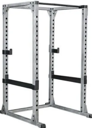
The resistance band rack was chosen because the trainer at Achievement House already incorporates resistance bands into the clients’ workouts. She currently is only able to attach the bands to the arm of a treadmill, so building an entire rack will allow her to add in more exercises and target more muscle groups. This type of exercise is also adaptable for a wide range of athletes, and has unlimited ways to adjust resistance.
The pedals located on the vertical plate on the right side of the CAD model were chosen
because the athletes and the trainer are interested in incorporating a method of cardio exercise for users in wheelchairs. In this design, the resistance of the pedaler is adjustable such that the difficulty of the workout may be controlled.
The punching bag will be mounted on a removable bracket that can be placed anywhere on the main frame of the apparatus. A punching bag was chosen because the athletes at Achievement House expressed interest in exercising by performing punching and kicking motions. The bag can be adjusted vertically to accommodate standing and seated users.
is a risk of corrosion when connecting aluminum and steel parts, we will need to coat the aluminum with a galvanizing compound spray that allows it to resist the corrosion.
4.5 Concept Prototypes
The next step was to develop more realistic physical prototypes. We used the concept
prototypes to help us get a better idea of how we could potentially manufacture certain aspects of the final design. Our primary focus was to brainstorm how the steel beams would fasten together, and how the pedaler would adjust along the resistance rack.
Figure 4.7. Resistance Band Rack Concept Prototype
Figure 4.8. Pedaler Adjustable Height Concept Prototype
This prototype is a potential solution to making the pedal height adjustable. The pedals would be attached to the fixture shown in Figure 4.8, and the pin that controls the height can be removed and placed into the other slots depending on how the user wants to use the pedals. The benefit of this design is that moving the pedalar between slots is easy and quick, which satisfies our goal of engineering a user friendly apparatus.
4.6 Potential Risks
The primary risks associated with our design come from incorrect use and structural stability. As with all exercise equipment, there is a risk of injury if the device is used incorrectly. While
performing customer research, we were informed that the athletes are supervised during every exercise class. Therefore, by educating the instructors of the risks and hazards of our device, we can better protect the athletes from injuring themselves. We predict that the most common mis-use of the device will be users hanging, swinging, or performing pull-ups on the rack and punching bag beam. To mitigate this risk, we will include diagrams on the final product that visually display what not to do on the rack. In addition, we may fix the structure to the wall of the exercise room as a safety precaution. While meeting with our sponsor, it was also decided that a plaque on the wall that displays visual images of different exercises would be useful. All
5.0 Final Design
This portion of the Final Design Review provides a detailed account of the final design, including parts, subassemblies, functionality, analysis, and cost.
5.1 Final Design Explanation
Our final design, displayed in Figure 5.1, features a main rack constructed from perforated galvanized steel beams that will be bolted together using external brackets, bolts, and lock nuts. It will be fixed to the wall of the client’s exercise room. The dimensions of the frame will be 90 inches x 52 inches x 52 inches, which will allow a wheelchair to roll into the center. Beams on all sides of the user allow for innovative resistance band placement; depending on the placement angle and relation to the body, a number of large muscle groups may be engaged. On the right side of the resistance rack, the pedaler is mounted to an adjustable vertical plate that is fixed to the rack using four bolts and nuts. The vertical plate can be moved up and down the rack by simply removing four bolts that fix it to the resistance rack. A pedaler mounted to a vertical plate allows users to “bike” with their arms, an adaptive and engaging form of cardiovascular
exercise. On the left side of the resistance rack, a punching bag on a removable bracket can be placed at any location on the rack, accommodating both seated and standing users.
5.2 Resistance Rack
The resistance rack shown in Figure 5.2.1 is made from perforated galvanized steel and is bolted together using 316 stainless steel external brackets. The brackets are held in place with ⅜’’-16 Grade 5 Steel Hex Bolts Grade 5, ⅜’’-16 Zinc-Plated Steel Nylon Insert Lock Nuts, and ⅜’’ Aluminum washers. See the Manufacturing Plan in Section 6 for a step-by-step guide on how to assemble the resistance rack apparatus. The total cost of the resistance rack assembly is approximately $620.00. The full cost breakdown can be seen in the iBOM in Appendix G.
Figure 5.2.1. Resistance Rack Assembly Drawing
Figure 5.2.2. External Brackets
Figure 5.2.3. Alternative Design Comparison
Figure 5.2.4 Resistance Rack Deflection and Buckling Analysis
Furthermore, there is an abundance of analysis that has been performed and made available to the public on UnistrutOhio.com by the manufacturer of the beams, Unistrut. For beam column loading, our biggest concern is with the longest beams so we will analyze the 90” beams on the resistance rack. The allowable loads for this length beam is around 2000 lbf, which is an order of magnitude larger than what we expect the rack to experience. For the bolts, manufacturer’s analysis was provided on Fastenal.com. We are looking at shear forces on the ⅜” and 7/16” grade 5 steel bolts. The loads can be upwards of 8000 lbf, which is orders of magnitude larger than we expect the bolts to experience on any component on our final design. These can be seen below in Table 5.2.1 and Table 5.2.2.
Table 5.2.2. Bolt Shear Load Analysis
The resistance rack will require minimum maintenance. Table 5.2.3 outlines the type of maintenance and corresponding frequency recommended by our team.
Table 5.2.3. Maintenance Recommendations
Type of Maintenance Frequency Tool Needed Provided Retightening bolts Every two months Wrench Yes
Cleaning beams Once a week Skin friendly cleaning and deodorizing spray
5.3 Punching Bag
The punching bag sub assembly includes a speed bag attached to a stainless steel bracket, which is then screwed into a perforated stainless steel bar. The assembly is attached to the resistance rack by bolting the two L brackets to the resistance rack. By allowing the punching bag to be moved vertically along the columns of the main frame, it can be utilized by both standing and seated users. The cantilever beam that extends away from the bracket gives enough clearance for the punching bag to swing in all directions and avoid hitting the main frame. It also allows for extra space between someone using the punching bag and someone inside the main frame. Figure 5.3.1 shows an assembly of the punching bag attachment. See the Manufacturing Plan in Section 6 for a step-by-step guide on how to assemble the punching bag apparatus. The total cost of the punching bag assembly is approximately $93.00. The full cost breakdown can be seen in the iBOM in Appendix G.
Figure 5.3.1 Assembly Model of Punching Bag Apparatus
Table 5.3.1 Cantilever Beam Loading for 18” Round Steel Tubing
5.4 Pedaler Mount
The pedaler mounting apparatus will consist of the pedaler fastened to a vertical plywood
platform The plywood will be bolted to two aluminum beams to provide support for the weight on the pedaler, and these beams will be connected to two steel columns on the main frame of the resistance band rack using four bolts and lock nuts. The pedaler is primarily designed for use by those with wheelchairs who cannot achieve a cardiovascular workout using normal cycling equipment due to having limited use of their legs. The user will be able to roll up to the pedaler and adjust their desired horizontal distance. The vertical height of the pedaler can be adjusted by removing four bolts and nuts that fix the vertical plate to the resistance rack, allowing it to be used for both leg and arm exercise. Figure 5.4.1 displays an isometric drawing of the pedaler mount, while Figure 5.4.2 displays an exploded subassembly of the pedaler mount. The total cost of the pedaler assembly is approximately $45.00. The full cost breakdown can be seen in the iBOM in Appendix G.
Figure 5.4.2 Exploded Subassembly of the Pedaler Mount
A structural prototype of the pedaler mount was built in order to test the strength of the brackets and if the bolts would be strong enough to support the shear stresses generated from the weight of the pedaler. From conducting tests on this prototype, we concluded that the strength of the screws supporting the galvanized tube straps was enough to keep the pedaler from shaking while being used. It was also concluded that the bolts were strong enough to support the load of a user exerting force upon the pedaler, which is also backed up by the bolt analysis that was conducted for the resistance rack in Table 5.2.2.
5.5 Cost Analysis and Funding
The total cost for our project is approximately $771.00. See Appendix G for the indented Bill of Materials (iBOM) detailing the full pricing estimate of our project.
Initially, we applied for grants from the Mechanical Engineering Student Fee Allocation Committee (MESFAC), as well as grants from CP Connect and Justin Wineries. From these grants, we received a total of $500 from MESFAC. We also reached out to local material suppliers for donations. We received donations from Traffic Management Inc., the suppliers of the beams, as well as Home Depot and Lowes, who supplied hardware and bracketry.
6.0 Manufacturing Plan
The following section describes the manufacturing plan for the verification prototype. In this section, the following aspects of the design will be addressed: material procurement, manufacturing steps, assembly and assembly steps.
6.1 Manufacturing Plan: Resistance Band Rack
6.1.1. Materials Procurement:
Table 6.1.1 below details the description, quantity, and supplier for the necessary materials to build the Resistance Band Rack. Refer to the Drawing Package in Appendix J for part details.
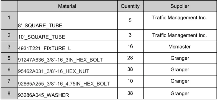
Table 6.1.1. Materials Required for Manufacturing of Resistance Band Rack
Material Quantity Supplier
1
8'_SQUARE_TUBE 5
Traffic Management Inc.
2 10'_SQUARE_TUBE 3 Traffic Management Inc.
3 4931T221_FIXTURE_L 16 Mcmaster
5 91247A636_3/8”-16_3IN_HEX_BOLT 28 Granger
6 95462A031_3/8”-16_HEX_NUT 38 Granger
7 92865A255_3/8”-16_4.75IN_HEX_BOLT 10 Granger
6.1.2. Machining Process:
*Navigate to Appendix K for instructions on how to machine the perforated square tubing to length. The beams will henceforth be referred to as Beam A, Beam B, and Beam C as specified in Step 7 of Appendix K.
The L brackets will need to have 4, 7/16” holes drilled in them as shown in Figure 6.1.0 below. Refer to the drawing package in Appendix J for the locations of the drilled holes. It is
recommended that the machinist align the L bracket on the desired joint and mark with a Sharpie marker where the holes need to be drilled to ensure that there is no misalignment.
Figure 6.1.1. Holes drilled in L bracket
6.1.3. Assembly Process:
1. Assemble the structure shown in Figure 6.1.1 below by connecting two Beam A posts together with two Beam C posts. Refer to the Drawing Package for a detailed exploded view that shows how each joint should be assembled and what specific bolts to use. Refer to Joint A in Figure 6.1.2.
2. The top and bottom Beam C posts shall be connected to the Beam A posts using L-brackets as specified in Figure 6.1.2 below.
3. The L-bracketry will be fastened using the bolts, washer, and nut. The head of the bolt should be secured against the holes on the L-brackets. The backside of the bolt should be secured with a washer followed by a hex nut.
4. Create two frames that resemble the image in Figure 6.1.1. Flip the direction of the screws into the bracketry.
Figure 6.1.3. Rack Assembly Joint A
5. Refer to Step Six Take one of the frames assembled from Steps 1-4, and insert one Beam D post as seen in Figure 6.1.3. It is essential to place the Beam D post exactly 18’’ away from the far right post. Secure the Beam D post in place by referring to Joint A in the drawing package and Figure 6.1.2.
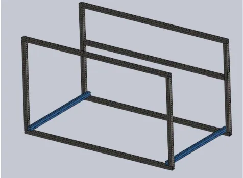
6. In this step the two frames will be fixed together with two Beam B posts. Referring to Figure 6.1.5, rest the two frames lengthwise on a flat surface, and insert the Beam B posts (highlighted in blue). Refer to Joint D in the drawing package and Figure 6.1.6.
Figure 6.1.5. Connecting Two Frames Together
7. In this step we will fix one more Beam B beam to the resistance rack. Flip the assembly over as shown in Figure 6.1.7. Refer to Joint D in the drawing package and Figure 6.1.6.
Figure 6.1.7. Assembly of Final Beam B Post to Frame
8. The last step of assembling the resistance rack is to fix two Beam B posts as shown in Figure 6.1.8. The assembler may decide how far apart the beams lay. Ensure that they are parallel to each other and perpendicular to the frame edges. Refer to Joint C in the drawing package and Figure 6.1.9.
Figure 6.1.9. Rack Assembly Joint C
9. Assemble the two structures from above together so that they form the full resistance band rack seen below in Figure 6.1.5. The same process explained in Step 6 is used.
6.2. Manufacturing Plan: Punching Bag
6.2.1. Materials Procurement:
Materials Procurement:
Table 6.2.1. Materials required for punching bag attachment
Material Quantity Seller
1 18" x 2” Galvanized Steel Square Tubing 1 SLO Traffic co. 2 4” Long, 2” Wide Inside Corner Brackets 2 Lowe’s
3 Zinc-Plated Bolt, ⅜” 16 Thread Size, 3” Long, Partially Threaded Grade 5
5 Home Depot
4 Steel Hex Nut Grade 5, Zinc-Plated, ⅜” 16 Thread Size
5 Home Depot
5 Swivel Mount 1 Amazon
6 Speed Bag 1 Amazon
7 2” x 2” Rubber End Cap 1 Amazon
6.2.2. Manufacturing Process:
Reference Figure 6.2.1 below:
1. Cut the steel tube to a length of 18” using a bandsaw.
2. Line up corner brackets such that the corner is flush with one end of the square steel tubing. Use a pencil to mark the locations of two points on the bracket that coincide with two holes on the tubing.
3. Use a drill press to drill ⅜” holes in the bracket. These holes should match up with holes in the tubing when the corner of the bracket is flush with the edge of the tube.
6.2.3. Assembly Process:
1. Bolt swivel mount to perforated steel tubing through the last hole on the tube. 2. Working on the opposite end of the steel tube from the swivel, bolt an inside corner
3. Repeat Step 2 of the Assembly Process, except this time, the bracket is bolted to the bottom face of the tubing.
4. Measure about 12” from the base of the front left leg of the main frame. 5. Line up the metal tube such that the top surface is 12” from the floor.
6. Attach the whole assembly by bolting the top and bottom inside corner L-brackets to the frame.
Figure 6.2.1. Model of Punching Bag and Rack Attachment Connectors.
6.3. Manufacturing Plan: Adaptive Pedaler Mount
6.3.1. Material Procurement:
Table 6.3.1 Materials Required for Adaptive Pedaler Mount Attachment
Material Quantity Supplier
1 1” by 7/16” Aluminum Square Tubing 48” 1 Home Depot 2 3/8-16 Zinc plated hex bolts 2.5" 4 Home Depot
3 3/8" Zinc Plated Washers 8 McMaster-Carr
4 3/8"-16 Zinc Plated Hex Bolt 3.5" 4 McMaster-Carr 5 3/8"-16 Zinc Plated Hex Nut 8 McMaster-Carr
6 0.75 inch Two-Hole U-bracket 8 Home Depot
7 #8-32 1/2“ Pan Head Screws 16 Home Depot
8 Plywood (24” x 24” x 0.5 “) 1 Home Depot
9 Pedaler 1 Facebook
6.3.2. Manufacturing Process:
1. Use a bandsaw to cut aluminum square tubing into two bars, each with a length of 22”. 2. Use a table saw to cut plywood to the dimensions displayed in Figure 6.3.1.
3. Drill 3/8-inch holes in the aluminum tubing and wooden platform at the locations
specified below in Figures 6.3.1 and Figure 6.3.2 using an endmill on the aluminum and a drill press on the wood.
Figure 6.3.2. Hole Locations in Wooden Platform (Side View)
6.3.3. Assembly Process:
1. Connect the aluminum tubing to the top and bottom of the wood platform using two 2.5-inch hex bolts and washers. Fully secure the connection using a 3/8-inch hex nut on each bolt. The bolts should be secured at the two inner-most 3/8-inch holes for both the wooden platform and the aluminum tubing. Figure 6.3.4 shows how the tubing and platform should be bolted, and also which location they should be bolted together at.
Figure 6.3.4. Aluminum Tubing Bolted to Wooden Platform (Top View)
2. Fasten the pedaler to the wooden platform by using the 0.75 inch U-brackets and power drilling them to the platform using the #8-32 1/2“ Pan Head Screws. Figure 6.3.5 shows how the brackets should be secured to the platform, and Figure 6.3.1 shows that each bracket should be screwed in at the location of each of the 0.16” diameter holes.
Figure 6.3.5. Bracket the Pedaler to the Platform
Figure 6.3.6. Aluminum Tubing on Rack Frame
6.4 Outsourcing
The perforated galvanized steel beams have been cut to length by Traffic Management Inc., a local supplier in San Luis Obispo. As mentioned in the manufacturing plan for the resistance rack, these beams need to be re-cut to their redefined lengths. All other manufacturing processes will be completed using Cal Poly’s machine shops.
7.0 Design Verification Plan
7.1 Engineering Specifications Testing
We planned to conduct tests regarding the weight capacity of the beams on the main frame, how much force is required to topple the apparatus, the size of the final product, how much force is required to displace the punching bag bracket, and the life cycle of the pedaler. See Appendix H for the Design Verification and Testing Plan.
7.2 Testing Facility and Equipment Needs
We will utilize the testing labs on campus to collect numerical data to determine the life cycle of the pedaler apparatus. All other tests will not require a special testing facility. The load to be placed on the center of the horizontal beams will consist of weight plates hanging on a chain; these will be borrowed from the Athletic Department’s weight room.
To test the weight capacity of the main frame, we will hang 250 lbs on the critical points of the beams to ensure that the frame can take the weight. This will back up our engineering
8.0 Project Management
Since submitting the Critical Design Review document, we have progressed significantly through the manufacturing and testing plans for our project.
However, due to the COVID-19 global pandemic, our spring quarter has been moved online. As a result, we are unable to physically manufacture and test our project. The project will be resumed by a team of students in the Fall of 2020, provided that it is safe for students to return to campus. Following are the processes we went through during Fall, Winter and Spring quarters of this senior project:
1.) Define: The first steps after receiving the project proposal were to conduct background research on related products, patents, and relevant information regarding our client. We visited our sponsors in Paso Robles, CA twice to speak with our main point of contact and to the athletes for whom we are designing this project for. To gain further insight into what is needed by our target community, we spoke with a Cal Poly professor with numerous years of experience designing equipment for people with disabilities. See Appendix B for the QFD, a chart to help us benchmark and prioritize our design process.
2.) Create: During the ideation phase, we used several methods to brainstorm ideas and came up with a multitude of individual concepts. Some of these ideas were amalgamated to form a few broad, overall designs. A combination of background research coupled with engineering intuition helped us create several solutions to our problem definition.
3.) Evaluate: Evaluation of our designs began with decision matrices (Appendix D) to clarify which ideas would best meet our design specifications. The decision matrices were important because they analytically and numerically categorized the designs without emotional input. Next, concept prototypes were constructed to further evaluate the feasibility of our ideas. This stage was particularly insightful as it revealed how a design might function in three dimensions. Using the preeminent concepts pushed forward by the decision matrices and the functionality and feasibility of our prototypes, a CAD model was created to show a realistic version of our chosen design. See Figure 4.6 for the concept CAD model. As of November 12, 2019, the evaluation phase of the design process is complete.
4.) Specify: Further design analysis and CAD was conducted to refine our ideas. A Failure Mode and Effects Analysis (FMEA) was completed to review the design and prompt ideas on how it might be improved. This is done by analyzing the ways in which the design might fail to perform its functions and how those failures might affect the
users. This includes exploring potential safety risks and how those risks will be mitigated.
analysis determined what materials needed to be purchased for the construction of a Structural Prototype. Our Structural Prototype is the final version of the pedaler attachment to the main frame. It provides further insight into the feasibility and critical functionality of the design with room for subsequent improvements.
Additionally, a detailed CAD model was created to specify dimensions and part
assembly. From the CAD models, a Manufacturing Plan was produced to detail how we will build the verification prototype. This includes how and where wel purchased
materials and components, a step-by-step manufacturing sequence, an assembly plan, and any outsourcing that may be required. Cal Poly shop technicians have reviewed and approved our Manufacturing Plan. See Chapter 6 for the full Manufacturing Plan.
A Design Verification Plan was created in which we assessed how our verification prototype meets all determined specifications. It includes plans to test our design and any facilities or equipment needed to do so.
5.) Build: Prior to the COVID-19 pandemic, we had purchased most of our materials. Unfortunately, we were unable to construct our final project due to our campus closing and school being moved online.
6.) Test: After assembling the final project, we would have conducted a
hardware/safety demo and a test of the completed system. The project would have concluded in a final design review and the senior design project exposition where we would share our project with the public.
Due to COVID-19, we were unable to build our project and thus were unable to test it. Instead we revised our manufacturing plan for future students to take on the project. Instead of an in-person exposition in which all senior project teams would share their work, we have created a webpage detailing our final project. See Cal Poly SLO’s senior project database to view this webpage.
Table 8.1 Timeline and Description of Major Deliverables
Major Deliverable Description Deadline
Preliminary Design Review (PDR)
First review of all preliminary solutions and problem statement. Deliverables are a presentation, report, and prototype. PDR will be presented to the sponsor.
11/12/2019
Failure Mode and Effects Analysis (FMEA)
Analysis of potential ways the design may fail and potential effects failures
may have on users. 11/19/2019
Detailed CAD Model
CAD model of the verification
prototype with specific dimensions and
components 01/14/2019
Manufacturing Plan Step-by-step process on how the third prototype will be manufactured. 01/28/2019
Design Verification Plan
Assessment of how the verification prototype meets design specifications and any changes to further improve the product.
01/28/2019
Critical Design Review (CDR)
Contains all the information needed to build design, including the
manufacturing plan and design verification plan. Deliverables are a presentation, report, and prototype. CDR will be presented to the sponsor.
02/04/2020
Final Design Review (FDR)
Final project review. Includes any updates/changes made during the build stage. Deliverables are an updated manufacturing plan for future students to take on the project and a webpage detailing our work. FDR will be presented virtually to the sponsor.
9.0 Conclusions
References
Texts/Articles/Research Reports:
1. Thomas D O'Brien, Jane Noyes, Llinos Haf Spencer, Hans-Peter Kubis, Richard P Hastings and Rhiannon Whitaker, Systematic review of physical activity and exercise interventions to improve health, fitness and well-being of children and young people who use wheelchairs, BMJ Open Sport & Exercise Medicine, 2016.
2. Carroll, Penelope, et al. "Enabling participation for disabled young people: study protocol." BMC Public Health, vol. 18, no. 1, 2018.
3. Oppewal, Alyt, Thessa I.M Hilgenkamp, Ruud Van Wijck, and Heleen M Evenhuis. "Cardiorespiratory Fitness in Individuals with Intellectual Disabilities—A Review." Research in Developmental Disabilities 34.10, 2013.
4. Hartman, E., J. Smith, M. Westendorp, and C. Visscher. "Development of Physical Fitness in Children with Intellectual Disabilities." Journal of Intellectual Disability Research 59.5 (2015): 439-49.
5. Li, P.Y, J. Shields, and R. Horowitz. "Adaptive Control of an Exercise Machine." Proceedings of the 15th Annual International Conference of the IEEE Engineering in Medicine and Biology Society (1993).
Past Senior Projects:
1. Oscar Andrade, Bibiana Koch, Robert Molloy, Haley Renfro, Emily Woods. “Universal Weight Machine.” Mechanical Engineering, June 2016.
2. Justin Bazant, Cullen Crackel, Anthony Franceschi. “Universal Play Frame VI.” Mechanical Engineering, December 2010.
Product Research:
1. The Seated Whole Body Pedaler
https://www.ha...aAsxDEALw_wcB
2. Folding Upper & Lower Body Cycle
https://www.wa...aAvc1EALw_wcB
3. Biodex Gait Trainer 3
https://www.4m...aArz4EALw_wcB
4. Sammons Preston GlideTrak
https://www.4m...lidetrak.html
5. Wheelchair Workout Kit
Appendices
Appendix A - Technical Research
Name Number Description
Exercise apparatus for wheelchair bound
persons
US5536228A
A simple, inexpensive exercise apparatus for wheelchair bound persons which allows them to exercise all upper body muscle groups while remaining in their wheelchair. A horizontal platform receives the wheelchair in a forward or rearward orientation, depending on which
exercises are to be performed. The wheels of the chair are then locked, and an elastic rope with handles at each end is positioned behind one of several matched pairs of rope guides, situated on a mast, an overhead unit, or on the platform, again depending on the desired exercise.
Combination arm exercise apparatus and
propulsion aid for a wheelchair
US6048292A
The invention is a combination arm exercise apparatus and propulsion aid for a wheelchair. Typically, a wheelchair user pushes a wheelchair using the triceps, pectorals, and deltoids,
exercising these muscle groups extensively without exercising the opposing muscle groups: biceps, trapezius, and latissimus dorsi. The invention exercises the biceps, trapezius, and latissimus dorsi when stretched, and assists the triceps, pectorals, and deltoids in pushing the wheelchair forward as it retracts.
Wheelchair accessible weight training
apparatus
US5044629A
Wheelchair aerobic
exercise trainer US5704876A
Invention includes a platform that is adapted to receive a wheelchair. A support mechanism is coupled to the platform and supports the majority of the weight of the wheelchair and a wheelchair occupant when the wheelchair is placed onto the platform. The wheelchair trainer includes a load mechanism that engages the wheels of the wheelchair and adds a variable resistance to rotation of the wheels thereby allowing the wheelchair occupant to achieve an aerobic workout.
Adapted fitness
equipment US20190254913A1
An exercise apparatus includes an adjustable frame being attachable to an assistive
ambulation device. The adjustable frame
includes removable handles, fitting arms located on a lower portion of the adjustable frame to receive a fitness attachment, and attachment points on located on the lower portion of the adjustable frame to couple a resistance device. The flexible tubing includes a soft sphere shaped object fastener to connect the soft sphere
Prior Senior Projects:
Figure A.1. Universal weight machine senior project
Appendix C - Idea List
Top Ideas
Resistance Band Structure Row Machine with Wheelchair Locks
Weight Lifting Apparatus for Upperbody Resistance Band Wall Rack
Additional Ideas Generated - Bungee cords
- Full body exercise - Whack a mole
- Track with weights that roll - Hammer
- Cycle - Monkey bars
Appendix D - Decision Matrix
Needs/Wants Size Portable Adaptable Low Cost
Manufacturing Simplicity
Workout
Capability Total
Weight 3 1 5 4 2 5
Bolted frame w/ hooks for resistance bands
1 1 5 4 5 3 68
Bolted machine w/ weight plates and
changeable grips
4 2 4 1 1 2 50
Adjustable foot and hand pedaler
5 5 1 4 3 1 52
Resistance band chamber w/ adjustable
bike pedaler and punching bag
Appendix E - Gantt Charts
Figure E.1 Gantt chart through SOW milestone
Figure E.3 Gantt Chart through CDR milestone
Figure E.4 Gantt chart through manufacturing and test review
Appendix H - Design Verification/Testing Plan
Test Procedure
Team Steam
Test #1:
Tipping/translation with applied force
Description:
The force required to make the equipment tip or slide will be tested. The magnitude of
the force will be increased steadily and the angle the force is applied at will be varied.
The test will determine whether we will secure the equipment to the wall or floor.
Location:
Cal Poly campus - Mustang 60
Required PPE:
● Closed toed shoes
● Long pants
● Safety Glasses
Required Materials:
● Force Gauge
● Protractor
● Eye bolt
Testing Protocol:
1. Assemble equipment entirely
2. Secure the eye bolt to the top, frontmost beam of the resistance rack
3. Connect the force gauge to “eye” of the eye bolt
5. Starting at 0 lbf, increase the tensile force applied by 10 lbf increments until the
rack either translates or begins to tip
6. Record the results below
7. Decrease the angle of the force gauge by 15 degrees (should be angled
downwards)
8. Repeat steps 5 and 6.
9. Continue this process until the angle of the force gauge is at 90 degrees
(perpendicular to the floor)
10. Increase the magnitude of the force in 10 lbf increments until the rack begins to
tip
11.Record final results below
Results:
Angle (degrees) Type of motion to occur first
(tipping/translation)
Force at which motion occurred
0
15
30
45
60
75
90
Test Procedure
Team Steam
Test #2:
Connection strength between rack and pedaler mount.
Description:
The load required to make the equipment tip or lose stability will be tested. The
magnitude of the force will be increased steadily, and the deflection of the mounting
platform due to stress will be measured. The test will determine the maximum load that
the mount can sustain, as well as the required torque that must be applied to the bolts in
order to sustain this load.
Location:
Cal Poly campus - Mustang 60
Required PPE:
● Closed toed shoes
● Long pants
● Safety Glasses
Required Materials:
● Force Gauge
● Ruler
● Torque Wrench
Testing Protocol:
1. Assemble equipment entirely.
2. Secure the mount to the resistance rack.
3. Connect the force gauge at the center of mass of the pedaler.
4. Obtain the initial position of both of the mount’s beams with no load applied.
5. Starting at 0 lbf, increment the applied force by 5 lbf until either beam has
deflected 0.1 inches. Record results of each test below.
Results:
Applied Load (lbf)
Top Beam Position (in)
Bottom Beam Position (in)
0 lbf
0 in
0 in
What factor of safety is obtained from the maximum load and does it meet design
criteria?
Test Procedure
Team Steam
Test #3:
Beam deflection
Description:
Though the main frame is not meant to be swung on, a beam deflection test will be
conducted to ensure that the structure will not fail if someone were to hang on it.
Weights will be hung from the center of a top beam and the deflection of the beam will
be measured.
Location:
Cal Poly Mustang 60
Required PPE:
● Safety glasses
● Closed toed shoes
● Long pants
Required Materials:
● Mass scale
● Ruler
● Weight plate
● Chain
Testing Protocol:
1. Assemble full frame
2. Weigh the chain and weight plate
3. Hang weight plate from upper beam using the chain
4. Use ruler to measure beam deflection
Results:
Applied Load (lbf)
Deflection (in.)
Appendix I - Project Budget
Component Part
Identifier Supplier Location Quantity
8' Square Tube n/a
TMI 795 Buckley Rd Ste. 3, San Luis Obispo, CA 93401
8
10' Square Tube n/a 3
L-Bracket 4931T221 McMaster https://www.mcmaster.com/4931t2
21 16
T-Bracket 4931T219 McMaster https://www.mcmaster.com/4931t2
19 4
3/8-16 3'' Hex Bolt 91247A636 McMaster https://www.mcmaster.com/91247a
636 32
3/8-16 Hex Nut 95462A031 McMaster https://www.mcmaster.com/95462a
031 46
3/8-16 4.75'' Hex Bolt 92865A255 McMaster https://www.mcmaster.com/92865a
255 14
3/8 Aluminum Washer 93286A045 McMaster https://www.mcmaster.com/93286a
045 46
Punching Bag n/a Target
https://www.target.com/p/everlast-p latform-speed-bag-6-pc-set-black-r ed/-/A-10244188
1
1/4'' Steel Plate 204325592 Home
Depot
https://www.homedepot.com/p/Ever bilt-1-4-in-x-4-in-x-12-in-Plain-Steel -Plate-800497/204325592
2
3/8” Steel Round Bar 204273959 Home Depot
https://www.homedepot.com/p/3-8-i n-x-36-in-Plain-Steel-Round-Rod-8 02447/204273959
1
36" x 3/4" x 1/16" Plain Steel
Round Tube 204225742
Home Depot https://www.homedepot.com/p/Ever bilt-36-in-x-3-4-in-x-1-16-in-Plain-St eel-Round-Tube-801237/20422574 2 1
0.5'' x 18'' x 20'' Wood Platform 202093832 Home Depot https://www.homedepot.com/p/San ded-Plywood-Common-15-32-in-x-2-ft-x-2-ft-Actual-0-451-in-x-23-75-i n-x-23-75-in-300888/202093832 1
0.75'' Galvanized Tube Strap 303434704
https://www.homedepot.com/p/Oat ey-3-4-in-Galvanized-Tube-Strap-2 -Hole-10-Pack-33543/303434704
Pedaler n/a Facebook n/a 1
#8 x 1/2 in. Pan Head Zinc Plated
Screw 204275069
Home Depot
https://www.homedepot.com/p/Ever bilt-8-x-1-2-in-Phillips-Pan-Head-Zi nc-Plated-Sheet-Metal-Screw-100-Pack-801582/204275069
16
1" x 48" x .0625" Square
Aluminum Tube 204273940
Home Depot
https://www.homedepot.com/p/Ever bilt-1-in-x-48-in-Aluminum-Square-Tube-with-1-16-in-Thick-801307/20 4273940
1
Appendix J - Drawing Package
Resistance Band Rack
Punching Bag
Pedaler Mount
Appendix L - Operation Manual
Operation Manual: Resistance Rack
Material Procurement:
Table 1.1 Materials Required for Resistance Rack
Material Quantity Supplier
1
8'_SQUARE_TUBE 5
Traffic Management Inc.
2 10'_SQUARE_TUBE 3 Traffic Management Inc.
3 4931T221_FIXTURE_L 16 Mcmaster
5 91247A636_3/8”-16_3IN_HEX_BOLT 28 Granger
6 95462A031_3/8”-16_HEX_NUT 38 Granger
7 92865A255_3/8”-16_4.75IN_HEX_BOLT 10 Granger
8 93286A045_WASHER 38 Granger