Exploiting the Forecast Channels for Power
Allocation in High-Speed Railway Communications
Chan Dai Truyen Thai*, Marion Berbineau* and Fan Sun
†
*Univ Lille Nord de France, F-59000, Lille, IFSTTAR, LEOST, F-59650, Villeneuve d’Ascq
†
Department of Electronic Systems, Aalborg University
Email:
{
chan.thai, [email protected]
}
, [email protected]
Abstract—A High-Speed Railway (HSR) communication sys-tem also has its own advantages compared to a conventional cellular system due to the fixed railway infrastructure and a priori known position of the trains. Based on the measurement results and analysis regarding the propagation channels for HSR communications in literature, this paper distinguishes and analyses the permanent and temporary elements affecting the channels. The characteristics of the channel at the positions when the train will pass in a short time (called here “future” channel) can be forecast based on the permanent elements and therefore provide a novel method to minimize the total transmit power and range for transmitting uplink packets with a certain time-to-live (TTL) period. A power reduction up to 20 dB can be achieved for packets with TTL period of 200ms.
I. INTRODUCTION
A. Motivation
In recent years, High-Speed Railway (HSR), providing a fast and convenient travel, has been deployed rapidly around the world. Offering a reliable and high-performance communi-cation for the passengers draws a great attention of the railway operators. It is a challenge for the research community due to the following reasons [1]–[3]. First, the signal from the Base Station (BS) cannot well penetrate the windows of the train carriages made with special materials that can stop the radio waves. Second, the Doppler shift is high because of the high speed of the train. Third, a lot of mobile users handover in the same cell at the same time will arise difficulties to the network control particularly during handover process.
To tackle the problems, a two-hop network architecture has been proposed [4]. All mobile users in the train are connected to distributed in-train antennas which are inter-connected by Radio-over-Fiber (RoF) links and to a central Access Point (AP) [2], [5]. The AP connects to the BS by antennas mounted on the roof of the train. By doing so, the AP aggregates all connections of the mobile users into one connection with an extremely high rate to the BS.
This can be well facilitated by using all frequency bands and time slots instead of giving each of those to each user if all users directly connect to the BS. In addition, the antennas inter-connected and located all along the train length can act as an antenna array, instead of separated users, and level up the performance. Because the users move with the train at the same speed, the communication between them and the AP through the in-train antennas can be Wi-Fi-based
and is quite reliable. The remaining issue is the train-to-ground communication which suffers from a high Doppler shift and fast-changing channels. In this paper, we therefore only consider the train-to-ground communication link.
Because the train moves with a very high speed, about 250 km/h to 400 km/h, for the uplinks, the AP has to vary the transmit power with a very high pace and in a very large range. It can be several orders of magnitude within time frames of the order of a second [2]. Reducing the transmit power and range is therefore an important problem.
B. Exploiting the Information of the “Future” Channels
For a general cellular communication system, because the direction and speed of the movement of the users are not known a priori and considered to be random according to a cer-tain model, many techniques such as power control and power allocation, resource allocation, routing decision, etc. are based on the information of the current channels and sometimes of the past channels, e.g. for fairness among the users. Very little information of the channels in the future can be obtained. It is therefore not widely used for the techniques mentioned above. On the other hand, the communication system for HSR is considered as more disadvantageous compared to the cellular system as mentioned above. However, the advantage is that we can forecast the channels to a certain extent.
Exploiting the information of a channel in the future can help to optimize the power allocation in order to reduce the total transmit power and varying range. Actually, packets sent from a source to a destination always has a certain time-to-live (TTL) period which depends on the delay requirement of the service. Some packets can be therefore kept at the AP for a short period, without violating the delay requirement, to wait for good channels to come. Because the railway is permanent, the path loss of the channel is thus fixed for the whole routine and can be calculated a priori. In addition, with a high speed of the train, the magnitude of the channel changes very fast thus the packets do not need to wait for a long time to be sent to the BS over good channels.
We can divide the elements affecting the channels into two groups. The first group includes the elements which change really fast such as any kind of moving objects. We therefore cannot make any guess about the effects by the elements in this group. The second group includes the elements which do
not change in a certain period of time, let us say τ (s), such as the geographical environment (mountains, rivers, lakes, etc.). If τ is as long as several months, we can measure the characteristics of the channels affected by these permanent elements and use the corresponding information for all the train schedules in the same railway tracks for that time period of τ. Ifτ is only a few hours, we can use the information for one or two train schedules after the measurements were carried out in another train which passed after τs ago. A database for this permanent characteristics for the whole railway track is then stored and used in every train route in the sameτperiod. The duty here is of course to identify which characteristics of the channels are affected by the temporary group and which are not. Although there have been several publications recognizing some characteristics which depend only on the communication distance such as path loss, average K-factor of Ricean fading while other characteristics are random [1], [7], [8], to the best knowledge of the authors, there has not been any publication which clearly distinguishes the permanent and temporary characteristics in order to exploit the information about the future channels. Therefore in this paper, we use the path loss and average K-factor to forecast the channels as recognized so far. However, if more characteristics are identified, the optimization will be more precise and give a better performance. This paper proposes and analyses a novel scheme to optimally buffer the packets in the AP for minimized transmit power and range.
In a communication system, the advantage in terms of information can be “transferred” to gains in other aspects. In a wide sense, exploiting the information about the con-text/environment to enhance the performance of the commu-nication, can be called mobility-aware, traffic-aware, position aware etc., has been considered in a very wide area in which each topic considers a different aspect of the issue such as routing, energy consumption etc. For example, the information about the interference, which is sometimes considered as harmful, can actually boost the rates if a system is carefully designed [6]. In other aspects, the mobility can be used to optimize the retransmission limit [9] or resource provisioning strategy [10]. On a narrower focus, to our best knowledge, this paper first proposes a novel method to use the information of the channels of a railway communication for optimal power allocation.
The paper is organized as follows. Section II presents the channel and traffic model as well as different coverage layouts. Two types of power allocations are described in details in Section III. Section IV shows and discusses the numerical results and Section V concludes the paper.
II. SYSTEMMODEL
A. Channel Model
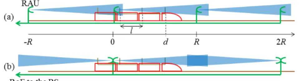
We consider a coverage type in which the remote antenna units (RAUs) are located R-m away from each other as seen in Fig. 1(a). Assume that the train has N coaches each with a length of l m and one antenna. The distance between the two nearest antennas is therefore also l m. All antennas are connected to a common processor by RoF links. The train
moves from left to right with a velocity ofvm/s. One antenna of the train can be served by several RAUs at the same time however we only consider M nearest RAUs. The channel between one antenna of the train and a RAU at a certain time is modeled as reciprocal and, with a real-time manner, known at both receiver and transmitter.
The channel measurements in [1], [7] shows that a channel is affected by a combination of path loss, Log-normal shad-owing and Ricean fading. The average K-factor of the Ricean fading for a low distance, which is considered in this paper, lin-early decreases with distance byK¯LOS=−0.0337d+ 23.05. We therefore consider that a channel coefficient is given by
h= q
K
dαgs, K = λ 4π
dαo−2, where α is the path loss ex-ponent,K is a constant depending on the used frequency and the reference distancedo;d is corresponding distance;g and
s are Ricean fading and Log-normal shadowing coefficients respectively. The instantaneous K-factor andlnsare normally distributed with variances σ2
K and σ 2
lns respectively. The K-factor is therefore the sum of the average component and an additive “noise” componentKLOS= ¯KLOS+ ˜KLOS.
The channel betweenNantennas of the train andM nearest RAUs isM×N matrixH={hi,j}wherehi,j is the channel between antennaiand itsj-th RAU. Note that due to the train length, each antenna has a different set of M nearest RAUs. The transmissions are conducted in the same frequency band and in a normalized bandwidth of 1Hz.
B. Coverage Layout Analysis
Fig. 1 shows two coverage layouts for a HSR network. In (a), each RAU is supported by one tower whereas in (b) twos RAUs are supported by one tower. However in (b), the vicinity of a RAU is not covered due to very low distance. This is avoided in (a) by increasing the coverage radius of a RAU a little bit. Below we consider the coverage type in (a) with
M = 2, the other can by analyzed in a similar way.
Consider an uplink from the train to the BS. The position of the train, defined as the position of the first antenna, isd1. If
0≤d1 < R, the two nearest covering RAUs to the antennas with positionsdi such that0≤di< Rare the RAUs at 0 and at−R while the two nearest covering RAUs to the antennas with positionsdisuch that−R≤di<0are the RAUs at−R and at−2R.
At time slot k, signal x[k] = (x1[k], x2[k], ..., xn[k]) is transmitted from the train throughNantennas, different RAUs receive the signals and forward them to the BS. The BS receives y[k] = H[k]x[k]. If the transmit power covariance matrix of the train isP[k], the maximal achievable rate of the transmission is
C(H[k],P[k]),log2det IM+H[k]P[k]H†[k] (1)
whereH† is the conjugate transpose ofH [11].
C. Traffic Model
Fig. 1. Two types of coverage. Here we use the first type to analyze.
period of T time slots. Here because the network core is not taken into account, the TTL field in the packet refers to the remaining time before it has to be delivered to the BS or in this context the maximum storage time of a packet in the AP. Assume that at time slotk, there areacoming packets. On the other hand, because using the normalized bandwith of 1Hz, we assume that each packet has only 1 bit.
III. POWERALLOCATION
We divide the time axis into periods each withKtime slots.
A. Without exploiting the information about the forecast chan-nels
In a conventional scheme, the information about the “future” channels is not exploited, the power control is based on the current knowledge of the channels. For a MIMO channel, the power levels allocated to the antennas are selected so as the current data rate demand is satisfied. They are optimized such that the total power is minimized for time slotk as follows
minimize Tr(P[k])
subject to C(H[k],P[k]) ≥ a. (2)
The average optimized transmit power is therefore 1
K
PK
k=1Tr(Po[k]).
B. Exploiting the information about the forecast channels
Because not only the railway routine is fixed and known a priori but also the speed of the train at a certain time is supervised and controlled at a certain precision, the positions of the train in the near future can be calculated. Hence we can forecast the path loss and average K-factor of the channels. In case the channel is very good, we transmit all buffered packets because it required less power. In case the channel is very bad, the packets are buffered until the channel becomes good. Because the train is long, there is a possibility that one of the antennas gets close to a certain RAU after a short interval, assuming that the RAUs are deployed close enough. This will be discussed in Section IV with numerical results. Consequently, the faster the train moves, the shorter the interval in which the packets have to “wait” for the good channel.
The path loss and average K-factor determine the average channels which will be known. The random shadowing and
the random additive component of K-factor K˜LOS make the channels fluctuate around the average values. The proposed scheme is therefore described in two phases. In phase 1, before a period of K time slots begins, we use the average values of the future channels, H0[k] = {h0
i,j}, from k = 1 to k =
K to optimize form an optimization problem. The channels
h0 =qdKαg
0s0 has an average shadowing s0 =
Es= 1. The Ricean fadingg0 has average K-factor ofK¯LOS. We then can calculate the transmit power and the corresponding rater[k]in each time slot. In phase 2, the period of K time slots starts. At each time slot, knowing the new information about the current channels, we will adjust the transmit power to achieve the pre-determined rate ofr[k]. If the channels get worse, we need to increase the pre-allocated Tr(P0o[k]) to a new value of Tr(Po[k]). The elements of the matrix are also changed accordingly to the change of the channels. If they get better, we need to decrease them accordingly to save the energy.
Because the rates are not changed, the deadlines for the packets are not violated.
1) Phase 1: To optimize for the forecast channels, we have the following problem.
minimize PK
k=1Tr(P0[k])
subject to PT+1
k=1C(H0[k],P0[k]) ≥ a
PT+2
k=1C(H0[k],P0[k]) ≥ 2a
...
PK−1
k=1 C(H0[k],P0[k]) ≥ (K−T)a
PK
k=1C(H
0[k],P0[k]) ≥ Ka
PK
k=2C(H
0[k],P0[k]) ≥ (K−1)a
PK
k=3C(H
0[k],P0[k]) ≥ (K−2)a
...
PK
k=K−1C(H
0[k],P0[k]) ≥ 2a.
(3) Because a packet has a T remaining time slots before delivered to the BS, the AP in the train can keep it up to T time slots to wait for a good channel in order to minimize the total power. The constraints in (3) are divided in three groups separated by two lines as shown.
time slot T + 2 finishes. Therefore the total rate in the first
T + 2 time slots must be enough to carry 2a bits for the packets coming the first two slots. The following constraints in the same group have the same reasons. To finish a cycle, when the last time slot finishes, all packets must be delivered to the BS. This is written in the only constraint in the second group.
On the other hand, a packet cannot be delivered to the BS before it comes to the AP. For example, the coming packets in time slot 2 cannot be delivered to the BS in time slot 1. This is expressed in the first constraint in the third group. The last
K−3 constraints are for the next time slots with the same reasons.
After the optimized transmit powersP0o[k] are determined, the corresponding rates are calculatedr[k] = C(H0[k],P0o[k]). 2) Phase 2: To optimize for the current real channels, we have the following problem.
minimize Tr(P[k])
subject to C(H[k],P[k]) ≥ r[k]. (4)
The average optimized transmit power is therefore 1
K
PK
k=1Tr(Po[k]).
IV. NUMERICALRESULTS
We use Matlab simulations to show some numerical results for a train with speed 360 km/h. All packets coming to the AP in the train with a constant rate of a = 3 bits/s and a TTL period of T = 200 ms. The rate here is considered a normalized rate because we use a bandwidth of 1 Hz to transmit to the BS. The variances of lns and K˜LOS are
σln2s = 1 andσ2K = 1 respectively. The time axis is divided into periods of 600 ms. In each period, the transmit powers in the reference scheme described in Section III-A and the proposed scheme are calculated and averaged based on several channel realizations.
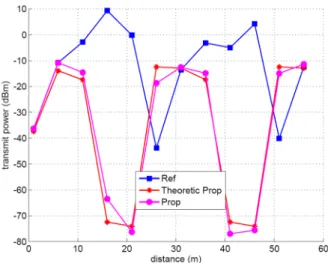
Fig. 2 shows the transmit power in dB of the reference scheme (Ref) and the proposed scheme (Prop) for a certain channel realization, not averaged over several realization. The
x axis is the position of the train when it moves from the beginning (at 0). The Theoretic Prop curve shows the transmit power after Phase 1 of the proposed scheme is finished. The Theoretic Prop curve (Phase 1) and the Prop (Phase 2) curves show different transmit powers. The former is lower or higher than the latter depending on how the channels change compared to the forecast channels. Let us call the distance of the antenna-RAU pair which has the shortest distance asdmin. The Prop curve shows the real transmit power for the proposed scheme. The transmit power in the reference scheme increases whendminincreases. At those times, in the proposed scheme, the packets are stored to avoid spend high power because it is not efficient to use bad channels. The transmit power level right after that, when the channels are good, soars to transmit stored packets since the TTL periods are limited.
Fig. 3 shows the accumulated data delivered by the schemes. The Required curve shows the accumulated data which must be delivered to satisfy the deadlines of the packets. It is at 0 for the first time slots since there is time for the first packet to be stored. After that, it increases with a constant rate until time
Fig. 2. Transmit power required with varied distance.
Fig. 3. Transmit required power with varied distance.
slotK−1. At the last time slot, all packets must be delivered regardless of the TTL period of the stored packets. The curves of the two schemes must be above the Required curve. The Ref curve increases with a constant rate of the arriving packets because it delivers the packets constantly in every time slot. The Theoretic Prop curve correspond to the proposed scheme after Phase 1 finishes. It can therefore violate the Required curve because it is calculated based on the forecast channels. The Prop curve must hence compensate this violation and make it satisfy the requirement. We can see that at points the Theoretic Prop curve decreases and violates the Required curve, the Prop curve is adjusted to be above the Required curve while at points the Theoretic Prop curve increases high, the Prop curve is adjusted to be equal to the Ref curve.
Fig. 4. Ratio of transmit power allocated to different antennas.
Fig. 5. Transmit power for the reference and proposed schemes.
will be negligible. These two antennas are therefore selected as transmit antennas. In addition, the random shadowing and instantaneous K-factor can make the channels for the two antennas very different, devoting all power to the best antenna is thus reasonable.
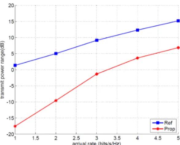
Fig. 5 compares the transmit power in dB for the reference and proposed schemes with respect to different constant arrival rates. As we can see the proposed scheme can save a lot of energy. Increasing the train’s speed and the TTL period for a certain RAU length can even increases the difference in power used by the two schemes because the channels change faster and there are more time to store the packets and the optimization therefore gives more benefits. The power ranges of the two schemes also have a similar comparison as shown in Fig. 6 because the total power and power range depend mainly on the maximum transmit power since the minimum transmit power is negligible.
V. CONCLUSION
In this paper we recognize and analyse the permanent and temporary elements affecting the propagation channels of a High-Speed Railway communication system. Based on the permanent characteristics of the channels, we propose a novel method to optimize the power allocation. The proposed method can save up to 20 dB in total transmit power compared
Fig. 6. Transmit power range for the reference and proposed schemes.
to the conventional scheme. The work introduces a new view of HSR communications and may bring more benefits if measurements carried to identify and analyse more about the permanent and temporary elements affecting the channels as described.
ACKNOWLEDGMENT
This work has been performed in the framework of the regional collaborative program CISIT (Campus International Scurit et Intermodalit des Transports). The authors would like to thank the Nord Pas de Calais Region, the FEDER and the French State for financial support of the project.
REFERENCES
[1] L. Liu, C. Tao, J. Qiu, H. Chen, L. Yu, W. Dong and Y. Yuan, “Position-based modeling for wireless channel on high-speed railway under a viaduct at 2.35 GHz,” IEEE J. Selected Areas in Commun., vol. 30, no. 4, pp. 834-845, May 2012.
[2] J. Wang, H. Zhu and N. J. Gomes, “Distributed antenna systems for mobile communications in high speed trains,” IEEE J. Selected Areas in Commun., vol. 30, no. 4, pp. 675-683, May 2012.
[3] J.P. Conti, “High speeds at high speed,”IEEE Engineering Technology, vol. 4, iss. 15, pp. 69-71, Sept. 2009.
[4] C.-H. Yeh, C.-W. Chow, Y.-L. Liu, S.-K. Wen, S.-Y. Chen, C.-R. Sheu, M.-C. Tseng, J.-L. Lin, D.-Z. Hsu, and S. Chi, “Theory and Technology for Standard WiMAX Over Fiber in High Speed Train Systems,”Journal of Lightwave Technology, vol. 28, no. 16, pp. 2327-2336, Aug. 2010. [5] B. Lannoo, “Radio-over-fiber-based Solution to Provide Broadband
Internet Access to Train Passengers,” IEEE Commun. Mag., vol. 45, no. 2, pp.56-62, 2007.
[6] C. D. T. Thai, P. Popovski, M. Kaneko and E. D. Carvalho, “Multi-flow scheduling for coordinated direct and relayed users in cellular systems,” IEEE Trans. on Commun., Early access articles, Jan. 2013.
[7] R. He, Z. Zhong, B. Ai, and J. Ding, “An Empirical Path Loss Model and fading analysis for high-speed railway viaduct scenarios,”IEEE Antenn. Wirel. Pr., vol. 10, pp. 808812, 2011.
[8] L. Gao, Z. Zhong, B. Ai, and L. Xiong, “Estimation of the Ricean K factor in the high speed railway scenarios,”Proc. 5th Int Communica-tions and Networking in China (CHINACOM) ICST Conf, pp. 15, Aug. 2010.
[9] M. Asefi, J. W. Mark and X. Shen, “A mobility-aware and quality-driven retransmission limit adaptation scheme for video streaming over VANETs,”IEEE Trans. on Wireless Commun.vol. 11, no. 5, pp. 1817-1827, May 2012.
[10] P. Wang and I. F. Akyildiz, “Spatial correlation and mobility-aware traffic modeling for wireless sensor networks,” IEEE/ACM Trans. on Networking, vol. 19, no. 6, pp. 1860-1873, Dec. 2011.