Photovoltaic Cooking in the Developing
World
Final Design Report
12/09/16
Sponsor: Dr. Schwartz
Chapter 1 - Introduction ... 9
1.1 - Introduction ... 9
1.2 - Objective ... 9
1.3 - Project Management ... 10
1.3.1 - Gantt chart ... 10
1.3.2 - PERT Chart ... 12
1.4 - Team Member Responsibilities ... 13
1.4.1 - Communication to sponsor ... 13
1.4.2 - Secretary (documentation) ... 13
1.4.3 - Budget ... 14
1.4.4 - Manufacturing Considerations ... 14
1.4.5 - Research ... 14
Chapter 2 - Background ... 15
2.1 - Market Research ... 15
2.2 - Engineering Specifications ... 15
Chapter 3 - Design Development ... 18
3.1 - Brainstorming ... 18
3.1.1 - Insulation ... 18
3.1.2 - Loading Technique ... 20
3.1.3 - Electrical system ... 21
3.1.4 - Energy storage ... 22
3.1.5 - Overall designs ... 23
3.2 - Preliminary Prototyping/Testing ... 25
Chapter 4 - Description of the Final Design ... 29
4.1 - Overall Description ... 29
4.2 - Base ... 30
4.2.1 - Function ... 30
4.2.2 - Components (material selection, tolerancing, ect.) ... 31
4.2.3 - Manufacturing ... 31
4.3 - Outer Cylinder ... 32
4.3.2 - Components ... 33
4.3.3 – Manufacturing ... 33
4.4 - Inner Cooking Chamber ... 34
4.4.1 – Function ... 34
4.4.2 – Components ... 35
4.4.3 - Manufacturing ... 35
4.5 - Lid ... 36
4.5.1 – Function ... 36
4.5.2 – Components ... 36
4.5.3 - Manufacturing ... 37
4.6 - Electrical System ... 38
4.7 - Cost Analysis ... 39
4.8 - Assembly ... 40
4.9 - Maintenance ... 40
4.10 - Engineering Analysis ... 40
4.10.1 - Optimum Resistance ... 40
4.10.2 - Heat Transfer Analysis ... 44
4.10.3 - Transient Thermal Modeling ... 45
4.11 - Safety Considerations ... 47
Chapter 5 - Product Realization ... 49
5.1 - Developing World Design ... 49
5.2 - Manufacturing Process ... 49
5.2.1 - Custom Heating Element ... 49
5.2.2 - Outside Structure ... 50
Chapter 6 - Design Verification... 53
6.1 - Testing Plan ... 53
6.1.1 - Repeatable Testing ... 53
6.1.2 - Real-Time Testing ... 53
6.2 – Testing ... 53
6.3 - Plan for Uganda ... 56
6.4 - Comparison to Thermal Modeling ... 56
7.1 - Implementation in Uganda ... 59
7.1.1 - Technical Design/Specifications ... 59
7.1.2 - Implementation Strategy ... 66
7.1.3 - Air Quality Improvement ... 67
7.1.4 - Results ... 68
7.2 - Future Recommendations ... 69
Appendix ... 71
Appendix A - QFD ... 71
Appendix B Design Sketches ... 72
Appendix B.1- Design Sketches - Hay Bale Design ... 72
Appendix B.2 - Design Sketches - Insulated Bag ... 73
Appendix B.3 - Design Sketches - Drop in w/ Lid, Oven Style ... 74
Appendix B.4 - Design Decision - Barrel with lid Design ... 75
Appendix C: Final design CAD ... 76
C.1 - Base Assembly ... 77
C.1.1 - Base Plate ... 78
C.1.2 - Base Cylinder - flat... 79
C.1.3 - Base Cylinder - Rolled ... 80
C.2.1 - Shell - Flat ... 81
C.2.2 - Shell - Rolled ... 82
C.2.3 - Rebar Handles - Bent ... 83
C.2.4 - U-Bolt ... 84
C.2.5 - ¼-inch Rivet ... 84
C.2.6 - Outer Cylinder Sub-Assembly ... 85
C.3.1 - Cooking Chamber Structure ... 86
C.4.1 - Lid ... 87
C.4.2 - Handle ... 88
C.4.3 - Hook ... 89
C.4.4 - M10 bolt ... 90
C.4.5 - M10 Washer ... 90
C.4.7 - Chicken Wire - Flat ... 91
C.4.8 - Chicken Wire - Base ... 92
C.4.9 - Chicken Wire Assembled ... 93
C.4.10 - Lid Assembly ... 94
C.4.11 - Lid Exploded Assembly ... 95
C.5 - Full Assembly - Exploded View ... 96
Appendix D: List of Vendors, Contact information and pricing ... 97
Appendix E: Vendor supplied Component Specifications and Data Sheets ... 98
Appendix F: Detailed Supporting Analysis ... 99
Appendix G: Other Information ... 102
Appendix H: Owner’s Manual... 103
Figure 1.1: Design Phase Dates ... 11
Figure 1.2: Specific dates during design phase ... 12
Figure 1.3: PERT chart ... 13
Figure 3.1: Breadboard diagram of testing equipment ... 21
Figure 3.2: Schematic of testing components ... 22
Figure 3.3: Charging circuit for lead-acid batteries ... 23
Figure 3.4: Modified burner ... 26
Figure 3.5: Top view of prototype ... 27
Figure 3.6: Preliminary testing temperature vs. time ... 28
Figure 4.1: Overall design ... 29
Figure 4.2: Base rendering ... 30
Figure 4.3: Outer cylinder rendering ... 32
Figure 4.4: Inner cooking chamber rendering ... 34
Figure 4.5: Lid rendering ... 36
Figure 4.6: Electrical system... 38
Figure 4.7: Power curve of PV panel ... 41
Figure 4.8: PV simple electrical model ... 41
Figure 4.9: Standard solar panel power curve. The operating points for each curve at its optimized resistance are indicated with black open circles while the operating points of each curve at our chosen resistance are highlighted by red dots. Power is equal to the area of an inscribed rectangle defined by the operating points ... 43
Figure 4.10: FEA heat transfer model ... 45
Figure 4.11: Cylindrical geometry for heat loss analysis ... 46
Figure 5.1: Nickel-Chromium Heating Elements. Resistive Nickel Chromium wires are held into place in a mold (left). After concrete hardens, the finished heaters can be used (right). ... 49
Figure 5.2: The first step was digging a hole which was approximately 3 ft. by 3 ft. and 12 inches deep. Basically, the hole should allow 10 inches of insulation on all sides of the pot, which is the minimum insulation for the desired thermal resistance. The sides of the hole were supported by mud/clay. ... 50
Figure 5.3: The dirt from the hole was used to make bricks by mixing mud and straw with a 1:1 ratio. We made a fixture made from plywood and 2x4 to compact and form the mixture into bricks. They were then cut using a saw to roughly 8 inch sections. The bricks were laid out and stacked around the hole so that the total height of the cooker was about 2 feet. ... 50
Figure 5.4: To make a countertop, we cut a hole in the middle of a piece of plywood and added two more holes to allow space for the hands to reach into the cooker. The top surface of the plywood was then covered with a wire mesh. A thin layer of cement and sand mixture was spread on the top surface of the counter. We smoothed and textured the top surface by spraying water and flattening the surface with a trowel. ... 51
Figure 6.1: Test #1 ... 54
Figure 6.2: Test #2 ... 55
Figure 6.3: Test #3 ... 56
Figure 6.4: Temperature of water over time during heating (red diamonds), compared to the thermal model (black line) ... 57
Figure 6.5: Temperature of 2.7kg of water in solar cooker. The heater was turned off at 260 minutes represented by the red data point. Data after this point shows the cooling of the system. The slopes of the red lines indicate the temperature gain/loss over time and are used to calculate power. ... 58
Figure 7.1: Ni-chrome wire configuration of the heating element ... 61
Figure 7.2: Dried heating element ... 61
Figure 7.3: Burlap sack prototype ... 62
Figure 7.4: Burlap sack prototype test #2 ... 63
Figure 7.5: top view of reed mat design ... 64
Figure 7.6: Reed mat prototype test #1 ... 65
Figure 7.7: Reed mat prototype test #2 ... 65
Figure 7.8: Pre-stove installation particulate matter ... 67
Figure 7.9: Post-stove installation particulate matter... 68
Table 1.1: Gantt chart dates ... 11
Table 2.1: Engineering specifications table ... 16
Table 3.1: Pugh matrix for insulation type... 18
Table 3.2: Final decision matrix for insulation type ... 19
Table 3.3: Pugh matrix for loading technique ... 20
Table 3.4: Final decision matrix ... 24
Table 3.5: Preliminary prototype cost analysis ... 25
Table 4.1: Cost analysis... 39
Table 7.1: Cost analysis of Ugandan cookstoves ... 60
Table 7.2: Solar panel statistics ... 60
Chapter 1 - Introduction
1.1 - Introduction
Many third world countries are using methods of cooking that are often dangerous to both themselves and the environment. The energy used for these methods include burning charcoal, cow manure, wood, and other materials which pollute the environment. We aim to present a new method of cooking that is reliable, cheap, safe, and renewable. Our solution is to use photovoltaic cells as the energy source to cook. The Photovoltaic cooker was designed to use minimal energy at a very low cost. Our main target is third world countries and will ideally be purchased for them through the use of carbon credits and from private organizations.
The cost of photovoltaic cells is decreasing rapidly. Currently, the cost of these cells is approximately $1.00 per Watt. Solar panels today are approximately 20%
efficient, however this efficiency will continue to increase as the technology advances. In today’s market there are cookers using photovoltaics, but they require upwards of 1000 Watts of power. Using that much power requires several solar panels and installation materials that are expensive and nonexistent in many third world countries. In order to make our design more realistic for third world applications, we are constraining our power output to 100 Watts. This will lower the cost of our solar panel to a reasonable expense. With such low power, it is unlikely that the cooker would ever reach
temperatures high enough to cook because of the heat lost to the environment. By insulating the cooker, we hope to minimize that heat loss and yield high enough temperatures to cook.
Many third world countries use a boil and simmer method of cooking. This means we will only need the cooker to reach boiling temperature: 100°C. In a research article conducted by the Department of Physics at Sardar Patel University in India, it was reported that with the use of photovoltaic cells providing as little as 30 Watts of power, the experimenters were able to properly heat food. In two hours an internal oven temperature of 90°C was reached.
1.2 - Objective
Our overall objective was to design, build, and test an insulated “boil and simmer” cooker that is powered by a 100W solar panel for use in third world countries. In particular, we designed this for Uganda because they traditionally cook using a boil and simmer method. The system was designed with the Ugandan villagers in mind so that manufacturing, use, and maintenance could all be done on site in Uganda. A Quality Function Deployment matrix was designed to identify the stakeholders, customer
QFD shown in Appendix A.
There are several stakeholders that were kept in mind throughout the scope of our project. The African villagers are our primary customers since they will be using our product to cook food daily. For their convenience the product must be easy to use and manufactured with readily available tools and materials. Our design must be low cost so we can implement multiple cookers in villages with the use of Carbon credits. One of our biggest considerations was designing the cooker with the villagers’ culture kept in mind. Ugandan culture traditionally cooks “boil and simmer” style foods so we designed our product around this.
The UN was another important customer to consider for our project since they determine the carbon credit funding for the cooker. They manage a system that distributes carbon credits for projects that are working to reduce emissions. The current method of Ugandan cooking generates a large quantity of carbon dioxide. Our product works to minimize the production of harmful emissions produced from cooking. A requirement was set to reduce the carbon footprint so that we can create a safer, less destructive method of cooking for Uganda as well as receive carbon credit funding.
Our final customers took into consideration were non-profit organizations such as Aid-Africa. They helped us with the implementation in Uganda and were a crucial part of the success of our project. The organization provided us with local knowledge and
connections to the right villagers who received the first two solar cookers.
1.3 - Project Management
In this section we briefly discuss the timeline of this project and lists the major deliverables due. Individual team member’s responsibilities are also discussed.
1.3.1 - Gantt chart
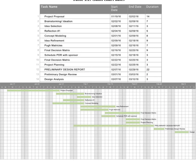
Table 1.1: Gantt chart dates
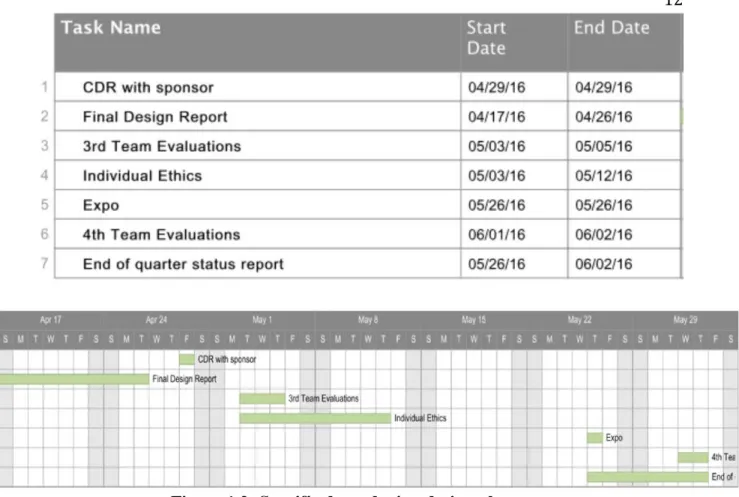
Figure 1.2: Specific dates during design phase
1.3.2 - PERT Chart
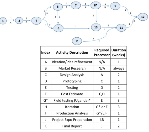
Index Activity Description Processor Required Duration (weeks)
A Ideation/idea refinement N/A 1 B Market Research N/A always C Design Analysis A 2
D Prototyping C 1
E Testing D 2
F Cost Estimate C,D 1 G* Field testing (Uganda)* E 3 H Iteration G* or E 3 I Production Analysis G*/E,F 1 J Project Expo Preparation I,B 1
K Final Report J 2
Figure 1.3: PERT chart
1.4 - Team Member Responsibilities
1.4.1 - Communication to sponsor
Omar was predominantly responsible for communication to our sponsor.
However, this does not mean that other members of the group were unable to contact the sponsor. We met with our sponsor weekly as a group, as well as communicated via email from our shared team email address ([email protected]) if we had
additional questions or topics of discussion for our sponsor in between meeting times.
1.4.2 - Secretary (documentation)
advisor. The leader of this meeting will rotate each week.
1.4.3 - Budget
Tyler managed the budget for this team. We aimed to make the product as inexpensive as possible while still attaining the designated specifications. Excluding Uganda implementation, there was
little to no travel costs associated with the design, building, and testing phases of this project so the budget will only include materials for manufacture and testing
equipment.
1.4.4 - Manufacturing Considerations
Although all members should be included in the manufacturing consideration because all subsystems need to be fabricated and fit together, the majority of the manufacturing was done by the ME students. They also have more experience using manufacturing equipment and thus know what is possible to be made with the tools available to us. It is important that all members of the group agree on a design and acknowledge that their subsystem will work with the overall plan. This includes, but is not limited to dimensioning, subsystem integration, and calculations for expected testing values to ensure the manufactured product will be safe to use. Tyler and Chris led the insulation, and heat transfer subsystems of the project. Omar was in charge of the electronic components of our design. He made sure these could be incorporated effectively into the rest of the product.
1.4.5 - Research
Chapter 2 - Background
2.1 - Market Research
After conducting research, we found that the majority of the solar cookers on today’s market use reflectors as a source of energy. When the reflectors concentrate the sun correctly, they can supply sufficient heat to thermal mass or even directly to the food. The downside of a reflection based solar cooker is that they are often large and difficult to set up. Additionally, they must be directed towards the sun correctly at all times or their efficiency will be greatly affected.
Another product that interested us is an insulated bag called The Wonderbag. These do not require solar energy to cook food, rather they utilize a traditional stove to bring food to the desired temperature then act as solely an insulator to keep this food warm. The Wonderbag is a stand-alone, non-electric insulated unit designed to reduce the amount of heating time required in the cooking of food. We aim to use the idea of
reducing heat loss by means of thick insulation around an already hot pot of food. By integrating a heating element into the insulation, we will be able to bring the food to a boil, and keep it at a simmering temperature throughout the cooking process.
The latest technology in renewable energy stoves comes from a company called Biolite Energy. The Biolite camp stove generates usable electricity for charging mobile phones and other personal devices. Burning only wood, the camp stove creates a
smokeless campfire that can cook meals and boil water in minutes. The technology works by capturing wasted heat from the fire through a heat probe. The heat is converted into usable electricity via a thermoelectric generator and sends electricity to a 5V USB port.
2.2 - Engineering Specifications
Spec # Parameter Requirements or Target Tolerance Risk Compliance
1 Weight/Size No requirement for max
weight N/A N/A N/A
2 Cost $100 ±$20 M A
3 Power 100 Watts Max L T
4 Safety
Withstand 100°C internal temperature, Outer temperature max of 56°C
Min/Max H A,T,I
5 Assembly
Assembled by no more than 2 people, using
equipment readily available in Uganda
Max M T,S
6 Maintenance Requires maintenance
less than 3 times per year Max M T,I,S
7 Operation One person can operate
completely Max M I
8 Shipping Prototype to be able to
ship to Uganda N/A M I
9 Material Effective Insulation,
cheap N/A H A,T
10 Manufacturing Manufacturing equipment
available in Uganda N/A H I,S
11 Heating
Boil 1L water in 90 mins, simmer temp throughout
day
±30
Minutes L A,T
12 Data Feedback
Log temperature readings during boil and simmer
processes
N/A M T
13 Power Control
Split power to USB port when 100W is unnecessary for cooking
N/A M T,A
These closely match the specifications set in the QFD [Appendix A]. The weight of our design is not an important specification since the cooker will be built into a home, thus it will not need to be moved. For this reason, there is no risk for the weight of our product. It will not be considered for any design decisions besides its shipping.
solar panel. The photovoltaic cells currently cost an additional $100; however, with the prices constantly decreasing this cost will be lower in the future.
In order to ensure that our product was safe we needed to design it to withstand temperatures of over 100°C without fully combusting or melting any of the components. We also wanted to ensure that people will not get burnt if they came into contact with any exposed surfaces on the cooker. According to the American Burn Association, it takes 15 seconds of exposure to open skin for an object at 56°C to severely burn you. We decided to set this to our maximum outer temperature to ensure the safety of the users. This is a high-risk specification because it could result in damaged houses or the injury of users. The outer surface temperature can be theoretically derived using our transient heat transfer model prior to testing. During testing and use, temperature will be regulated through thermocouple testing and visual inspection of the inner components after use.
We wanted the assembly, maintenance, and operation all to be relatively simple so that implementation in Uganda was feasible. A maximum of two people must be able to build a stove using only readily available tools in Africa. Low maintenance was another important characteristic. This is relatively easy to achieve considering the simplicity of design. The cooker should only require one person to operate. This means that the components such as the food and pot need to be easily removable from the cooker. These are all medium risk specifications. If not met, current Ugandan cooking methods will most likely be preferred over the solar cooker.
The material used for insulation must be low cost to ensure we stay within budget. The insulation material is fairly important because it determines the performance of our cooker under low power.Without good insulation, a 100W PV panel will not sufficiently heat water to a boil. This specification negatively correlates to cost due to the fact that manufactured insulation is typically expensive. Heat transfer analysis was used to distinguish what materials we can use and how much we will need.
Chapter 3 - Design Development
3.1 - Brainstorming
Before we began to brainstorm different ideas for designs, we looked at Dr. Schwartz’s Appropriate Technologies project. As seen in Appendix B.1, their simple design is just a bale of hay with a spot hollowed out to put the heater and pot into. This is a very basic design that does not satisfy our customer requirements and design criteria, but it gave us a foundation for brainstorming. It is discussed later in the report.
We began by looking at our engineering specifications and brainstormed different ways we could accomplish each task. All ideas were accepted no matter how outlandish in order to generate the highest quantity of designs. This brainstorming left us with many options to pursue as a first iteration. In order to determine which will yield the best results we put our designs and some intermediate elements through different decision matrices. The first matrix used in our decision process was the Pugh Matrix. We did this with different types of insulation, energy storage units, heating elements, and the loading techniques to establish our overall design.
3.1.1 - Insulation
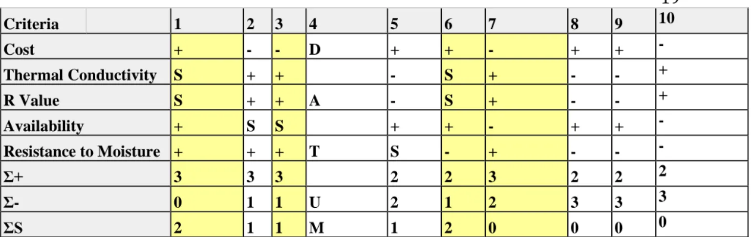
As seen in Table 3.1, we used a Pugh matrix to help us decide which insulation would be best suited for our design. By looking at our specifications we decided that cost, thermal conductivity, R-value, availability, and resistance to moisture were the most important criteria when considering insulation types. We used fiberglass insulation as our datum because it is the most common type of insulation used as well as the insulation used in last year’s project. After filling out the Pugh matrix, we found that cornhusks, mud, sand, and rock wool could be eliminated.
Table 3.1: Pugh matrix for insulation type
Concept
Rice
Hulls PS PU Fiberglass Corn Husk Hay
Spray
Criteria 1 2 3 4 5 6 7 8 9 10
Cost + - - D + + - + + -
Thermal Conductivity S + + - S + - - +
R Value S + + A - S + - - +
Availability + S S + + - + + -
Resistance to Moisture + + + T S - + - - -
Σ+ 3 3 3 2 2 3 2 2 2
Σ- 0 1 1 U 2 1 2 3 3 3
ΣS 2 1 1 M 1 2 0 0 0 0
Because our Pugh matrix was not weighted, we decided some of our results could be skewed. Although spray foam has a good thermal conductivity, R-value, and
resistance to moisture it is very expensive per unit volume. We decided to research the cost of each insulation type and graph their price per unit volume vs. thermal
conductivity. As a result of this graph, we found that spray foam and rock wool are significantly more expensive than any other type of insulation. For this reason, we decided not to include spray foam in our later analysis of insulation types despite its low thermal conductivity and resistance to moisture.
To further narrow down our insulation options, we weighted each of the criteria in a final decision matrix. Their level of importance determined each individual criteria weight. Cost was the most important factor to consider because size isn’t a constraint of ours. If a much cheaper material has a worse thermal conductivity, we can simply add more insulation rather than spend unnecessary amounts of money on expensive
insulation. Rice hulls and hay are much cheaper options than conventional insulation like polyurethane and fiberglass. All of these types of insulations have similar thermal
conductivities, so the grading on that criteria is very similar. Durability is another important factor, but not as important as cost or thermal conductivity. The durability of polyurethane was much higher than all of the other insulations, because the other
materials may be affected by water vapor released during cooking. None of the insulation types should pose a problem with our expected temperatures. The last factor we
considered in our weighted decision matrix is availability in Africa. This will make it easier to manufacture and maintain because the materials will be readily available nearby. It would also decrease the cost of insulation to use a material that is readily available.
Table 3.2: Final decision matrix for insulation type
Design
Criteria Cost
Thermal
Concept 0.4 0.3 0.1 0.2
Rice Hull 100 40 90 27 100 10 50 10 87
PU 50 20 100 30 50 5 100 20 75
Fiberglass 55 22 95 28.5 50 5 75 15 70.5
Hay 100 40 95 28.5 80 8 50 10 86.5
Concluding from our insulation final decision matrix, we are planning on using a readily available insulation in Uganda made from an organic material such as rice hulls or hay rather than a common insulation such as fiberglass or polyurethane foam. While the thermal resistance of the common insulation types was a little better, the cost of them was significantly more. Since the cost of our product is much more important than the size, we can use a slightly worse thermal conductivity that is much cheaper to achieve our desired level of insulation.
3.1.2 - Loading Technique
Another customer requirement that we brainstormed off of was how we were going to make the cooking pot easy to remove from our design. We did not want the user to have difficulty inserting or removing their food, resulting in spilling or burning
themselves on the inside of the stove. We narrowed our ideas into another Pugh matrix to look at which matched the criteria the best.
As seen from Table 3.3, the datum we used was an oven style front load, the design used for the previous insulated PV cooker. Many of our concepts could easily be eliminated from this Pugh matrix. The pulley and lever method did not meet any of the criteria better than our datum so both were eliminated. The techniques that best met our criteria were the top load with a cinch cover, the pot into a closable bag, and the insulated pot cover. These techniques were taken into consideration when we started ideating for our overall design.
3.1.3 - Electrical system
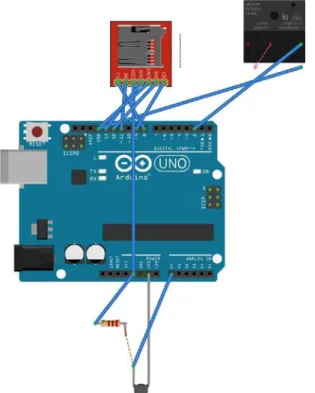
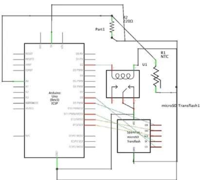
In order to test the characteristics of our solar cooker we will need several electrical components. An Arduino can be used as the microcontroller to communicate with all of the electronics. A thermocouple that is attached to the coil will send the temperature from the cooking element to the Arduino. An SD card attached to the
Arduino will keep record of the time, temperature, and voltage of the solar panel. We will be able to use this data to test different insulators for the solar cooker. We are also going to attach a relay module to the Arduino in series from the solar panel to the heating element to shut off the heating element if it becomes too hot. Once a pot of water reaches a boiling temperature of 100°C, the relay will shut off power to the heating element. Figure 3.1 and 3.2 display the physical layout and connections of the electrical components.
Figure 3.2: Schematic of testing components
3.1.4 - Energy storage
If our system is insulated well enough, we will have excess energy generated from the PV panel. We considered adding an electrical storage system to our solar cooker, but found that the additional cost of such system would put us over budget.
Figure 3.3: Charging circuit for lead-acid batteries
The charging circuit will be capable of charging two 12V 7Ah lead-acid batteries. The 1k potentiometer can be adjusted to set the desired current. We are able to calculate the charging current by performing the following calculation: Charging current =
(1/10)*14Ah= 1.4mA. The input of three of the LM317 should be at least 15V to ensure the proper voltage is provided to the charging circuit. A heat sink will be beneficial for the LM317 since it will get hot.
3.1.5 - Overall designs
Our first design concept was a “hay-bale” cooker. This is the design that the applied technologies class built and tested. As shown in Appendix B.1, the cooker consisted of a hollowed out hay bale with a mud interior lining for sizing and structural support. The heating element and pot are placed in opening and covered with a lid. A second hay bale is placed over this for further insulation. Testing of this prototype resulted in a can of beans being fully cooked over a period of 4 hours. Unfortunately, a data logger was not used during testing so specific dataset is not available. Although we do not know the specifics of this testing, it was a good assessment of the capabilities of our other designs.
The second design concept was an adaption from the “wonderbag” style that was introduced in the background section. This design is sketched in Appendix B.2. Our altered design integrates a heating element into the bag so that it will heat the food from room temperature and the maintain it at the desired cooking temperature. For this more insulation, a heating element, a thermal storage unit, and a way to replace the insulation would be required. The cloth interior will let water vapor from the food into the
insulation. This could potentially ruin certain insulations (i.e. rice hulls and hay) and they would need to be replaced semi-frequently. There will be a zipper or other type of
Our third design, shown in the upper section of Appendix B.3, was a top loading, barrel shaped cooker. Theoretically, the interior of the barrel will be hollowed out so that a pot can fit snugly into. There are actually two designs here. One has a solid cylinder in the interior for a customized pot. The other has an interior cylinder that is made of a flexible material such as fabric so that any sized pot can be used. Insulation fills the space between the interior and exterior sections. This interior section will also contain a thermal storage block made with cement and a heating element. There were a few different
designs for the top of the cooker including an insulated lid and a cinch cover.
Our fourth design, shown in the lower section of Appendix B.3, was a side
loading, oven-style cooker. This design is very similar to a conventional household oven, except with a much smaller interior section designed to fit a single pot. This also allows for more room for insulation.
These four designs were put into a weighted decision matrix to help us decide on the design that best satisfies our specifications. The criteria for the matrix was decided by looking at the engineering specification we defined in Table 2.1. Most importantly we wanted our design to be low cost so that they are affordable for people in third world countries. We weighted this to be 25% of the overall decision. Heat loss, the ability to use any reasonably sized pot (size versatility), and safety were also of concern. In order to make food boil and stay simmering with such low power we need minimal heat loss so this was weighted as 17% of our decision. Safety was weighted as 15% of our decision. We did not want to have to manufacture a customized pot for our design, instead be able to use any pot the user may already own. We weighted this at 13% because, although important, we deemed it not as important as some of the other criteria. Ease of use, manufacturability, and durability were all considered when looking at our design choices as well.
Table 3.4: Final decision matrix
As you can see from Table 3.4, of our four overall design choices, the barrel with lid and the insulated bag designs scored the highest. Because both scored similarly and are for the most part simple designs, we have decided to go forth with both ideas. Both designs will be relatively easy to build and test. Our most important criterion is cost so, creating two functional prototypes is not beyond our project budget. A solid model of the Barrel with Lid design is shown in Appendix B.4
dismiss the weight and size of the barrel. Like any other design, the major cost is the solar panel. In this design we expected the other materials to run approximately $100 or less. Our power consumption of 100W would also remain the same. The insulated barrel will be able to withstand an internal temperature of 100°C and an outer temperature of 56°C. Assembly of the insulated cooker should take less than two days with only two people.The maintenance for this design would be minimal, mainly composed of replacing insulation when it gets rotten from rain or spilled food. One person would easily be able to operate the stove. The majority of the required materials for the insulated barrel with a lid are readily available in Uganda except for some of the electrical
components which would require shipping to Uganda. The insulation for this design is dependent on what is most readily available in the region where it is implemented
The other design was inspired from a device called the wonderbag, a device that has great thermal properties. This design is the most compact of the two since it is just an insulated bag. One of the benefits of this design is that it can be easily shipped and stored if desired. We plan on inserting the heating element inside the thermal bag. The
electronics for this design would remain the same. The cost for this device would be relatively low as well since all the materials are easily attainable and cheap. Since these materials are readily available in Uganda, villagers could assemble stoves on-site. Similar to the previous design, there would be minimal safety considerations for this design. The only maintenance for this design would be for the electrical system and tearing of the outer bag. Operation for this design is relatively simple and could easily be done by a single person. Achieving boiling temperature in the desired time is dependent on the insulation and size, which can easily be adjusted.
3.2 - Preliminary Prototyping/Testing
In order to prove that we have a valid concept a rough prototype was built and tested. To simplify this, we used all store bought parts instead of fabricating any. Because our design is so simple, it was easy to vary the geometry of different parts and still be able to model our final design accurately. A brief cost analysis of all parts bought for this prototype can be seen below in Table 3.5.
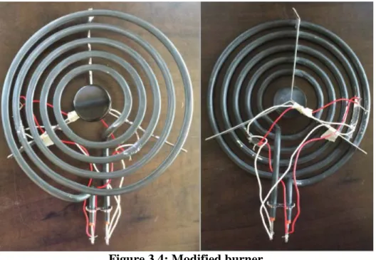
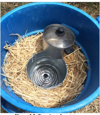
We already had the majority of these parts so there was not much additional cost required to build our first prototype. Also, in our initial test we did not implement any thermal storage or temperature sensing. Additional parts needed for this were discussed in Section 3.1.4. A large plastic garbage bin was used as the outer container. This was filled halfway with straw, which is what the inner cook chamber rested on. A 10-quart steel pail bought from Home Depot was used for the inner cooking chamber. In order to fit the 8” electric range burner we had to drill two holes in the side of the pail so that the two burner terminals were protruding from the pail. This not only allowed the burner to fit snuggly inside of the cook chamber but also made wiring and unwiring the burner from the PV panel easy. Because our burner is rated for 2100W and 240V a resistance of 27.43 Ohms was calculated using Equation 1.
𝑅𝑅 = 𝑉𝑉2/𝑃𝑃 (1)
𝑅𝑅𝑁𝑁𝑁𝑁𝑁𝑁 = (𝑅𝑅3+𝑅𝑅3+𝑅𝑅3)−1 = 𝑅𝑅9 (2)
This is much higher than our optimum resistance of 3.24 Ohms. Further analysis of optimum resistance can be seen in Section 4.10.1. In order to lower the resistance of the burner, we shorted it at the geometric thirds and rewired it to make it three separate resistors in parallel. As you can see in Equation 2 this decreases the resistance by a factor of 9 giving us a resistance of 3.04 Ohms. The modified burner can be seen in Figure 3.4.
Figure 3.4: Modified burner
Figure 3.5: Top view of prototype
Figure 3.6: Preliminary testing temperature vs. time
Due to time and sunlight constraints, this test could not be completed and the water was not brought to a boil. As you can see from the graph, the temperature increased in a seemingly linear manner from its initial temperature of 67.2 °F to 171.6 °F. Using the linear fit equation, we calculated a time to boil of about 115 minutes from an initial temperature of 70°F. This is about 1.5 times longer than our initial analysis predicted. There are several explanations to this difference. Our analysis is for a steady state system with no convection so it is not an accurate model of what is happening inside of the oven. Also, the thermal conductivity of the straw used in our analysis was 0.06 W/m*K, a value found through an experiment conducted by Shaw.This could be an inaccurate value for the insulation we used based on the actual material and how densely it was packed.
Chapter 4 - Description of the Final Design
4.1 - Overall Description
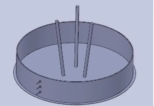
Figure 4.1: Overall design
Our overall design can be seen in Figure 4.1. Our design is very similar to the prototype we built, but is larger and has more features to make the design user-friendly and robust. The design consists of five main parts, which are generally described in this section and further laid out in the Detailed Design section. The five main parts of our design include:
1. Base
2. Outer cylinder 3. Inner cook chamber 4. Lid
user will add food in a pot to the inner cooking chamber at the beginning of the day, then slowly simmer the food until it is cooked. Our oven will not cook food quickly, but will allow the user to cook food with a minimal amount of attention after the food has begun cooking. With its simple, yet robust design, there will be little maintenance required for use. We hoped that its ease-of-use and durability will help influence Ugandan locals to fully implement it into their daily lives, solving the problem of inefficient cooking in Uganda.
4.2 - Base
Figure 4.2: Base rendering
4.2.1 - Function
The base of our design was meant to stay in the user's home permanently. It adds
4.2.2 - Components (material selection, tolerancing, etc.)
Base plate:
The main purpose of the base plate is to keep the inner insulation from being destroyed. It also gives the entire oven support because its diameter is wider than that of the oven. To minimize rusting, we chose 22-gauge galvanized steel sheet metal. Ideally this part would be thicker to give it more structure and weight. The only tolerance put on this part is a minimum diameter equal to the diameter of the outer cylinder. Having a larger diameter will only add more support. A detailed drawing of this part can be seen in Appendix C.1.
Cooking chamber supports:
Since these will be protected from the rain we do not have to spend extra money on galvanized or stainless steel. Rebar is very cheap and easy to work with so we chose to use ½” steel rebar. This will lower costs, make it easy to manufacture, and ensure that we will be able to get all of our materials in Uganda. The way these parts are designed makes them still functional if they differ in lengths and angle welded. The cooking chamber will still be able to be placed on the supports if they are different lengths. A detailed drawing of this part can be seen in Appendix C.1.1.
Outer cylinder supports:
This part must be able to be rolled and cut fairly easily so we selected 22-gauge galvanized steel sheet metal. This will protect it from rust as well. Holes must be located on the part so that once it is rolled into a cylinder it can be riveted easily. The length and height can vary by a few inches as long as its radius is larger than that of the outer cylinder. A detailed drawing of this part can be seen in Appendix C.1.2 and Appendix C.1.2
4.2.3 - Manufacturing
● Cut a 30-inch diameter circle from a sheet of 22-gauge galvanized steel ● Weld 3, 16-inch long pieces of rebar to this base plate
○ The base of these pieces of rebar should be 2.5 inches from the center of the base while the top of the rebar should be 4.5 inches from the center (radially). At this angle the interior-cooking chamber will rest on the rebar.
● Using a shear, oxy acetylene torch, or a press punch (whichever is readily available) cut a sheet of 22 gauge galvanized steel that is 96 inches by 6 inches
○ Punch 3 holes along the short edges of this sheet
■ The center of these holes will be 1.5 inches apart, and 1.5 inches from the edge of the sheet
○ Roll the sheet into a 28.66-inch diameter cylinder using a sheet metal roller, the holes should line up at this dimension
*Drawings with dimensions can be found in Appendix C.1
4.3 - Outer Cylinder
Figure 4.3: Outer cylinder rendering
4.3.1 - Function
The outer cylinder is what contains the insulation around the inner cooking chamber. It is lifted over the base and slid into the wider cylinder that is attached to the base. This will keep it from tipping over or sliding around when in use. We designed the outer cylinder to be light enough to be lifted using the handles so that the user can bring it outside or anywhere else in the house that they may want to temporarily use it. Without the base it will still stand, but will not be as sturdy so we do not intend users to
take the risk of someone cutting their hand on top of the oven as well as protect users from the pinch point between the lid and outer cylinder when closing the oven.
4.3.2 - Components
Cylinder:
The cylinder is the main component of this part of our design. It will be made of the same material, 22-gauge galvanized steel sheet metal, as the base support for the cylinder. This will allow us to roll then rivet the sheet metal easily in the same way that the base support was rolled. We were worried about the steel being too heavy for someone to lift so we chose the gauge of sheet metal based off of what its total weight would be after it is cut. With 22-gauge sheet metal this part would weigh around 26 lbs. not including the handles and vent. This is light enough for the user to be able to move this part of the oven fairly easily. We chose galvanized steel to prevent rusting as well. A detailed drawing of this component can be seen in Appendix C.2.1 and Appendix C.2.2.
Handles:
The handles are an important part of the outer cylinder because it allows the user to pick up the oven more easily in order to move it or replace the insulation. To decrease cost and ensure that we will be able to get the materials in Uganda we are going to use ½” rebar that will be bent and welded onto the sides. This is the same material used for the inner cooking chamber base supports so this minimizes the number of materials we would have to order.
Vent:
The vent will be inserted into the inner cooking chamber so it will need to withstand higher heat than conventional PVC pipe can withstand. We chose 1” CPVC pipe so that it can withstand higher temperatures without melting. CPVC is also more corrosion resistant than conventional PVC. This is important because it will be in contact with water vapor while in use.
The U-bolt is a part that will be bought off of McMaster Carr to decrease the amount of custom fabrication required. It is a 1-⅜” zinc-plated U-bolt. The zinc plating will reduce corrosion. It is sized so that it can accommodate 1” CPVC pipe easily without being perfectly aligned.
4.3.3 – Manufacturing
● The shell of this cylinder will be made from a 22-gauge galvanized steel sheet ○ Take a sheet of 22-gauge galvanized steel that is 96 inches by 30 inches ○ Punch 7 holes along the short edges of this sheet
■ The holes will be 4 inches apart, and 4 inches from the edge of the sheet
■ The end holes should be 3 inches from the top and bottom edge ○ Punch a 1.5-inch diameter hole in the center of the sheet, 9 inches from the
the bottom edge
■ This hole will be for the wires from the PV panel to the burner ○ Punch 2 0.25-inch holes 4 inches from the top edge of the sheet. These
holes should be 1 inch apart, centered at the middle of the sheet. ■ The distance between these holes is more important than the
position
■ These holes will be used to fasten the U-bolt to the shell
○ Wrap this sheet into a 27-inch diameter cylinder. The edge holes should align
○ Rivetthe holes to hold this sheet metal in the cylinder shape
○ Insert the CPVC piping and CPVC elbow through the ventilation hole ○ Fasten the U-bolt around the CPVC to hold it in place
○ Bend 2, 8-inch-long piece of ½ inch rebar on both ends, 1.5 inches from the ends
■ Weld this rebar to the sides of the steel shell, 4 inches from the top
*Drawings with dimensions can be found in Appendix C.2
4.4 - Inner Cooking Chamber
Figure 4.4: Inner cooking chamber rendering
4.4.1 – Function
wiring to the burner. Because it will not be made of metal like the outer cylinder, rubber grommets are not required for these holes.
4.4.2 – Components
Burner:
There are several different options that we have for burners. Conventional electric range burners have too high of a resistance which would greatly decrease our power (further analysis in Section 4.8.1). To lower resistance we can modify the burner so that it is three resistors in parallel, which would decrease resistance by a factor of 9.
Cook Chamber:
The cooking chamber will be either a bought or handmade part. It will be made of a ceramic, clay, or mud material depending on what’s most readily available. These materials have a lower thermal conductivity than metals so that less heat is dissipated to the insulation directly below the burner. This will also focus more of the burner’s energy on the pot and food. The chamber must be able to accommodate the burner and vent. To do this the bottom diameter must be large enough and three holes must be drilled in it.
4.4.3 - Manufacturing
The manufacture of this part really depends on what is available in Uganda. Ideally, the part would be made from a hard material with a low thermal conductivity as stated above. The ideal choice would be to buy clay or ceramic pots of a similar size if that is possible. If not, the next option would be to make a pot from ceramics, clay, or mud bricks. If neither of those options are possible in Uganda or our manufacturing facility, there then a tin bucket would need to be purchased to use for the structure of this part and an
insulating plate will be placed inside under the burner to help direct heat upwards into the pot and food rather than down into the cooking chamber and structural supports.
Once a “cooking chamber” has been decided on from the available resources in Uganda, a 1.5-inch hole will be made near the top for the CPVC ventilation. A 0.75-inch hole will be made 0.5 inches from the bottom for the wires to run through. The burner will be placed in the bottom of this chamber. If this part ends up being made from a highly thermal conductive material a ceramic plate the same size, as the bottom will be under the burner.
*Drawings with dimensions can be found in Appendix C.3.
Figure 4.5: Lid rendering
4.5.1 – Function
The lid sits on top of the outer cylinder while the oven is in use, protecting the inner cooking chamber and insulation. Underneath the lid, more insulation is attached so that when you close it the top of the cooking chamber is insulated. This makes it so the user does not have to pack insulation over the pot every time they insert or remove a pot. The casing for the insulation is made of ¼” chicken wire so that insulation doesn’t fall into the cooking chamber, creating a fire hazard. A handle was added on top of the lid to make closing and opening the oven easy. So the lid isn’t put on the ground when taken off, a hook was attached so that the lid can be hooked onto the one of the handles on the side of the outer cylinder. This will increase the life of the lid and insulation underneath it.
4.5.2 – Components
Top:
The top of the lid will be made of 15/32” treated plywood. This material is cheap and sturdy enough to withstand the loads that will be put on the lid. It is important for the lid to be water and corrosion resistant due to the wet season in Uganda so treated
plywood was our best option with greatly increasing price and weight. The top is just a circle that must have a minimum diameter of half an inch more than the outer cylinder’s diameter. In order to attach the chicken wire insulation holder underneath it, 8 series of two holes must be drilled around the perimeter of the top. This will allow the
Handle:
The handle is a purchased part off of McMaster Carr. It is a stamped stainless steel part, which will be strong enough to withstand the load of lifting the lid as well as not rust in the rain. A detailed drawing of the handle can be seen in Appendix C.4.2. The handle will be fastened using 2 stainless steel hex nuts and bolts with stainless steel washers on the underside of the lid to disperse load. The bolts are M10 bolts that are 30mm long. These are the same bolts that will be used on the hook, which is discussed next. Detailed drawings of the nuts, bolts, and washers can be seen in Appendix C.4.4 - C.4.6
Hook:
The hook selected will also be purchased off of McMaster Carr. It is a zinc plated steel hook with a 5” projection. This will prevent corrosion and give us enough hook space to easily be able to attach the lid to the handle of the outer cylinder. A detailed drawing of the hook can be seen in Appendix C.4.3. The hook will be attached using the same nuts, bolts, and washers as the handle.
Insulation holder:
¼” mesh chicken wire will be used for the insulation holder. This material is very easy to manipulate so it can be hand rolled into the cylindrical shape we have designed. It can also be cut very easily which helps with ease of manufacturing. The mesh chosen is small enough to hold the insulation without it dropping into the cooking chamber.
Zip ties:
In order to keep costs down, the mesh will be zip-tied to the lid. These will not be under much load so the zip-ties should not fail.
4.5.3 - Manufacturing
Manufacturing the lid of our solar cooker.
● Cut out a 29-inch diameter circle from a sheet of 15/32 inch treated plywood ○ Drill 8 sets of 2 0.25 inch holes around the perimeter of the circle
■ Each individual set of holes should be 0.5 inches apart ■ The sets are positioned 45 degrees in relation to each other ■ These will be used to fasten the insulation support to the lid
○ Across the diameter of the circle, drill 2, 0.25-inch holes, 5.75 inches apart ■ The center of the circle should between these two holes
■ These will be used to fasten the handle to the lid
■ The distance between the holes is more important that the position. ○ Fasten the handle to the lid using 2 M10 bolts, nuts, and washers
○ Drill 2 more holes along the edge of the circle
■ These holes will be 1 inch apart with the outside hole 0.75 inches from the perimeter.
○ Wrap the chicken wire into a 27-inch diameter by 8.5-inch height cylinder ■ Use zip ties to fasten the chicken wire to itself in this shape
● Cut a 27-inch diameter circle out of 0.25-inch chicken wire ○ Fasten this circle to one end of the cylinder using zip ties ● Fill this cylinder with insulation
● Fasten the cylinder to the lid with 8 zip ties through the perimeter holes
*Drawings with dimensions can be found in Appendix C.4
4.6 - Electrical System
In order to ensure that the coil does not overheat, we designed an electrical system to turn off the coil when it reaches a set temperature. The system consists of an Arduino that is connected to a thermocouple and also connected to a relay. The schematic in Figure 4.6 is shown below. The thermocouple will be installed by wrapping it around the heating element to ensure a proper temperature is read. This toggle temperature will be 100 degrees Fahrenheit cooler than the combustion temperature of the insulation The relay will be connected in series on the positive lead of the solar panel output.
Figure 4.6: Electrical system
4.7 - Cost Analysis
Table 4.1 below shows the itemized list of material costs. Some parts will be
manufactured in-house, while others will be bought. The parts that will be manufactured are the base plate, outer and inner supports, outer container, inner cooking container, top lid, and the lid insulation container. All other parts, fasteners, and electronic equipment will be purchased. As you can see from the table the final material cost of our design is $116.79. This does not include the cost of manufacturing, labor, and overhead. If we were to manufacture our design on a larger scale we could buy materials in bulk and decrease our total materials cost so price would most likely even out to around $100, which was the specification we set initially.
Table 4.1: Cost analysis
Part Material Price Quantity Total
- -[$/unit length] [ft],[ft^2], piece [$] Parts
Base Plate 22 ga. galvanized steel sheet metal $1.94 3.8 $7.35 Outer Cylinder Support 22 ga. galvanized steel sheet metal $1.94 4.59 $8.88 Inner Cylinder Support 1/2" rebar $0.22 4 $0.89 Outer Container 22 ga. galvanized steel sheet metal $1.94 18.75 $36.28
Inner Cook Chamber Ceramic/clay/mud 1 $0.00
Lid Top 15/32" treated plywood $0.84 7.6 $6.36 Insulation Holder on lid 1/4" chicken wire $0.90 10.5 $9.42 Outer Container Handle 1/2" rebar $0.22 1.33 $0.30 Lid Handle Stamped stainless steel $6.00 1 $6.00
Hook Zinc plated steel hook $4.80 1 $4.80
Vent 1" CPVC $1.91 1.67 $3.19
Vent Elbow 1" CPVC elbow $2.47 1 $2.47
Rubber Tubing 1/2" rubber pipe insulation $0.63 15.2 $9.50 Rubber Grommet 3/4" rubber grommet $0.14 1 $0.14
Fasteners
Rivets 1/4" stainless steel rivets $0.50 10 $4.96
U-bolt 1-3/8" zinc plated $1.30 1 $1.30
Zip ties 8" plastic zip ties $0.02 16 $0.32 Bolts M10 30mm stainless steel hex bolts $0.73 4 $2.93 Nuts M10 stainless steel hex nuts $0.39 4 $1.57 Washers M10 stainless steel flat washer $0.12 4 $0.49
Electronics
Adjustable knob temperature
control $9.65 1 $9.65
Ibutton Borrowing data logger N/A 5 N/A
Burner 6" electric range burner $10 1 $10.00 16 gauge wire 16 ga. insulated wire $0.30 10 $3.00
PV Connectors Plastic $1.43 1 $1.43
Some assembly will be required once it is manufactured. If there is no insulation at hand in the manufacturing facility, then the user must use their choice of insulation for the lid and zip tie it shut. This process is the same for the user as it would be for the manufacturer, so this process can be seen again in Section 4.5.3. Other than that all assembly instructions are below:
1. Place base where you will cook the majority of the time
2. Lift outer cylinder over base and slide it inside of the cylinder welded to the base 3. Densely pack the outer cylinder with straw (or any other form of insulation at
hand) until it is up to the wire hole
4. Place inner cooking chamber on the stand inside the cylinder
5. Put PVC pipe vent into inner cooking chamber hole and attach the other end to the elbow
6. Thread wires through the wiring hole and connect them to the connectors on the electronics box.
7. Fill the rest of the space with insulation until it is level with the top of the inner cooking chamber
8. Place lid on top
4.9 - Maintenance
The main worry regarding maintenance is the failure of the electrical system. In order to decrease the likeliness of failure we designed the electrical system to be as simple as possible. If, after testing, we conclude that an Arduino data logger is not
necessary we can always use a bimetal switch that is only one small part. This will be less likely to be tampered with too.
Maintenance may need to be done on the insulation in order to keep it from rotting. Further testing must be done to figure out how often this maintenance will occur, but it will most likely need to be changed during the wet season. We designed the oven to protect the insulation as well as possible and also to make changing out the insulation easy. The user will have to cut the zip ties on the bottom part of the chicken wire
underneath the lid to get the insulation out. Once removed, they can pack new insulation and zip-tie it together.
4.10 - Engineering Analysis
4.10.1 - Optimum Resistance
calculated an optimum resistance using two methods. The first involved using the “Electrical Characteristics” graph given by Eco-Worthy, the manufacturer of the solar panel. As seen in Figure 4.7, the power curve given by the manufacturer can be analyzed graphically in order to calculate an optimum resistance.
Figure 4.7: Power curve of PV panel
The power is maximized at the point chosen in the Figure 4.7. The current and voltage was obtained from a point on the graph and the optimum resistance of 3.05 Ohms was calculated by equation (4.1).
𝑅𝑅 = 𝑉𝑉𝐼𝐼 = 518.9𝑉𝑉𝐴𝐴= 3.05Ω (4.1)
Another method was used to calculate an optimum resistance. As seen in Figure 4.8, by modeling the PV panel as a voltage source with a resistance and our burner as a single resistor attached in series to the PV panel you can easily calculate when the load resistance optimizes power.
Figure 4.8: PV simple electrical model
This circuit is then analyzed and found that power is maximum when Rs = RL.
In Equation (4.5), the load resistance is calculated which, according to Equation (4.2), needs to be maximized to maximize power. Equation (4.6) differentiates the denominator of Equation (4.5) to find the minimum. This will maximize the load
resistance. As you can see from Equation (4.7) the maximum load resistance is when it is equal to the source resistance. To find the source resistance, we took maximum power characteristics of our solar panel, which were given by Eco-Worthy. This calculation can be seen in Equation (4.8) below.
Figure 4.9: Standard solar panel power curve. The operating points for each curve at its optimized resistance are indicated with black open circles while the operating points of each curve at our chosen resistance are highlighted by red dots. Power is
equal to the area of an inscribed rectangle defined by the operating points
We have performed a steady-state heat transfer analysis on a model of our design. The cooker is modeled as a cylinder with a hollow center and ventilation. A
1-Dimensional heat transfer in the radial direction was calculated at steady state to
determine the heat loss with different insulation types and sizes. This calculation can be seen in Appendix D. The model is assumed to have an internal temperature of 100 °C (the boiling temperature of water) and an external temperature of 25 °C. All sizes are estimates, and can be changed depending on necessary insulation and packaging constraints. These sizes, as well as thermal conductivities, and temperature differences can be adjusted in the excel sheet. Our heat transfer calculations tell us how much heat (in Watts) will be theoretically lost through the insulation and thus is the minimum heat required to boil at steady state.
We took the sizes and chosen insulation to model this heat transfer in a finite element analysis (FEA) for our final design. The model is shown in Figure 4.10 and analyzes the insulation for the cooker. The interior cylinder is held at a constant temperature of 100°C to simulate boiling water while the outside edge is subject to natural convection at 25°C and a convection coefficient of 25 W/m2K. The bottom of the
interior section models the burner where 100W of power is introduced to the system from the solar panel. This FEA model shows a very high temperature region just below the burner. We decided to add extra insulation of a non-flammable material (such as clay or ceramics) below the burner to help prevent the straw below the burner from getting this hot because it’s combustion is less than is shown in our FEA model. We don’t expect the solar cooker to ever actually get this hot though for a number of reasons. This model is at steady state which means it has been running for an infinite amount of time. Our cooker will run a maximum of 12-14 hours per day simply based on the hours of sunlight. Also, during the time that the cooking is running, we will not always be getting 100W of power out of the PV panel. Full power will only be received during peak hours of the day
Figure 4.10: FEA heat transfer model
4.10.3 - Transient Thermal Modeling
Transient modeling requires a computer mesh analysis and iteration at every point of the insulation. However, it may be more instrumental to use a simplified
cylindrical model to represent our system. We use the thermal resistance equation (eq. 4.9) where P is the rate of heat loss; is the difference in temperature between the inner and outer surface; and R is the thermal resistance.
(4.9)
𝑃𝑃
=
∆𝑇𝑇
𝑅𝑅
We model the heat flowing through the insulation in three sections: The cylindrical wall and the two discs above and below the cooking chamber (Fig. 4.11). The cylinder is approximated as a section from an infinitely long cylinder yielding a resistance of:
thermal resistance; λ is the thermal conductivity of insulation material, and L is the
length of the cylinder.
Figure 4.11: Cylindrical geometry for heat loss analysis
Similarly, we can estimate the insulation end pieces as solid disks of radius r2 and
thickness l, which we set equal to the cylindrical wall thickness (r2 - r1), yielding the
resistance,
(4.11)
𝑅𝑅
=
𝑟𝑟
2− 𝑟𝑟
1𝜋𝜋𝜋𝜋𝑟𝑟
22
Thermal resistances are added by taking the inverse of the sum of the inverses. The three sections of insulation combine to give a total thermal resistance of 0.213 K/W, with an inner radius of 0.1778 m, an outer radius of 0.2875 m, and estimated
thermal conductivity of 0.06 W/m-K for straw. These equations are used to calculate the rate of heat loss (eq. 4.9).
Heating
Our computer model calculates the temperature of the chamber every minute, assuming uniform temperature of the contents and of the outside environment.
The amount of energy present in the system is used to find the difference in temperature between the inside and outside of the insulation. By subtracting the heat loss (eq. 4.9) from the power provided by the solar panel, the amount of energy is updated to the next time increment:
(4.12)
𝐸𝐸𝑛𝑛 =𝐸𝐸𝑛𝑛−1+ (𝑃𝑃𝑖𝑖𝑛𝑛− 𝑃𝑃𝑙𝑙𝑙𝑙𝑙𝑙𝑙𝑙) ×𝑡𝑡𝑙𝑙𝑠𝑠𝑁𝑁𝑠𝑠
Where En represents the energy in the chamber at a certain moment in time; En-1
solar panel; Ploss is the heat loss rate (4.9); and tstep is the time between calculations.
∆T is found from the equation 4.13.
(4.13)
𝐸𝐸𝑛𝑛 =𝑚𝑚𝑚𝑚∆𝑇𝑇
Manipulating equation 4.13 to further suit our model, we can solve for the temperature change using equation 4.14,
(4.14)
∆𝑇𝑇
=
𝐸𝐸𝑛𝑛(𝑚𝑚𝑚𝑚)ℎ20 + (𝑚𝑚𝑚𝑚)𝑚𝑚𝑚𝑚𝑚𝑚𝑚𝑚
where En is the total energy from equation 4.12; m is the mass; and C is the specific
heat. The denominator is separated into 2 parts, one for the water that is being heated, and another for various other masses that are present in the system. These include potential thermal storage, the pot, and any interior structure of the cooker. This model will be used later on to compare our results during testing.
4.11 - Safety Considerations
Safety is very important in the implementation of photovoltaic cookers in Africa. One of the main reasons for this project was to increase the safety of cooking; we need to ensure that our method is much safer than previous methods. Since we have removed the harmful emissions from conventional cooking methods, it should already be relatively safe, however there are some other safety factors to consider now.
One safety consideration is the combustion of our insulation. As shown in Figure 4.10 above, there is a hot region just below the electric burner. This region in our steady state model is at a higher temperature than the combustion temperature of many of our possible insulated materials such as straw and rice hulls. Obviously the temperatures shown in the figure are exaggerated because they imply that 100W of power will be heating the cooker at all times and it does not take into account that it will cool down overnight. In case the interior temperatures below the burner still do reach near
combustion temperatures, we plan on using a non-flammable insulation directly below the burner such as ceramics, clay or mud bricks in order to dissipate some of the heat before it reaches the bulk of the flammable insulation. Additionally, a thermocouple controller or temperature dependent switch will be implemented below the burner. This controller will turn off the power from the PV to the burner or simply open the circuit so no power is provided and the temperature of the insulation will be allowed to decrease. During normal use of the cooker this should not be an issue because the water boiling will keep the interior temperatures near 100℃. If left on with no water inside the cooking chamber however this could quickly become a safety hazard.
chamber. If a finger gets caught between the lid and shell while placing (or removing) the lid on the cooker the weight combined with the sharp edge of the shell could easily cut it. To combat this issue, we added rubber tubing along the top edge of the shell.
A third issue we considered was removal of the pot after cooking. This pot will contain food still at or close to 100℃ because the food inside has been simmering. It is important that the user can remove the pot without burning themselves. We explore a number of options to prevent burns including different handles and a device to remove the pot with. Ultimately we decided that the most reasonable way to fix this issue was to simply have the user wear oven mitts or let the pot cool to a temperature that will not burn them before removing. Currently people in 3rd world countries are cooking over a 3-stone fire. The handles from the pot will be significantly hotter in their method than ours anyways and they already can remove the pots from the fire without burning themselves. It would not be cost effective for us to implement a method of removal of a hot pot when a cheaper alternative is available.
Our final safety consideration was the fraying of the wires from the PV to the burner. These wires are threaded through a fairly small hole in our sheet metal shell. Similar to the pinch points discussed above, we aim to prevent the wires from being cut by this sharp edge. A rubber grommet is inserted into the wire hole in order to prevent wire fraying at the contact point with the outer cylinder.
Chapter 5 - Product Realization
5.1 - Developing World Design
Upon completion of our previously stated design, we realized that it was much too expensive for our third world application. It would be more effective to create a cooking unit that is much simpler and be able to implement more of them with the money we had. The only necessary components are a solar panel, insulation, and a heating element. The solar panel and insulation are already as cheap as they can possibly be (unless solar panels are donated), however the heating element can be made cheaply, and the structure of the cooking unit is unnecessarily robust. Our prototype greatly differs from the
previous design to lower our costs and will be shown in the section below.
5.2 - Manufacturing Process
5.2.1 - Custom Heating Element
A heating element is simply a resistor. We had previously planned on purchasing traditional stove top heating elements, but it could be much cheaper and more efficient to build them ourselves. This allowed the flexibility to choose resistance and shape as well. We used 26-gauge Nickel-Chromium (NiCr) wire (which has a standard resistance of 2.67 ohms/foot) immersed in a concrete tile ½” thick. The left portion of Figure 5.1 shows the wire woven into our mold. The right side of Figure 5.1 shows two finished burners. Note, wires should be clamped together rather than soldered because the solder will melt during burner use.
Figure 5.1: Nickel-Chromium Heating Elements. Resistive Nickel Chromium wires are held into place in a mold (left). After concrete hardens, the finished heaters can