Trellis Coding based on RLLPUM Codes for RFID Reader-to-Tag Channel
Vijey Thayananthan, Ahmed Alzahrani & Muhammad Shuaib Qureshi
Department of Computer Science, Faculty of Computing and Information Technology, King Abdulaziz University, Jeddah 21589, Kingdom of Saudi Arabia.
Abstract: Trellis coding techniques are simple graphical methodology in the encoder and decoder development in information theory. When this technique is applied to partial unit memory code (PUM) code, minimal trellis designs with less complex approach are identified using Shannon product theory. Combination of run-length limited (RLL) and PUM codes is called RLLPUM code, which is applicable to digital magnetic recording channels. Radio frequency identification (RFID) system contains reader-to-tag channel, which has similar properties as used in digital magnetic recording channels. In this paper, error detection and correction are considered with trellis coding techniques based on RLLPUM codes. Data storage is challenging topic with other competing technologies which provide a number of benefits. We propose a technique that allows the design of PUM codes with balanced RLL properties influenced with RFID reader-to-tag channel. From the results, error detection, correction and storage, which could be increased up to 50%, are compared.
Key words: Trellis coding, RLLPUM codes, RFID, Balanced codes, Reader-to-tag channel INTRODUCTION
TRFID system has tag and reader which is the only main source of energy that allows passive tags to store data. Using RFID tags, reasonable size of data can be stored, but they can be extended with bigger storage capacity with some modifications. The RFID tag, which has many types, is used in different applications. Data need to be corrected before they are stored in the tag, so proper error control technique should be employed in the reader-to-tag channel. PUM error control code is chosen because both error correcting capability and storage capacity needs to be improved in the RFID channel. Using networked RFID system, stored information or message could be sent to all over the places through the high-speed network linked within the fraction of the second if RFID channel is reliable. Most of the medical and business applications are involved with data storage; therefore, RFID system is modified to use as data storage. RFID’s potential demands encourage me to explore this research which provides better storage capacity without changing the bandwidth. In this paper, data storage of RFID reader-to-tag channel based on RLL/PUM coding will be considered with trellis design.
Trellis design is constructed from Shannon product discussed by Ke et al. (1995) helped to reduce complexities and increase the decoding facilities. In PUM and RLLPUM coding schemes, trellis approaches are popular coding techniques because minimal trellis construction depends on the free distances of PUM coding. In order to increase storage capacity in reader-to-tag channel, PUM code is chosen because this channel has similar properties as digital magnetic and optical storage devices. RLLPUM code is already proved to improve the above mentioned channels. In the reader-to-tag channel, inductive coupling of RFID is introduced to transfer the energy helped for information transmission mentioned by Angela et al. (2010) RFID reader needs attached power but tag can be used without separate power. In this paper, lower layer coding of information on inductively coupled channels is introduced with PUM error control coding. Regarding the encoding schemes specified in communication standards for RFID applications including data storage, general communication protocols, such as NRZ, Manchester, Unipolar RZ, and Miller coding are useful. Coding schemes for the reader to tag channel depend on RLL and other coding constraints, Manchester code, variable code etc. Abdel-Ghaffar et al. (1991). RLL codes are used to transform the digital user bit stream into a sequence of binary channel symbols that are suitable for the specific storage requirements. The runlength is known as the number of consecutive identical symbols occurring in a sequence.
This correspondence is organized as follows. In the next section, we describe the trellis of PUM codes and introduce the basic procedure for construction. In section 3, design of both the balanced and RLLPUM codes is described. The details of the proposed system are described. In section 4, a regular trellis design procedure is briefly outlined. In section 5, results of PUM and RLLPUM codes are presented for the proposed codes and finally, in section 6, the conclusions are given.
The PUM error control codes were invented in late 1970, but its applications were not popular at that time because the technology wasn’t powerful as we use them in potential applications. The (N, K) unit memory codes use fixed delay t during the encoding. When delay is less than information length (t < K), it is called PUM code (Lee,1976; Thommesen and Justesen, 1985). Initially, it was used it for digital magnetic recordings. It is basically an error control code which provides best free distance properties. In this paper, linear PUM codes are chosen as a technique because its data rates for RFID storage are very useful in potential RFID applications. Further, it has both block and convolutional code properties. It has a lot of advantages such as variable rates, best performance, storage capacity etc. but we need to optimize the complexities which could be the main disadvantage.
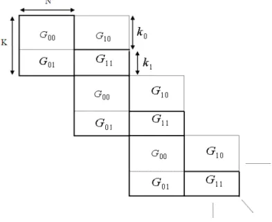
Fig. 1: Basic idea of PUM code.
As shown in Fig. 1, the generator matrix can be organized for PUM code. Each matrix in this Fig.1 is explained in the next section.
Linear PUM codes were proposed as a method of using the theory of block codes for construction of new convolutional codes (Markarian, Honary, 1994; Markarian et al. 1997). These codes combine advantages of both block and convolutional codes may be described as (N, K) convolutional codes with memory v=1. It has been shown that there are PUM codes with the free distance at least as large as those of convolutional codes with the same information rates and constraint lengths (Thayananthan et al. 1998). Compared with the block codes, the PUM codes have the highest possible code dimension K for a given code length N and free code distance
d
free (Shraga, 1995). For instance, the best known block code with encoded block length n = 8 bits, information length k = 4 bits and the minimum Hamming distanced
min = 4 is considered. The PUM code chosen with same encoded length N = n = 8, free distanced
free = 4 and information length K = 6 provides 50% increases in the information rate. In addition, the byte oriented nature created from PUM encoder makes them particularly attractive in storage channels such as digital magnetic recording and RFID. It is anticipated that the application of PUM codes in magnetic and optical recording systems could provide a significant increase of the recording density without expensive technological advances. However, known PUM codes may not be applicable in the RFID reader to tag channel because they do not satisfy thed k
0 0 and the RDS constrains thus they are not applicable to magnetic and optical recording channels. In this correspondence, we introduce a technique that allows the design of the high-rate RLL and balanced error control codes based on PUM codes. We can also show that the maximum-likelihood decoding of these codes can be achieved with regular trellis structure. Trellis coding technique based on RLLPUM is introduced for RFID reader-to-tag channel.Details of the Proposed System:
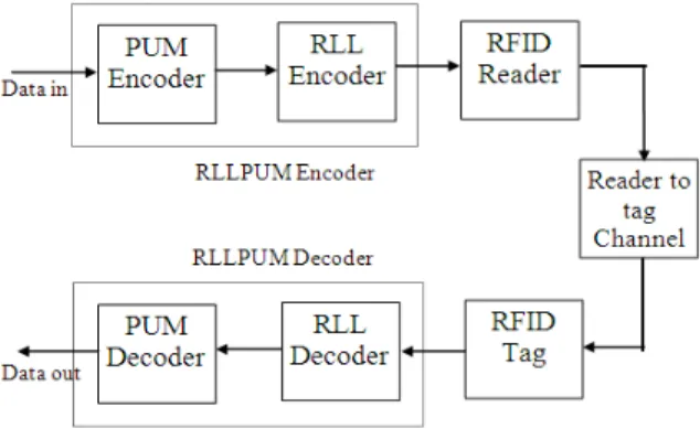
Fig. 2: Block diagram of RFID system with RLLPUM coding.
We propose a technique that allows the design of PUM codes with some special characteristics, which corporate with balanced and RLL properties. According to the properties, the designed code can be used in the RFID channel known as a reader to tag channel.
Traditionally, many communication systems, such as digital magnetic and optical storage devices, fiber-optic and cable telecommunication systems, employs the dc-free constrained codes (often referred to as recording or modulation codes) which transform the input data stream to a waveform suitable for the specific channel requirements (Henrici et al. 2010). The term constrained code comprises the two particular types of codes, known as the RLL and balanced codes. The RLL codes, also defined as the
d k
0 0 constrained codes, represent a class of codes in which the two consecutive ones are separated by at leastd
0 but no more thank
0zeros. The parameter
d
0 is used to control the inter symbol interference between recorded transitions while thek
0 parameter imposes a maximum number of zeros that are required for self-clocking purposes. The balanced codes represent a class of constrained codes with the limited value of the digital running sum (RDS) (Markarian et al, 1997). Problems connected to the design of both the RLL and balanced error control codes (ECC) have received considerable attention, and a great number of block and convolutional ECC constrained codes have been designed. However, the ever existing demand for higher recording densities dictates the need of higher information rates that cannot be achieved with the conventional block and convolutional encoding techniques. Construction of PUM Codes:Let x1,x2,....xi,.. be the sequence of information vectors of length k, where index notifies the time interval i = 1, 2.... Let y1,y2,....yi,.. be the sequence of output code vectors of length n. The PUM encoder is given as;
... 3 , 2 , 1 *
* 0 1 1
x G x G i
yi i i (1) Where
G
0 andG
1 are the KN matrices respectively. In equation (1), rank ofG
0 = k. They are parts of the generator matrix defined as Fig. 1. Matrices are such asN K G G G
01 00
0 (2) and
N K G G G
11 10
1 (3)
In equation (2), G00 is a generator matrix of the (n, k, dmin) basic block code. In equations (2) and (3), 01
G and G11 are the
k
1
n
matrices respectively. In equation (3), rank of G1 depends on G11(rankG11 = .... 01 00 11 01 00 11 01 00 G G G G G G G G
G (4)
In order to analyze the research, PUM (8, 6, 4) code is illustrated. To design a generator matrix for this code, following matrices are used.
0 0 0 1 0 1 0 0 0 0 0 0 0 0 1 1 0 0 0 0 0 0 0 0 0 0 0 0 0 0 0 0 0 0 0 0 0 0 0 0 0 0 0 0 0 0 0 0 1 1 0 0 0 0 0 0 1 0 0 1 0 0 0 0 1 0 1 0 1 0 1 0 1 1 1 1 0 0 0 0 0 0 1 1 1 1 0 0 0 0 0 0 1 1 1 1 1 0 G G
It has been shown in (Boli´c et al. 2010) that a significant performance improvement and complexity reduction can be achieved if the PUM code is constructed based on the
(r, m) Reed-Muller (RM) codes. In order to construct the
(r, m) RM code, equation (5) is used as follows. ) ( ... ) ( ) ( ) , ( 1 0 m G m G m G m r G r (5)
Where r is the order of the code, G0(m) is the all “1s” row matrix of length2m, Gi(m) is m2m a matrix and the minimum code distance of the code ared(r,m)2mr. The corresponding PUM/RM code can be constructed from following equations (6), (7) and (8).
)
,
1
(
00G
r
m
G
(6)In equation (6), r = 4 and m = 2 can be substituted. The top row of G0in PUM (8, 6, 4) is different, because it is optimized to reduce the complexity, but minimum distance would be same.
)
(
01G
m
G
r(7)
) ( ˆ 11 G m
G r (8)
Where,
G m
r( )
matrix is obtained fromG
r( )
m
by interchanging the columns. From equation (9), free distance of such a code can be estimated as:
) , ( 2
2 1 d rm
dfree mr (9)
In this paper, free distance is considered as same as the minimum distance (dfree = dmin = 4) of PUM (8, 6, 4).
As mentioned above, the PUM code is constructed using convolutional and block codes which depend on order of Reed-Muller block code implemented from is based on denoted by (2k)
Construction of Balanced Codes:
In this paper, selected (8, 6, 4) PUM code is used for designing balanced and RLL PUM code. It has unique properties such as byte orientation, which allows the design to implement the suitable balanced and RLL/PUM code for digital magnetic channel. From the recent research, these balance code can be used in RFID channel. Further, this development can be applied to nanotechnology storage systems such as nano-optical disc and nanocomputers. PUM codes can be proposed for future communication applications based on RFID or nanotechnology.
Assume that x1,x2,....xi.... and y1,y2,....yi.... are information vectors and encoded output vectors respectively. Here, length of information vector xi{xi1,xi2,....xik}is k and length of encoded vector
} ,.... ,
{ i1 i2 in
i y y y
y is n respectively. The RDS before the p-th symbol in the i-th code word is defined as follows (M. Boli´c et al. 2010),
1
1 1 1
) 2 1 ( ) 2 1 ( i
j n
l
p
l
jl jl
p
i y y
w (10)
To determine thewip, only encoded outputyi1,yi2,....yinare applied in equation (10). The sign of this symbol is very important in RFID channel.
As in equation (11), sign is used at the end of the i-th code word as: i
n i p
i w w
w
Let the encoding procedure defined as:
) (
1 1
1 1
0
i i N i
i xG x G sign w
y (11) Where 1N is a vector, which has N ones.
Trellis Coding of Rll/Pum Code:
Similar to the balanced PUM codes, the minimal trellis for the RLL/PUM code can be easily obtained from the minimal trellis of the parent PUM code. This could be achieved by a simple alteration of the trellis branches, according to the chosen modification vector, M. In this case, the trellis design procedure is as follows:
(1) Design the trellis diagram of the parent PUM code, by using any conventional technique
(2) In the designed trellis change the labelling of all branches according to the chosen modification vector, M: M
P PiRLL}{ i} {
(12) Where
P
iRLL andP
i represent the i-th path in the new and the parent trellises, respectively.Trellis Construction of (8, 6, 4) RLL/PUM Codes:
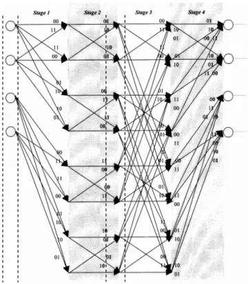
Let our aim be to design a regular trellis for the (8, 6, 4) RLL/PUM from the previous sections. The procedure to calculate the Shannon product of component trellises is illustrated in the (Ke et al. 1995), and the minimal trellis of the parent (8, 6, 4) PUM code is also shown by (Thayananthan et al. 1998). From the chosen modification vector M = (00010001) and equation (12), the trellis diagram of the designed (8, 6, 4) RLL/PUM code will have the same state and branch profiles with altered labels of trellis branches.
As shown in Fig. 3, trellis is modified to RLL/PUM code, which few changes from original trellis of PUM coding. In RLL/PUM case, second bit of stage 2 and 4 (within indicated dashed lines) is inverted according to the modification vector.
Given (N, K) PUM code with generator matrix
G
PUM
[
G G
0 1]
explained in the previous section, by using the following three concepts, we can determine the minimum following values. They are attainable forR
endi ,R
startl andR
midj , which we will denote MinimumR
endi , MinimumR
startl and MinimumR
midj , for any coset of the PUM error control coding, and hence set a lower bound on the maximum runlength for the partial code.RL
max = MAX{R
midj , Rendi + Rstartl } (12) =MAX{4, (3 + 3) }Fig. 3: Trellis diagram for (8, 6, 4) RLL/PUM code (Ke et al. 1995).
Where, upper index indicates different states of the encoder in the PUM code.
From the above concept, we can determine the RLL properties which depend on parameters (d0,k0)for the (8, 6, 4) PUM code. According to RLL theory, parameters of RLL are verified through the test and tabulated in Table 1, where some selected RLL/PUM codes are considered. RLL parameters of (8, 6, 4) code can be represented as (d0,k0) = (0, 6). Value k0 RLmax 6can also be calculated from equation (12).
First and Repeating Trellis of RLL/PUM Codes:
As far as the software and hardware designs are concerned, the repeating trellis diagrams are very important in the PUM codes. This repeating trellis structure can also be applied as a first trellis diagram when the first state of repeating trellis is considered. Further, they can be utilized to select best path out of the surviving paths that detect and correct error in the RFID reader-to-tag channel. This repeating trellis structure is simply altered according to the type of modification vector. As shown in Fig. 3, first and repeating trellis of (8, 6, 4) RLLPUM code require alteration in stage one and stage three. In order to complete the simulation, first and at least one repeating trellis must be used but first and three repeating trellises are the best option in the decoding.
Trellis Decoding of RLL/PUM Codes:
The error correction for RFID reader to tag channel is considered with trellis coding where correct path is selected for decoding. The decoder program also is written individually for each stage. From the final stage of the final depth metric calculation, the minimum path is selected. In each window, the first depth is taken as corrected path; the remaining next three depths will be moved to the next window. This final path picks up the decoded output which should be one out of 256 possibilities. The each label of the stage has 2 encoded bits. Each state has 64 different weights, which is very useful and easy to compare the path identification. Corresponding path identification and weight for given information bits produces the decoded output with 1 error correction. Further, the error correction is depended on the free distance as well metric calculation in the trellis. So, it will be increased with the increasing depths (Angela et al. 2010).
added and compared in this channel. Trellis decoding algorithm increases the error correcting capability and bit error rate (BER) performance when four trellises are used in a single window. Constructed trellis design for (8, 4) PUM code has 256 code words represented by trellis path or branches. These 256 code words are used here to select the minimum distance and path.
Results:
In order to increase the data storage in RFID tag, PUM coding is better than other known block codes. From the trellis diagram, complexity can be compared straightaway. The top part of the trellis diagram in (Angela et al. 2010) can be considered as (8, 4, 4) block. In terms of complexity, (8, 6, 4) PUM code is 4 times higher than (8, 4, 4) block code. Performance of these two codes are almost equal; therefore, it is still better for storage than block code. Using this specific PUM code, 50% of data can be stored as an enhancement without changing bandwidth.
0 1 2 3 4 5 6 7 8 9 10
10-7 10-6 10-5 10-4 10-3 10-2 10-1 100
P(b) Against Eb/No for (8,6,4)PUM Code
Eb/No(dB)
P
ro
b
a
b
ilit
y
o
f
b
it
e
rr
o
r
hard soft uncoded
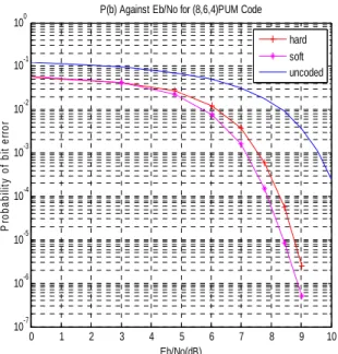
Fig. 4: BER performance of (8, 6, 4) PUM coding.
Comparison of uncoded and coded hard and soft decision curves illustrate the error performance. From the Fig. 4 and Fig. 5, we know in which direction the waterfall-like curves more corresponding to BER performance improvement. As expected, the unquantised (or hard decision decoding) trellis decoding has more than 0.5dB coding gain over the soft decision.
A high speed of reading is of attractive for many RFID applications. High-speed reading is interrupted by number of things such as collisions when too many RFID readers are involved, unwanted errors introduced during the reading etc. In order to maintain the high data quality, BER and data transfer rate are important. Error Detection in RFID:
The RFID reader-to-tag channel needs some kind of error detection and correction techniques because noise based on inductive influences of transformers in RFID system should be removed.
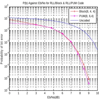
Comparison Between Block and PUM Coding:
As shown in Fig. 6, BER performance of block and PUM codes is compared through the simulations. They are almost same, but the complexity of (8, 6, 4) PUM code is four times higher than the basic block (8, 4, 4) code. It is obvious because code rate is high. So, in order to increase the storage capacity in RFID tag without changing the bandwidth, (8, 6, 4) PUM codes can be used.
RLLPUM Coding Selections:
0 1 2 3 4 5 6 7 8 9 10 10-7
10-6 10-5 10-4 10-3 10-2 10-1 100
P(b) Against Eb/No for (8,6,4)RLL/PUM Code
Eb/No(dB)
P
roba
bi
lit
y
o
f
bi
t e
rr
o
r
hard soft uncoded
Fig. 5: BER performance of (8, 6, 4) RLLPUM coding.
0 1 2 3 4 5 6 7 8 9 10
10-7 10-6 10-5 10-4 10-3 10-2 10-1 100
P(b) Against Eb/No for RLL/Block & RLL/PUM Code
Eb/No(dB)
P
robabi
li
ty
o
f
bi
t e
rr
o
r
Block(8, 4, 4) PUM(8, 6,4) Uncoded
Fig. 6: BER performance of RLL/block and RLL/PUM coding. Table 1: RLL parameters of some selected codes.
(N, K,
d
free)RLL/PUM Code RLL Parameters (d0,k0)(8, 4, 4) (0, 6)
(8, 4, 6) (0, 6)
(8, 4, 8) (0, 6)
(8, 6, 4) (0, 6)
(16, 4, 13) (0,10)
(16, 4, 16) (0,10)
(16, 5, 14) (0,12)
(16, 5, 16) (0,14)
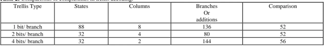
As shown in Table 2, three different types of trellis configurations have been investigated thoroughly. In this investigation, trellis design with 2 bits per branch is chosen because selected trellis coded technique has less complexity. From the investigations, the trellis decoding complexity can be tabulated as:
Table 2: Comparisons of complexities in trellis decoding.
Trellis Type States Columns Branches Or additions
Comparison
1 bit/ branch 88 8 136 52
2 bits/ branch 32 4 80 52
4 bits/ branch 32 2 144 56
Trellis design for (8, 6, 4) RLLPUM code is investigated as in (Sidorenko et al., 1996; Angela et al., 2010). Conclusion:
In this research, storage capacity can be increased at least 50%. This increment purely depended on the selection of the PUM coding rate. If (8, 6, 4) PUM/RLL code is used instead of ordinary (8, 4, 4) block code, we can have better performance and 50% storage increment without expanding the bandwidth. In RFID technology, the (8, 6, 4) code is very attractive because it has byte orientation. It means that signal processing would be better than other block codes. Generally, there is a trade-off between performance and decoding complexity.
REFERENCES
Abdel-Ghaffar K.A.S., H. Weber, 1991, Bounds and constructions for run length limited error control block codes, IEEE Trans Inform. Theory, IT-37(3): 789-800.
Angela, I.B., Eirik Rosnesz, Guang Yangz and Øyvind Ytrehus, 2010. Constrained Codes for Passive RFID Communication, Department of Informatics, University of Bergen, N-5020 Bergen, Norway.
Boli´c, M., D. Simplot-Ryl and I. Stojmenovi´c. Eds., 2010. RFID Systems: Research Trends and Challenges. Wiley.
Dettmar, U. and S.A. Shavgulidze, 1992. New optimal partial unit memory codes, Electron Letter., 28: 1748-1749.
Dettmar, U., and U.K. Sorger, 1993. New optimal partial unit memory codes based on extended BCH codes, Electron Letter., 29: 2024-2025.
Henrici, D., A. Kabzeva, T. Fleuren and P. Muller, 2010. Data storage in RFID systems. Radio Frequency Identification Fundamental and applications bringing research into practice. Croatia, 252-266.
Ke, I. and M.W. Marcellin, 1995. A new construction for n-track (d, k) codes with redundancy, IEEE Trans. Inform. Theory, 41(4): 1107-1115.
Lauer. G.S., 1979. Some optimal partial unit-memory codes, IEEE Trans. Information Theory, 25: 240-243.
Lee, L.N., 1976. Short unit-memory byte oriented binary convolutional codes having maximal free distance, IEEE Trans. Inform. Theory, 22: 349-352.
Lee, L.N., 1977. Concatenated coding systems employing a unit-memory convolutional code and a byte-oriented decoding algorithm, IEEE Trans. Communication, 25: 1064-1074.
Markarian, G., B. Honary, 1994. Trellis decoding technique for block RLL/ECC, IEE Proc., 141: 297-302. Markarian, G., B. Honary, V. Thayananthan, 1997. Trellis Coded Quantization technique based on partial unit memory codes, Proceedings of the 4th International Symposium on Communication Theory and applications, Ambleside, Lake District, 56-58.
Shraga, I.B., 1995. Unit-memory codes for continuous phase modulation in an AWGN channel, IEEE Trans. Inform. Theory, IT-43: 261-268.
Sidorenko, V., 1995. Unit Memory/Partial Unit Memory Codes, Lecture Notes.
Sidorenko, V., G. Markarian and B. Honary, 1996. Minimal Trellis Design for Linear Codes Based on the Shannon Product. IEEE Transactions on Information Theory, 42(6): 2048-2053.
Thayananthan, V., B. Honary and G. Markarian, 1998. Trellis Coded Quantization Technique Based on Partial Unit Memory Codes, IEEE International Symposium on Information Theory, MIT.
Thayananthan, V., G. Markarian and B. Honary, 1998. DSP Implementation and Design of Trellis Coded Quantization Technique Based on Partial Unit Memory Codes, IEEE GLOBECOM 98.