BGE.COM
Natural gas and
electric service guide
For commercial, industrial and residential customers
One call to Miss Utility can save
time, money and lives.
Before you pick up any equipment, pick up the phone and call Miss Utility.
Miss Utility will notify all applicable utility companies and see to it that your job site is
marked for all underground utility lines. One simple phone call can save you the time
and hassle of dealing with job site mistakes and delays. Not to mention decrease liability,
prevent damage, reduce injuries and possibly save lives. After all, safety is everyone’s job.
Call Miss Utility, at least 48 hours prior to work, at 811 or 1.800.257.7777.
Dig Safely CHECKLIST
1. Call Miss Utility at 811 or 1.800.257.7777 at least 48 hours prior to work.
2. Allow the required time for utilities to mark the underground lines.
3. Respect and protect all marks/flags.
4. Excavate with care. Take all reasonable actions to properly protect, support and
backfill underground utility lines.
5. Immediately notify the utility if an underground utility line is damaged.
6. If damage creates an emergency, take immediate steps to safeguard life, health
and property.
Please check with your individual jurisdictions with regard to
waiting times and specific digging guidelines.
For more information, contact Miss Utility or check online at
www.missutility.net.
Before you dig, every dig.
INTRODUCTION
BGE provides this manual as a briefing for the building community about installing natural
gas and electric service—with guidelines important to developers, general contractors,
builders, architects, engineers, and licensed electricians and plumbers.
Whether you're planning new construction, increasing your energy service needs, relocating BGE
equipment, or converting an existing home or facility to natural gas, we welcome the opportunity
to work with you on your next project. The information you'll find in this booklet is provided to help
keep your project on track.
The procedures and specifications in this manual apply to both
commercial and industrial
projects and
residential
projects which include the following:
• New commercial or non-residential building.
• Single residential homes (new or existing), apartments, condominiums and residential
developments.
• Barns, garages, traffic signals, CATV power supplies, cell sites or traffic cameras.
• Temporary service for residential projects, including construction or sales trailer.
• Temporary service for commercial & industrial projects, including construction or.
sales trailer and apartments or condominiums.
• Service increases to existing commercial or non-residential building.
• Relocation/removal of existing BGE non-residential facilities.
Our goal is to work with you to install natural gas and electric service promptly and safely while
meeting all construction codes and safety standards. Now and in the future, we’re committed to
providing safe and reliable natural gas and electric service.
This publication is a guide to the BGE’s requirements and does not cover all the rules and
regulations. We hope the information that follows answers your questions and guides you through
the process. If there’s anything we haven’t made clear, please call us:
800.233.1854
TABLE OF CONTENT
GENERAL INFORmATION
The Four Stages of Our Process . . . 3–6 Important Rules, Regulations and Responsibilities for Gas & Electric Service . . . 7–8
Electric Retail Tariff . . . 9
Gas Service Tariff . . . 10
Outdoor Lighting . . . 11
Temporary Electric Service . . . 11
Relocation of BGE Lines and Equipment . . . 11
Temporary Electric Service from Pad-Mounted Transformer—Single Outdoor Meter . . . 12
Temporary Electric Service from Overhead Transformer—Single Outdoor Meter . . . 13
Service Drop Clearances for Residential and Commercial Properties . . . 14
Small Generator Interconnections . . . 15
PADmOUNTED EqUIPmENT INFORmATION
Transformer Location Requirements . . . 17–22 Traffic Protection for Pad-Mounted Transformers . . . 23Transformer Pad Specifications . . . 24–25 BGE Pad-Mounted Switchgear Location Requirements . . . 26
Minimum Space Requirements for BGE 13KV Pad-Mounted Equipment . . . 27
Materials Available from BGE Contractor Supplier. . . 28
COmmERCIAL & INDUsTRIAL
Introduction . . . 31Conditions of Electric Supply . . . 32–34 Electric Service Available . . . 35
Increase in Load to Existing Customers (Heavy-Up) . . . 36
Installations Requiring Special Consideration . . . 36
Starting Equipment . . . 36
Condition of Gas Supply . . . 37
Gas Services Available . . . 38
Increase in Load to Existing Customer . . . 38
Gas and Electric Meter Requirements . . . 39–40 Electric Meter Socket Locations . . . 40
Commercial & Industrial Meter—Traffic Protection . . . 41
Sample Customer Site Plan—Single Commercial Site . . . 42
CONDUIT
Specifications for Customer Installation of Conduits . . . 45–47 3-Phase Transformer Pad Dimension Detail/Conduit Detail . . . 481-Phase Transformer Pad Dimension Detail/Conduit Detail. . . 49
Turning Conduits into Transformer Pads . . . 50
Standard Duct Bank Arrangement/Installation . . . 51
Plastic PVC Duct Spacers General Information . . . 52
Road Crossing Specifications . . . 53
1
2
3
TABLE OF CONTENT
TABLE OF CONTENT
5
6
REsIDENTIAL
Introduction . . . 56
Condition of Electric Supply . . . 57–59 Electric Services Available . . . 60
Increase in Load to Existing Customers (Heavy-Up) . . . 61
Conditions of Gas Supply . . . 62
Gas Service Available . . . 63
Increase in Load to Existing Residential Gas Customers . . . 63
Gas and Electric Meter Requirements . . . 64–65 Clearances from Sidewalk, Driveway, Grade, and Trench . . . 66
Electric Meter Socket Locations . . . 67
Townhouse Meter Installation Guidelines . . . 68
Meter–Traffic Protection . . . 69
Gas & Electric Metering Spacing Requirements . . . 70
Additional Guidelines for Residential Developments . . . 71
Sample Customer Site Plan—Single Residential Site . . . 72
Sample Customer Site Plan—Development . . . 73
DEFINITIONs AND FREqUENTLy AskED qUEsTIONs
Definitions . . . 76–78 Frequently Asked Questions . . . 79–80
GENERAL INFORmATION
GENERAL INFORmATION
In order for BGE to work with you efficiently, we’ve found it helpful to organize the project into four distinct phases:
I. Initiation–Getting started.
II. Design–Preparing a detailed work plan. III. Site Readiness–Site preparation by customer. IV. Construction–BGE facility installation,
and site restoration.
Each phase of the process includes requirements that will enable you to advance to the next step. As with any construction project, informing us promptly of any changes will allow us to keep you informed if there are additional charges and potential schedule delays.
Some steps will be relevant to new construction only. Large Industrial and Commercial projects and municipal road or utility relocation projects will follow a slightly different process. In these cases, the contract and customer charge will be issued at the completion of the design phase.
I. Initiation
A. Initiating a Job
Your service request begins with a completed service application. In order for BGE to meet the service date you require, submit the service application as early as possible in your planning process (e.g. permitting stage). Complete the service application online or download the service applications located on our web site bge.com. Look for the applications in New Construction Services. All service applications are available at this site. You may also call BGE at 800.233.1854 and we will mail or fax the applications to you. They are as follows:
Residential Single Service Application is used for the following types of facilities or services:
• A single home.
• A new home within a development (service lateral). • A development consisting of four or fewer lots. • Temporary service for a construction/sales trailer.
Residential Development Service Application is used for developments of five or more lots or units.
Commercial and Industrial Service Application is used for the following types of facilities or services:
• A new commercial or non-residential building.
• Apartments or condominiums.
• Temporary service for commercial and industrial projects including apartments and condominiums. • Barns and garages on residential or commercial property. • Service increase to an existing commercial or
non-residential building.
• Relocation of existing BGE facilities associated with commercial or non-residential projects.
Residential Modification/Relocation Service
Application is used for the following types of facilities or services:
• Residential rehab.
• Increase in residential service.
• Relocation of any residential BGE equipment, such as a pole, guy wire, meter, etc.
The submitted service application must include the necessary site/building drawings that include the following information:
• A site plan to scale (at least 1"=100') showing water, sewer, storm drain, building lines, property lines, and preferred meter and transformer location, (See Pad-mounted Equipment Information section pg. 16–28).
• Grading plans, architectural plans; electric and gas riser diagrams facilitate design and are used to evaluate construction standards and safety issues. Mailing Your Site Plan:
If you submitted your service application online, you must include the reference number provided on your confirmation with your site plan. Note: Failure to note the reference number on your site plan documents will delay the processing of your project.
Mail your site plan to the following address: BGE - Customer Planning Department Service Application Unit
1068 N Front Street, Room 501 Baltimore, MD 21202-1475
Submit as an electronic attachment (maximum size 5-megabytes per file) with your online service application in one of the acceptable BGE formats:
• MicroStation (all releases).
• AutoCAD 2000 (or older version) in Model Space and .dgn.
• .dwg, or .dxf in a 2D format.
• .dxf format with NAD 83 coordinates. • .pdf, .xls, .doc, .jpg, .zip.
Note: All digital civil site plans should be "final designs"
1
THE FOUR STAGES OF OUR PROCESS
(CONT'D)and all X-REFs or reference files should be merged actively into one digital file.
Please zip large digital civil site files to reduce overall size or copy to a CD for delivery by mail.
Upon receipt of your completed service application, BGE will provide, via post card, a WMS Job Number to let you know we have received your service application. Please retain this number and refer to it in any correspondence with BGE about your job. You will be able to use the WMS Job Number to track your job from beginning to end. To follow the status of your job, access our website
bge.com. Go to New Construction Services/Job Status and type in your WMS Job Number.
B. Planning Your Job
The Planning process will not begin prior to receipt of a
completed service application.
The information obtained in your service application provides BGE an accurate description of your project, including the anticipated gas and/or electric requirements.
Step 1
Within approximately 10 days of our receipt of your completed application, a BGE representative will contact you to review job details and discuss the following:
• Scope of Work—To ensure we understand your project and have all necessary information.
• Verify Information Which should include a complete set of plans (site and architectural), load information, and any existing BGE facilities which may require relocating.
• Billing Information.
• Proposed Transformer and Meter Location—As marked on your site plan. Preferred locations will be considered, however, BGE will determine all final locations.
• Service Date—To ensure we can meet your requested service date as proposed.
• Outdoor Lighting—Street lighting requirements must be incorporated into the project at this phase. Please refer to the Outdoor Lighting section in this booklet for details.
Step 2
BGE will evaluate and determine if our existing gas and electric infrastructure is adequate to meet your request. BGE will then develop an engineering plan or preliminary routing sketch proposing our work plan to meet your
• A site visit may be required to discuss equipment details and metering requirements for more complex installations.
• If your service entrance will require it, you must provide three copies of the switchgear specifications for BGE's review and approval. (Refer to the BGE Gas & Electric Metering Manual under the New Construction Service section available at bge.com).
Step 3
BGE will estimate the job costs, labor, and materials required to complete your project. BGE will then determine the appropriate charges for the installation, and contact you with a final job cost.
Step 4
BGE will send a contract and preliminary routing sketch. The contract will reflect the charges to have BGE perform your service request, your requested voltage and load for electric, and your requested delivery pressure and capacity for gas. Our contract will also show an estimated number of work days for BGE to complete the project.
The Preliminary Routing Sketch will reflect agreed upon transformer and meter locations and a proposed route for BGE construction.
Step 5
Return the signed contract and signed preliminary routing sketch along with agreed upon payment. You will need to complete this step before BGE can proceed. The estimated number of work days for BGE to complete your job begins AFTER our receipt of the signed contract and payment.
Please note that anytime BGE is required to deviate from our standard practices and procedures, you’ll be responsible for all additional costs. For example: design revisions, multiple designs, job scope changes, more than one BGE site visit, etc.
II. Design
Step 1
After we receive your signed contract and payment, a BGE designer will contact you to confirm that the initial information you gave BGE is still accurate.
• Load information—If it has changed, make sure BGE has the correct connected load information: cubic feet per hour (CFH) and kilowatt (kW) needs.
• Voltage class and gas delivery pressure—Check to make certain that the equipment you’re using requires standard gas pressure and standard electric service or
• Transformer and meter locations—Let us know if the proposed transformer or agreed upon meter locations have changed.
• Responsible person—Confirm who are the responsible parties for managing your portion of the project: owner, electrician, HVAC contractor, plumber, construction superintendent, and who, if anyone, is authorized to sign the final design print, besides the owner.
• Detailed utility site plans—Confirm that BGE has the final plans, showing where easements, property lines, and other on-site utility lines are located: fuel, water, sewer, telephone, electric, geothermal systems, etc. This facilitates design turn-around time, and minimizes the possibility of changes later. Please notify BGE immediately if any detail of your plan requirements changes.
Step 2
BGE will prepare a detailed gas and electric installation design, including the specific plans needed for our construction crews to perform the work.
• The following categories may require additional input from BGE in order to define the final design:
• Duct systems which may interface with existing urban distribution duct systems (Baltimore City Department of Public Works).
• Customer-owned vaults for BGE equipment. • Customers supplied at primary voltage
levels (>600). • Shopping centers.
• Strip commercial/retail buildings. • Any 4Kv or 34Kv distribution.
Step 3
BGE will send a copy of the final BGE design drawing to you.
Step 4
Return the signed design drawing, any right-of-way agreements, and any remaining payment due. At this point, full payment must be received before construction work will be scheduled.
Step 5
BGE will apply for the utility permits required for the installation of our facilities. The time this takes varies, depending on the location and type of permit. On average, the standard utility permit requires 4-8 weeks for approval. However, some permits may take considerably longer. Any changes subsequent to the execution of the contract, such as significant changes in connected load, voltage class, delivery pressure, transformer and meter location,
or inadequate site conditions will delay our work and may result in additional costs for re-engineering, design, and/or construction and will have a negative impact on your service date.
III. Site Readiness
A. Service & Meter Equipment Step 1
Before you install your wiring and piping, and before we run the exterior line, please review the gas and electric meter location requirements listed in this manual.
• Make sure you inform BGE of any changes from these initial agreements:
• Meter set date. • Meter set location.
• Equipment or load specifications. • Delivery pressure.
• Voltage class.
• If metering equipment is to be installed within 3 feet of an area subject to vehicular traffic (driveway, alley, roadway, garage, etc.), you will be required to provide protection for the equipment for commercial and industrial work— typically a concrete-filled steel bollard or bollards—at your cost. Other requirements may apply. For residential work, the required meter protection will be installed by BGE at the customer’s expense. (Refer to the BGE Gas & Electric Metering Manual under the New Construction Service section available at bge.com.)
Step 2
Install interior electrical wiring and/or gas piping.
Step 3
It’s your responsibility to obtain all necessary
jurisdictional inspections of all interior electrical wiring and gas piping to be connected to BGE meters. The county or city jurisdictional inspector will then release a certificate of approval to BGE. BGE cannot set any meters without a certificate of approval.
State and Federal work will require a third party authorization.
B. Site Conditions Step 1
If applicable, customer ducts, manholes, and transformer pads must be installed as shown on your signed BGE design plan and in accordance with BGE specifications. Some materials are available and may be purchased and delivered to your site from BGE's Contractor Supplier. (See page 28.)
GENERAL INFORmATION
1
Step 2
Please make sure you have complied with the following agreed-upon site preparation for our equipment:
• Site must be within six inches of final grade.
• Install and mark in 3 foot intervals: water, sewer, storm drain, and all other non-BGE utilities.
• Locate and clearly mark all private underground facilities on private property. Examples include: well water line, septic field, private lighting, underground sprinkler system, invisible fence wires, etc.
• Clear the site of all building materials, trees, stumps, and other obstructions along the route of the proposed BGE facilities.
• Locate and clearly mark proposed property/curb lines on your job site.
• Locate and clearly mark proposed transformer locations.
• Install transformer pads and conduits with pull strings if applicable.
• Install load cable/gas piping through building wall.
IV. Construction
All personnel working on the installation of the BGE gas and electric service lines are trained and certified. If a BGE-approved contractor does the construction work, a BGE inspector will monitor quality control on the site.
A. Construction Step 1
Once your site is ready, notify BGE to schedule construction of your project. Call BGE at 800.233.1854.
Please have your WMS Job Number and job address ready.
Step 2
BGE will call Miss Utility to mark the existing public underground utility lines (electric, gas, cable TV, phones, water, sewer, etc.). Miss Utility requires 48-hour notice.
Step 3
After Miss Utility marks the existing underground utility lines, BGE may need to dig test holes to verify the depth and location of underground lines to avoid damage during construction.
Step 4
BGE will install the gas and/or electric lines. Expect heavy equipment, such as backhoes, to be working around your facility. Crews from BGE or BGE contractor crews will install your lines from the gas and electric mains to the meter location. Construction equipment
All trenches and holes will be clearly marked with safety cones and/or safety fencing.
Step 5
BGE will install the gas meter assembly and electric meter socket box. If BGE has already received the certificate of approval from the jurisdictional authority, we will install the gas meter and/or the electric meter.
Step 6
Your plumber connects the building piping to your main gas valve (the point-of-service connection). BGE will connect the electric load cable to the meter socket box.
Step 7
Install meter protection. If the meters are installed in locations subject to damage, the customer will be responsible for the installation of BGE-approved meter protection for commercial and industrial work. For residential work, the required meter protection will be installed by BGE at the customer’s expense.
B. Site Restoration Step 1
BGE will restore your property. During our construction, we minimize the disturbance of established lawns and pavement wherever practical. While we try our best not to disturb any existing paving, shrubbery, trees, plants, or lawn, it is not always possible.
Step 2
Once construction is complete, BGE will restore the affected areas of your property as promptly as possible. • If sidewalk or roadway sections have to be removed,
temporary paving may be necessary. It may take several weeks before permanent paving is completed. • During winter months, permanent paving may be
postponed until the weather is warmer.
• Existing lawns will be reseeded. If the installation work is done in the winter, we’ll return in the spring—a more suitable time for seeding.
The time required for restoration of your property will depend on weather conditions and the extent of the disturbed area.
____________________________________________
Questions? Just call. And remember your WMS Job Number.
BGE representatives will be working with you throughout the four phases of natural gas and electric installation, and can answer any questions. If you need assistance,
GENERAL INFORmATION
1
Access to Our Equipment
and Our Customer’s Equipment
BGE requires that you give us permission to enter your premises at all reasonable times for the purpose of reading meters; operating, inspecting, modifying and repairing or removing any or all apparatus used in connection with the supply of gas and electricity; inspecting the service pole lines, maintaining underground gas and electric facilities; and, for billing purposes, determining the energy consumption and use of your equipment.
Location of Gas & Electric
Transmission Facilities On or
Adjacent to Rights-of-Way
The developer shall locate all gas and electric transmission rights-of-way (fee simple and easement) across, or adjacent to the property to be developed. In addition, any existing access to the gas and electric rights-of-way across the property to be developed must be identified and maintained. Proposed improvements on or near the transmission rights-of-way, or any impact to access, shall be submitted to the Real Estate Specialist within the Real Estate Unit for review prior to finalization of the site design. For further information,
call 410.470.6706.
Rules Governing Customer’s
Installation
All wiring and gas piping upon the customer’s premises must be installed and maintained in accordance with applicable laws and the rules of the governmental authority having jurisdiction. In addition, you must follow BGE installation standards.
Point of Connection to BGE Gas and
Electric Service
All your wiring and gas piping must be brought to whatever point of service connection we specify. If it becomes necessary to change this point, you must bring your wiring and/or piping to the new point of connection.
Certificates of Approval Required
It’s your responsibility to obtain whichever wiring and piping certificates of approval are legally prescribed. Before we can supply service, BGE must be notified in writing by either the inspection department of the governmental authority having jurisdiction or its authorized inspection agency.
Permissions and Rights-of-Way
By applying for electric and/or gas service, you’re giving us permission to install main or service line extensions on your property. We may require you to sign a Right-of-Way Agreement. If additional rights-of-way across other properties are required to bring service to your property, it will be your responsibility to acquire them and pay for any additional costs to obtain them. (We will assist by providing our standard forms.)
Our standard Rights-of-Way Agreement for developments allows BGE to place facilities along and adjacent to lot lines, driveways, and other physical features. Installations along front lot lines are normally within 10 feet of the lot line, and installations along side lot lines are normally within 5 feet of side lot lines.
Installation of Ducts in Advance
of Paving
If you must pave prior to the installation of BGE facilities, you must install ducts at BGE’s proposed utility crossings. Your BGE representative will provide the preferred locations for these crossings. Installations of ducts are the customer’s responsibility.
Customer Additions and Alterations
Our gas and electric equipment has definite capacity limitations and can be damaged by overloads. Therefore you must notify BGE before increasing the load requirements or making alterations to the service entrance equipment; we’ll provide the proper equipment on the BGE system to serve the increased capacity.
IMPORTANT RULES, REGULATIONS AND RESPONSIBILITIES
FOR GAS & ELECTRIC SERVICE
IMPORTANT RULES, REGULATIONS AND RESPONSIBILITIES
FOR GAS & ELECTRIC SERVICE
(CONT'D)Customer’s Responsibility to
Cooperate with BGE
The charge provisions for extensions are predicated upon cooperation by the customer in an effort to keep BGE’s cost as low as possible. Additional costs resulting from the customer’s failure to cooperate, such as the paving of roads, parking areas, or driveways prior to the installation of BGE facilities, shall be borne by the customer.
Additional costs for non-standard construction will be billed to the customer/builder.
National Electrical Safety Code
Clearance Requirements
The National Electrical Safety Code requires specific distances between utility facilities, such as overhead lines, and other structures, such as buildings, decks, and pools. The distances vary based on the type of utility facilities and the type of structures being put up. Whether erecting a building, installing a pool or adding a deck, it is your responsibility to determine the distance requirements and abide by them. Failing to do so creates a dangerous situation that can also be costly to the responsible party to remedy later.
Maryland High Voltage Line Act
The Maryland High Voltage Line Act sets a 10-foot safety zone around overhead utility lines. Individuals or equipment are strictly prohibited from working within this safety zone. You must contact BGE at 800.685.0123 prior to starting any work in the safety zone. Any person who violates any provision of the High Voltage Line Act is subject to a fine, imprisonment, or both.
If work must be performed within 10 feet of an overhead utility line, with prior notice and approval, BGE will initiate proper safety measures, which may include the following:
• Relocating the lines.
• Installing physical barriers to prevent any contact with the lines.
• De-energizing and grounding the lines. • Other proactive safety steps as necessary.
While it is BGE’s goal to help you work safely around overhead utility lines, BGE is not required to bear any expense for any safety measure required by the Maryland High Voltage Line Act.
For more information about the Maryland High Voltage Line Act (HVLA) go to http://www.dllr.maryland.gov/labor/ mosh/electricallines.shtml or bge.com
In addition to the Maryland High Voltage Line Act, OSHA requires that when using a crane or derrick in
performance of the work, a 20 foot clearance is required to be maintained from all overhead power lines. Contact BGE for assistance when using cranes or derricks at 1.877.427.2008. For more information go to
www.osha.gov/cranes-derricks/index.html
http://www.osha.gov/index.html
It is your responsibility to know and abide by all OSHA and Maryland State Regulations when working in the vicinity of electric lines.
GENERAL INFORmATION
1
BGE provides retail electric service to customers based upon the conditions set forth in the Maryland Public Service Commission—Electric Retail Tariff. The following excerpt is the “Conditions of Supply” (Section 2) of the Electric Retail Tariff. This is provided for reference in outlining our general conditions of service.
Maryland P.S.C.—Electric Retail Tariff:
Section 2 pg. 3
2.1 Limitations on Extensions:
Service will be supplied only where, in the opinion of the Company, adequate service is available or can be made available under the provisions of these rules.
The Company's obligation to extend its facilities is limited to the assumption of new investment to the extent warranted by the revenue anticipated from the business to be supplied.
Where the business in prospect does not warrant the expenditure required to serve it, the Company will determine, from the circumstances of each case, what financing shall be required of the Customer, subject to the approval of the Commission.
2.2 Supply Points:
It is the standard practice of the Company to provide (subject to the provisions of Sec. 8 Extensions); (a) One service connection
1. For all the requirements of the Customer on a single property, where the supply is for his use in a group of buildings, the supply point is located, wherever practicable, at a location central to the group;
2. For any separate building of a group on the Customer's property, upon request, provided such service is for the entire requirements of that building;
3. For any separate building occupied by one or more Customers.
Where practicable, a single loop is provided for a pair of adjoining buildings.
(b) One meter installation—For all requirements of each Customer at each supply point; where two or more Customers are supplied from one service connection, a centralized meter location is required wherever
practicable. Each meter installation shall have a separate application of the rate schedule.
The Company provides and considers as "one service connection" and as "one meter installation" the combination of single-phase and three-phase services (as stated in Sec. 1.21 (e)); and two or more service connections of the same characteristics where required for a single Customer by reason of the size of the load (such as a lighting load in excess of the capacity of one phase distribution) or by reason of the character of the load (such as welders and X-rays where a combination on the same service with lighting is impracticable).
Where, under unusual conditions, more than one service connection to a single building is required for supply to a separate Customer within the building, and the additional connection is permitted under Sec. 4.3, the Company provides such connection upon request under standard extension provisions and the service use therefrom is billed on separate application of the rate schedule.
The entire Electric Retail Tariff may be found on the Rates and Tariffs page at bge.com.
GENERAL INFORmATION
1
BGE provides gas service to customers based upon the conditions set forth in the Maryland Public Service Commission—Gas Tariff. The following excerpt is the “Conditions of Supply” (Section 2) of the Gas Tariff. It further explains our general conditions of service.
Maryland P.S.C.—Gas Tariff:
Section 2 pg. 3
Conditions of Supply
2.1 Limitations on Extensions:
Service is supplied only where, in the opinion of the Company, adequate service is available or can be made available under the provisions of these rules.
The Company's obligation to extend its facilities is limited to the assumption of new investment to the extent warranted by the revenue anticipated from the business to be supplied.
Where the business in prospect does not warrant the expenditure required to serve it, the Company determines from the circumstances of each case, what financing must be required of the Customer, subject to the approval of the Commission.
2.2 Supply Points:
It is the standard practice of the Company to provide (subject to the provisions of Sec. 8 Extensions): (a) One service
1. For all the requirements of the Customer on a single property; where the supply is for his use in group of buildings, the supply point is located, wherever practicable, at a location central to the group; 2. For each building on the Customer's property, upon
request, provided the service to any building is in each instance for the major requirements of that building; 3. For any building occupied by two or more Customers. (b) One meter (or metering unit) - for each Customer at
each supply point; where two or more Customers are supplied from one service, a centralized meter location is required wherever practicable. Each meter shall have a separate application of the schedule.
Where, in the Company's judgment and under conditions specified by it, more than one service is required for a building or pair of adjoining buildings, the Company provides such additional service upon request and upon payment by the Customer to the Company of the charges stated in Sec. 8.2. Each meter shall have a separate application of the rate schedule.
A group of buildings with interconnected passageways is considered as one building.
Where, under unusual conditions, more than one service (supply point) is necessary to supply the Customer's requirements for large connected loads on property comprising single or contiguous land parcels, the Company provides such service upon request under standard extension provisions.
Whenever the Customer requests and the Company in its judgment finds it practicable to provide more than one service on his property, the service use is metered at each supply point. The registrations of these meters are combined and the Customer is billed for the total use, computed as if all service had been furnished through one service on a single application of Schedule C, provided one of the supply points requires metering capacity of not less than 150 therms per hour and each additional supply point requires metering capacity of not less than 50 therms per hour. In determining contiguity hereunder of parcels abutting opposite sides of public or private roads or other ways, the boundaries of such parcels shall be considered as extending to the center of such roads or ways.
The entire Gas Tariff may be found on the Rates and Tariffs page at bge.com.
GENERAL INFORmATION
1
• If your project requires that gas and/or electric mains or service need to be relocated, a BGE representative will determine which infrastructure requirements apply. • You are responsible for indicating where all private
infrastructures are located (sprinkler systems, electric dog fences, low-voltage garden lighting, geothermal systems etc.), and where we can dig test holes, and for clearing anything in the path of BGE’s construction.
• Relocations are charged at 100% of estimated
installed costs plus applicable interest charges related to income taxes.
OUTDOOR LIGHTING
TEMPORARY ELECTRIC SERVICE (DOUBTFUL PERMANENCY)
RELOCATION OF BGE LINES AND EQUIPMENT
BGE makes it easy to light your outdoor areas. We offer full-service solutions that include design, installation, service and maintenance of unmetered private area and street lighting. Whether you need to provide extra security lighting in a parking lot, or design an entire aesthetic lighting program – from new construction to renovations, expansions and upgrades, BGE can provide a complete lighting system to meet your needs.
For more information on BGE’s outdoor lighting program and available product line, please visit us at bge.com/outdoorlighting, or call us at
410.470.9446 or 800.685.0123.
For a period not to exceed two (2) years, BGE will provide either overhead or underground temporary electric service where existing facilities are available. You’ll be responsible for our costs to install and remove the service less the estimated salvage value of all equipment installed
for such use. In no event will the charges be less than what would have been paid for permanent service. Title to all such facilities installed is vested in BGE.
GENERAL INFORmATION
1
Single-phase, 3 wire; 3 phase, 3 wire; or 3 phase, 4 wire Max. Volts- 480Y/277
Max. Amperes-200 Service Conductors:
Line Side of Meter Socket-I set, Max. 4/0 Load Side of Meter Socket-I set, Max. 4/0
Customer Furnishes and Installs:
1) 6” x 6” pressure treated timber or three 2” x 6” pressure treated boards spiked together (no splices), set at rear edge of transformer pad (as viewed from front).
2) Disconnecting means.
3) Service entrance wiring from load side of meter socket to disconnecting means (leave 24" of each conductor for connection inside meter socket). 4) 2" x 4" board at transformer knockout height. 5) Service entrance cable or conduit; if for 480Y/277
volts, it must be a complete conduit system,
made of steel or scheduled 40 PVC, from meter to transformer (leave 60" of each conductor for connection inside transformer).
6) Grounding electrode conductor connected to driven rod.
7) See Notes (N1) and (N2).
Company Furnishes and Installs:
(A) Meter Socket (customer may install). (B) Watt-hour meter.
(C) Service entrance cable connector. (D) Pad-mounted transformer.
Notes:
N1) Overhead wires shall not be attached to same support on which meter is mounted.
N2) A minimum clear space of 48” in front of all metering equipment is required. 18” minimum to walkway / 36” minimum to driveway.
N3) Doubtful permanency good for 2 year maximum.
SECONDARY COMPARTMENT
LOCK
MIN. MIN.
MIN. MAX.
GRADE
GRADE
TEMPORARY ELECTRIC SERVICE FROM
GENERAL INFORmATION
1
Single-phase, 3 wire Max. Volts-240 Max. Amperes-200 Service Conductors:
Line Side of Meter Socket-I set, Max. 4/0 Load Side of Meter Socket-I set, Max. 4/0
Customer Furnishes and Installs:
1) 6” x 6” pressure treated timber or three 2” x 6” pressure treated boards spiked together (no splices), to be set in well-tamped earth at a minimum depth of 4’ and to be located at a distance not exceeding 140’ from Company pole. All lumber shall be sound.
2) 2” x 4” wood braces (no splices). If the service drop exceeds 100', a 1/4" steel wire back-guy is also required.
3) 2” x 4” x 36” wood stakes. 4) Disconnecting means.
5) Grounding electrode conductor. 6) Service entrance wiring.
7) See notes N1), N2), N3), N4) and N5).
Company Furnishes and Installs:
A) Meter socket B) Watt-hour meter C) Wire holder D) Service drop
Notes:
N1) Service drop must run in angle between wood braces.
N2) Guy wire two wraps around timber or thru-bolted to timber.
N3) Clamps or grips and guy anchor.
N4) Minimum of four 16-penny nails in each joint.
N5) A minimum clear space of 48" in front of all metering equipment is required. (18" minimum to walkway, 36" minimum to driveway).
N6) Doubtful permanency good for 2 years.
SEE PAGE 14 FOR CLEARANCE TO GRADE
ALTERNATE LOCATION
PLAN VIEW
ALTERNATE LOCATION
SIDE VIEW
MIN. MIN.
MIN.
MIN.
N1
N2
N3
N4
N3
N1 N4
TEMPORARY ELECTRIC SERVICE FROM
GENERAL INFORmATION
1
NOTE G NOTE B NOTE A NOTE C NOTE D NOTE E NOTE F DRIVEWAY STREET BOTTOM OF SERVICE HEAD MUST BE HIGHER THAN LOOP WIRE AT BUILDING.WHERE IT IS NECESSARY TO PLACE THE HOUSE BRACKET OR WIRE HOLDERS AT AN ELEVATION ABOVE THE CUSTOMER’S SERVICE HEAD, SUFFICIENT LOOP WIRE MUST BE ALLOWED TO CONNECT THE CUSTOMER’S SERVICE WIRES TO THE LOOP BOTTOM OF THE DRIP LOOP. CONNECTORS ON THE COVERED WIRE MUST BE TAPED.
WIRE HOLDER (BRACKET) FURNISHED AND INSTALLED BY COMPANY.
(A) The height of the service loop attachment must be of sufficient height to provide the required loop clearances listed below. On two story semi-attached and row houses, the point of attachment must be above the second floor windows. Where both single and three phase service loops are present, the clearance requirements must be maintained from the three phase loop, which occupies the lower position. (B) 10' minimum vertical clearance for service loops
crossing over decks, platforms or projections.
(C) Lawns and walkways subject to pedestrian traffic only must maintain a minimum clearance of 12' 0". (open wire) and 12' 0". (multiplex).
(D) Over a readily accessible roof, open wire and triplex loops must maintain a minimum clearance of 11' 6" (open wire) and 11' 0" in (multiplex). Open wire loops must maintain a minimum vertical clearance of 10 ft.-6 in. over an inaccessible roof. Multiplex loops may have a clearance of 3' 6" over an inaccessible roof. A roof or balcony is considered readily accessible if it can be casually accessed through a doorway, ramp, window, stairway, or permanently mounted ladder. A
permanently mounted surface. A roof or balcony is inaccessible if a person exerts extraordinary effort or employs tools to gain entry.
(E) Above residential driveways, a clearance of 16' 6" (open wire) and 16 ft.-0 in (multiplex) must be maintained. The clearance may be reduced to 12' 6" where the height of the building does not permit the loop to meet the initial open wire and multiplex requirement.
(F) Above streets, alleys, parking lots, etc, a clearance of 16' 6" (open wire) and 16' 0" (multiplex) must be maintained.
(G) A 3' clearance must be maintained in any direction from windows, doors, porches and fire escapes, or similar locations. 120/240 v single phase, 120/208 v three phase, and 277/480 v three phase multiplex loops are exempt from this requirement when
installed above the top of window. The 3' requirement does not apply to service loops installed along side of windows that are not designed to open.
SERVICE DROP CLEARANCES FOR RESIDENTIAL AND
COMMERCIAL PROPERTIES
GENERAL INFORmATION
1
SMALL GENERATOR INTERCONNECTIONS
Small generators, especially those powered by renewable sources, are an essential part of Maryland’s energy supply needs. Examples of Small Generator Interconnection equipment include:
• Wind turbines • Photo voltaics (PV) • Micro-turbines
• Small gas-turbine generators • Fuel cells
• Solar panels
• Small internal combustion-engine generators (ICE)
• Small steam turbine units (cogeneration) More and more customers are supplementing their power supply with small generator equipment. Some residential customers simply want to have back-up power in the event of an outage. Others (mostly industrial and commercial customers) want to ensure power reliability or sell the power they generate to others on the power grid. Small Generator Interconnection is a general name for the process of registering and connecting small-scale power generation equipment to BGE’s electric utility distribution system.
Effective June 9, 2008, the Maryland Public Service Commission (MD PSC) requires that all Small Generator Interconnection equipment that is/will be connected to BGE’s electric utility distribution system be approved by BGE pursuant to the requirements of Section 20.50.09 of the Code of Maryland Regulations.
The regulations ensure that all persons or entities in the State of Maryland who want to install generators up to 10,000 kW (which will be connected for normal operation to an electric utility distribution system in Maryland) now have a consistent way of applying to BGE for interconnection using standard application forms, fees and processes.
The regulations apply to:
All types of residential, industrial and commercial small generation resources which include, but are not limited to, generation technologies connected to an electric utility distribution system (such as internal combustion engine generators, cogeneration steam turbines, gas turbines, wind turbines, solar cells, fuel cells, micro-turbines and combined heat and power systems).
The regulations do not apply to:
Residential or small-scale back-up emergency generators which only start when power is lost (and are never
connected to an electric utility distribution system) or if the generator operates in such a way that it is never connected to an electric utility distribution system for more than 100 milliseconds.
Generally speaking, customers with residential small generator equipment that is not connected to the power grid are not required to apply to BGE for approval to interconnect. Similarly, customers with back-up generators only used during outages (for 100 milliseconds or less) do not need to apply.
For more information and to apply for interconnection, visit us at bge.com.
2
PADmOUNTED EqUIPmENT
INFORmATION
PADmOUNTED EqUIPmENT INFORmATION
2
TRANSFORMER LOCATION REQUIREMENTS
Note: Minimum clearances are from the edge of mature plants, not from the stem of planting stock.
The transformer pad shall be installed on a level, compacted area with a minimum of eight feet (8’) of clear and level operating space in front of the transformer pad. Obstructions cause delays when restoring electric service and WILL BE REMOVED.
Clear Min.
8’-0”
2’-0”
2’-0” l 2’-0”
l
(Front)
T
Clear Min. Clear Min.
Clear Min.
Transformer Pad
Note:
8’ from any obstruction in front of transformer
TRANSFORMER LOCATION REQUIREMENTS
(CONT'D)PADmOUNTED EqUIPmENT INFORmATION
2
General Transformer Location Requirements
Transformer Location Guidelines –
Single Phase Residential Development
BGE’s basic design policy for URD is established for economics, accessibility, inspection, maintenance, operations, and minimum interference with customers. Primary cables are buried in the right-of-way between customer’s front property line and roadway edge. Equipment is placed on private property 6' from the front lot line.
Between adjacent properties:
Transformer pad will be centered between adjacent properties.
Road Right-of-Way:
The front face of the transformer pad will be set back 6' from property line (road right-of-way).
Driveway:
A minimum of 3’ 6” must be between the transformer pad and a driveway.
* Transformers shall be protected on all sides exposed to vehicular traffic or within 8' or less from roadways and parking lots. (See page 23 for traffic protection requirements).
Single Phase Transformer/Equipment
*Min 8’ Max 20’
*Min 8’ Max 30’ All other pad-mounted equipment
(Switchgear, 3 phase transformers, capacitors, etc.)
PADmOUNTED EqUIPmENT INFORmATION
2
Note:
A. 2' minimum to masonry fire resistant walls of building with no openings.
20' minimum (10ft. for single phase) to any flammable building wall. A minimum diagonal distance of 20' (10' for single phase) from top of transformer is required if placed beneath window unless barrier wall is constructed according to BGE standard. See page 21.
20' min. (10' for single phase) on any opening in a building wall including: doors, windows, ventilating exhaust, intake ducts, or any fire escape.
B. Transformer to be no further than 20' (30' for single phase) from a paved access road to allow for vehicular access for future transformer/cable maintenance.
C. Traffic protection is required on all sides of transformer that are within 8' of roadway or parking lot. (See Traffic Protection Standard—page 23.)
D. The above are minimum clearances between the transformer foundation and window, doors, fire escapes, entrances and ventilation ducts. It shall be the customer’s responsibility to see that the applicable National Electric Code, municipality and/or insurance regulations and requirements are met. E. Transformer location must have 5' horizontal clearance from underground facilities.
F. Transformer may be positioned so the primary and secondary cables do not cross when customer duct installation is required.
Storm water runoff shall be directed away from transformers and other equipment. Transformers shall also be placed to prevent flooding of the building and/or electrical conduits. Transformers and conduits shall never be placed so that they drain towards a building, unless adequate drainage and run-off protection has been installed.
Transformer shall be placed on a level, compacted area with a minimum of 8' of clear and level operating space in front of the transformer pad. The access road/paving area must be capable of supporting the weight of a 15 ton vehicle. Pavement
10’ Min.
Fire Hydrant (see note A)
Window or Vent Front of transformer to face roadway or parking lot
PADmOUNTED EqUIPmENT INFORmATION
2
A) Preferred Method – This location provides a clearance between the building and transformer.
PADmOUNTED EqUIPmENT INFORmATION
2
TRANSFORMER LOCATION REQUIREMENTS
(CONT'D)B) Alternate Method
When the preferred clearance cannot be achieved, transformer units may be placed closer if fire resistive construction is provided. Exposed building components within the reduced clearance shall provide the following protection:
• Walls: A minimum fire resistance rating of 3 hours. • Doors: Class A, fire resistance rating of 3 hours. • Eaves: Eliminated or fire-proofed.
• Windows: Eliminated or filled with 3 hour fire rated material. • Other wall openings: Same as windows or doors.
PADmOUNTED EqUIPmENT INFORmATION
TRANSFORMER LOCATION REQUIREMENTS
(CONT'D)C) Alternate Method
When the preferred clearance cannot be achieved and altering the building is undesirable, construct a barrier wall as shown. Barrier walls must meet the following requirements:
• Be separate from the building.
• Have a fire resistance rating of 3 hours.
• Protect all exposed combustible building components within the minimum distance specified in the Preferred Method.
• Be constructed in one of the following ways: a. Eight inches of brick (two courses). b. Four inches of reinforced concrete. c. Eight inches of concrete block. d. Twelve inches of hollow tile.
PADmOUNTED EqUIPmENT INFORmATION
2
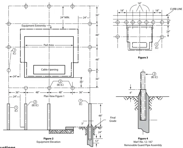
TRAFFIC PROTECTION FOR PAD-MOUNTED TRANSFORMERS
• Transformers shall be protected on all sides exposed to vehicular traffic or within 8' or less from roadways or parking lots.
Installation Instructions
(A) Install guard pipes only when vehicular damage to equipment may occur. Usually 8' or less from roadways or parking lots.
(B) Install removable guard pipe assemblies (Mat’l No. 12-167) in the front of equipment doors only.
(C) Install guard pipe and assembly bases in concrete. Fill stationary guard pipes (Mat’l No. 12-062) with concrete. 2cu.' of concrete is required to set each base.
(D) Position guard pipes and assemblies so that a vehicle will not come in contact with the equipment. See Figure 1 for preferred installation. Figure 3 shows an alternate arrangement where space is limited.
(E) Maintain 36” of clearance in front of equipment doors and 24” of clearance around all sides. All dimensions are minimums and are not to be reduced. This does not apply where the curb line is within 24” of equipment. Figure 3 provides an exception but should only be used when necessary.
Parts and Accessories
Description Material No.
1. Guard Pipe (4” diameter galvanized steel) 12–062 2. Guard Pipe Assembly (4” diameter pipe inside 5” diameter pipe) 12–167
14”
18” 18”
Figure 4
Mat’l No. 12–167 Removable Guard Pipe Assembly
Figure 2
Equipment Elevation
Final Grade Plan View Figure 1
Cable Opening Pad Area Equipment Extremity
CURB LINE 24” MIN. 24”
24” 24” 24” 24” 3” 4” 2 (B) (C) 2 (B) (C) 2 (B) (C) 1 (C) 1 (C) 1 (C) 1 (C) 12” 12” 36” 36” 36” 36” 36” 48” 48” 48” 48” 48” Figure 3
PADmOUNTED EqUIPmENT INFORmATION
2
TRANSFORMER PAD SPECIFICATIONS
• Customers are responsible for purchasing and installing the transformer pads for three-phase transformers. Pre-cast concrete transformer pads can be purchased and delivered to your site from BGE’s Contractor Supplier (See page 28).
• Two different pads are available:
– BGE Material No. 12-668 for use with transformers 500 kVA and smaller.
– BGE Material No. 12-790 for use with transformers 750 kVA and above.
• The dimensions of those pads are shown on page 25. BGE will provide the required pad size for each job. • BGE allows “pour in place” transformer pads, in
accordance with specifications on page 25 and should have two conduits provided for cables in all cases.
Note: A sump may be required under transformers that contain more than 300 gallons of oil (750 kVA or larger). The 40’ diameter sump (to 72” below grade) is required if the final grades will slope towards an adjacent building.
This is especially true if the area around the transformer is to be paved and drains installed. Contact the BGE Representative for the project to determine the final details of design and construction.
• The front of the transformer pad should be placed in such a way as to prevent the crossing of primary and service ducts. This simplifies the installation and maintenance of conduits.
• The pad shall be installed on a level area with a minimum of 8 feet of clear and level operating space in front of the transformer pad. BGE is responsible for the grounding of the transformer pad.
• The customer shall install the ground rod when the pad is installed on the site. If no space is being left in the pad opening, a PVC duct shall be installed to exit the pad side to allow for a grounding connection. • If the duct count exceeds nine, the ducts shall be
banded together within the transformer pad cutout to ensure all ducts remain in their correct spaces within the transformer. (See page 47).
PADmOUNTED EqUIPmENT INFORmATION
TRANSFORMER PAD SPECIFICATIONS
(CONT'D)Flat Pads 12-763, 12-781, 12-668 Flat Pad 12-790
BGE INSTALLS - 12–763 13 KV 1Ø Dead–front transformers (25-167) KVA 12–781 13 KV 1Ø Dead–front transformers (250 KVA)
CUSTOMER - 12–668 13 KV 3Ø Dead–front transformers (75-500) KVA
SUPPLIES and 12–790 13 KV 3Ø Dead–front transformers (750-2500) KVA
INSTALLS *Note: 12-790 has knock outs to increase the size of cable access opening
BGE
BGE
CUSTOMER
CUSTOMER
Material No.
12-763
12-781
12-668
12-790
Substance
Plastic
Fibercrete
Concrete
Concrete
Weight
40#
60#
2200#
4120#
A
42”
48”
78”
100”
B
42”
48”
66”
84”
C
27”
28”
50”
50” - 66”
D
12”
10”
18”
18”
E
8”
10”
14”
17” - 25”
F
6”
6”
6”
8”
G
4”
4”
6”
6”
B E
C G
E Oil Drain
Grooves
Oil Drain Hole D
A
F G
A
8”
8”
C
B
D
*See Note
2
PADmOUNTED EqUIPmENT INFORmATION
BGE PAD-MOUNTED SWITCHGEAR LOCATION REQUIREMENTS
The area surrounding the switchgear shall be level and clear of obstruction. This area shall be level with the top of the switchgear pad and shall extend a minimum of 8' from sides with doors to provide access for stick operations and 4' on other sides.
Planting Details.
Provide opening in shrubbery for replacement of equipment.
Before planting shrubbery or digging anywhere near pad-mounted switchgear, call “Miss Utility” at 811 or 1.800.257.7777
2
PADmOUNTED EqUIPmENT INFORmATION
2
MINIMUM SPACE REQUIREMENTS FOR BGE 13KV
PADmOUNTED EqUIPmENT INFORmATION
MATERIALS AVAILABLE FROM BGE CONTRACTOR SUPPLIER
In order to make materials available and as easy as possible for you to obtain, the following materials are available for purchase through BGE’s Contractor supplier:
• Pad, Precast, Concrete 78 In. X 66 In. • Pad, Precast, Concrete 100 In. X 84 In. • Guard, Pipe 4 Inchs Std Galvanized • Guard, Removable Pipe Assembly • Tape, Marking, 3 In. Wide X 1000 Ft. • Cover, Manhole, 36 Inch
• Frame, 6" Deep, Roadway, Used With 36'' Dia. Cover • Box, Splice, 15 KV
• Box, Splice, 35 KV
• BOX, SPLICING, 600 V, 16''W X 22"L X 30"D
• Enclosure, Below Grade 600 V, 12"W X 12''L X 17''D • Enclosure, Below Grade 600 V, 20''W X 30''L X 16''D • Rod Ground
• Box, Splice 15KV 30'' X 60'' X 36'' Deep • Pad Plastic Flat 42''x42''x4''
• Pad Box 15KV For Pme Air Swgear • Gas Marking Tape
These materials are available by contacting:
Choctaw-Kaul Distribution Company 302-292-2660
edonaghy@choctawkaul.com
Direct on site delivery.
Variety of payment options are available.
All costs are fully disclosed and are subject to change without notice.
3
COmmERCIAL &
INDUsTRIAL
COmmERCIAL & INDUsTRIAL
3
The procedures and specifications in this section apply to Commercial and Industrial projects which include the following:
• New commercial and non-residential building. • Apartments or condominiums.
• Barns or garages on residential or commercial property.
• Service increases to existing commercial or non-residential building. • Traffic signals, CATV power supplies, cell sites or traffic cameras. • Relocation/removal of existing BGE non-residential facilities.
COmmERCIAL & INDUsTRIAL
3
CONDITIONS OF ELECTRIC SUPPLY
Customer electrical loads are to be balanced in such a way that the imbalance between any two phases or legs is less than 10 percent. (Reference BGE Service Tariff sections 9.121 and 9.132. Customer‘s equipment has been significantly damaged by severe load imbalances.)
Electric Service Supply Points
• BGE will supply one service connection:
a. For all the requirements of a single property when the supply is for a group of buildings, the supply point is located, wherever practicable, at a location central to the group. (A central service and meter location is required for flex office and warehouse buildings.)
b. For any separate building of a group, provided such service is for the entire requirements of that building.
c. For any separate building occupied by one or more customers.
• All commercial building structures less than 300 feet long require a single service point for meter installations, except for strip commercial building, which BGE will design on a case-by-case basis. • Where practicable, a single loop will be provided for a
pair of adjoining buildings.
• BGE will supply one meter installation for all
requirements of each customer at each supply point: a. Where two or more customers are supplied from
one service connection, a centralized meter location is required wherever practicable. b. Each meter installation must have a separate
application of the rate schedule.
• BGE provides and considers as “one service connection” and as “one meter installation”:
a. The combination of single-phase and three-phase services.
b. Two or more service connections of the same characteristics where required for a single customer by reason of the size of the load (such as a lighting load in excess of the capacity of one phase distribution) or by reason of the character of the load (such as welders and X-rays where a combination on the same service with lighting is
Note: Totalization of meters may be required. Customer charges apply.
All electric facility installation, lines, and equipment, must conform to the latest edition of the BGE Gas & Electric Metering Manual available under the New Construction Services section on bge.com.
Builder/Developer/Customer
Responsibilities
• Submit your completed Service Application as early as possible in your planning process.
• Provide on premise, without charge, suitable space and supporting structure acceptable to BGE for metering and service equipment. BGE will approve compartments in switchgear to building metering instrument transformers, unmetered service equipment, or cable termination facilities.
• All service equipment other than that specifically stated is furnished, installed, and maintained by you (or the owner), including the service entrance, the service switch or circuit breaker (including the wiring to BGE’s metering equipment where the service switch or circuit breaker is located on the line side of the meter), and any protective equipment required on your distribution system. Where other than a self-contained meter is required, you provide the raceway between BGE’s instrument transformers and the meter.
• Where you elect to furnish and install prefabricated multi-meter socket assemblies, install approved devices. BGE will provide a list of approved devices. Connections will not be made to a device that has not been approved prior to its installation.
• Furnish and install a conduit bank for secondary cable (< 600V) from termination point to transformer pad, concrete-encased if required by BGE.
• Furnish and install a conduit bank for primary cables (> 600V) under paving or improved areas as required by BGE or any city/county regulations, concrete-encased, if required by BGE or any city/county regulations.
• Where applicable, provide suitable meter protection meeting approved BGE specifications at your cost. • Furnish and install pull boxes or manholes for
COmmERCIAL & INDUsTRIAL
3
CONDITIONS OF ELECTRIC SUPPLY
(CONT'D)• Purchase/construct and install transformer pad(s) for three-phase transformers only. (See page 25). • Install warning tape over conduit bank.
• Provide transformer vaults and manholes if required. • Provide certificate of approval from local jurisdiction or
authorized inspection agency to verify conformance. The job will not be released to construction until this is received.
• Baltimore City duct system privilege permits and the associated customer duct construction are the responsibility of the customer. BGE is not an agent. Lack of the proper permit may delay BGE construction.
BGE Responsibilities
• Contact the customer within 10 days of our receipt of the completed Service Application.
• Conduct initial site visit for planning and designing the job.
• Install electric service per extension/relocation contract or gas service sketch.
• Furnish and install the transformers required to step down to secondary distribution system voltage and regulators required on BGE’s distribution system. BGE also furnishes and maintains and, if practicable, installs its meter connection device.
• Furnish and install secondary cables in customer or Baltimore City DPW conduit.
• Terminate and energize all BGE cables.
• Furnish and install all meters after receipt of certificate of approval from the jurisdictional authority for both gas and electric.
• Install BGE’s transformers and appurtenant equipment for general distribution purposes, which normally are located on poles in streets, alleys, and lot lines or on ground level pads adjacent to lot lines, or in manholes or vaults in the street or sidewalk in cable and conduit areas. Where these facilities are necessary solely for your service requirements, they normally are located on your premises.
• Furnish and install single phase transformer pads.
Local Jurisdiction Responsibilities
• Upon application by the licensed electrician, issue the appropriate permit for the installation of customer wiring and equipment, if applicable.
• Inspect and approve customer’s wiring and equipment. • Provide BGE with certificate of approval notification for
customer’s wiring and equipment.
Electrical Service Entrance—
Service at Secondary Distribution
Systems Voltages
• The service switch or circuit breaker must be installed on the load side of the meter, except where the jurisdictional authority requires it to be installed on the line side. Where the installation is on the line side, the service switch or circuit breaker must be so designed that the unmetered wiring is inaccessible without breaking the seal, even during the renewal of switch fuses. Fusible disconnects of the pullout type are acceptable only where specifically approved by BGE. • You must also provide on premise, without charge,
space (including a vault, if required) satisfactory to BGE for the transformers and equipment necessary for your service.
Transformer Vaults
• If BGE requires a vault on premise, you must provide one.
Overhead Electrical Service
Entrance Location
• Service entrances must be located such that the service drop wires and service head are out of reach from doors, windows, porches, and the like.
• Service entrances for adjoining houses must, where practicable, be arranged such that each service drop will supply two houses. Where such houses have an area way between them, the service entrance must be located on the rear wall.
• In the event it becomes necessary to change the service entrance wiring, the service entrance location must conform to these requirements.