Simulation and Application of Maximum Power Tracking
Scheme in a Novel Excitation Synchronous Wind Power
Generator (ESWPG) by using Fuzzy Logic Controller
Golla Sivaramu
M.tech student scholarDepartment of EEE B.I.T.I.T Hindupur Anantapur district mail: [email protected]
E.Nagabhushana
Associate professor Department of EEE B.I.T.I.T Hindupur Anantapur district mail:[email protected]C.Viswanath
Associate professor Department of EEEB.I.T.I.T Hindupur Anantapur district mail:[email protected]
Abstract:- This paper proposes a novel excitation synchronous wind power generator (ESWPG) with a maximum power tracking scheme by using Fuzzy Logic Controller (FLC). The excitation synchronous generator and servo motor rotor speed tracks the grid frequency and phase using the proposed coaxial configuration and phase tracking technologies. The genera-tor output can thus be directly connected to the grid network without an additional power converter. The proposed maximum power tracking scheme governs the exciter current to achieve stable voltage, maximum power tracking, and diminishing servo motor power consumption. The system transient and static responses over a wide range of input wind power are examined using simulated software. MATLAB/ SIMULINK results demonstrate the feasibility of the proposed system.
I. INTRODUCTION
Wind power generators can be divided into induction and synchronous types. The excitation synchronous generator driven by hydraulic, steam turbine, or diesel engines has been extensively adopted in large-scale utility power generation owing to desired features such as high efficiency, reliability, and controllable output power. The global market demand for electrical power produced by renewable energy has steadily increased, explaining the increasing competitiveness of wind power technology [1-6].
A wind power generator in grid connection applications, except for doubly fed induction generators, achieves these features using variable speed constant frequency technology. However, most excitation synchronous wind generators cannot be connected directly to the grid, owing to instabilities in wind power dynamics and unpredictable properties that influence the generator synchronous speed. The direct-drive permanent magnet synchronous wind generator (PMSWG) uses variable speed and power converter technologies to fulfill the grid connection requirements, which has advantages of being gearless.
Various power transfer technologies are applied for ac/dc transformation to obtain a constant frequency ac power [9]–[16]. However, extensive use of power electronic devices in those systems that will cause unavoidable power losses from the rectifier‟s conducting resistance and high-frequency power switches, which will increase power consumption. Therefore, a converterless method for a high-efficiency excitation synchronous wind generator is an important issue, especially for middle and high output voltage wind power generators. This paper presents a novel converterless wind power generator with a control framework that consists of an excitation synchronous generator, permanent magnet (PM) synchronous servo motor, signal sensors, and servo control system and maximum power tracking scheme by using Fuzzy Logic Controller (FLC).
II. POWER FLOW AND SPEED OF PROPOSED SYSTEM
Fig. 1. Power flow block diagram
Fig. 1 shows the power flows of the proposed system, where Tw, Tm and Tg denote the torques and Ww, Wm, and Wg are the wind turbine, servo motor, and excitation synchronous generator speeds, respectively. For simplicity, assume that all energy transmission elements behave ideally, allowing us to ignore the mechanical power losses of the wind turbine, the servo motor, and the excitation synchronous generator. The total excitation synchronous generator input power is the product of Tg and Wg. The power flow equation can thus be defined as
Fig. 2. Proposed coaxial construction configuration
Fig. 2 shows the corresponding coaxial configuration. The wind generator rotor shaft input-end receives rotating torques from the speed increasing gear box. The tail-end of the generator rotor shaft is coupled with a servo motor. The input energy of the excitation synchronous generator is the sum of the wind power and servo motor powers. The speed and rotating direction for the wind turbine output, servo motor, and excitation synchronous generator is the same, i.e., the system speeds satisfy Ww=Wm=Wg. This arrangement can reduce the power transmission losses.
III. CONTROL PRINCIPLES OF PROPOSED WIND POWER GENERATOR SYSTEM
The control system design concepts maintain power flow balance between the input and the output and, simultaneously, force the generator frequency to synchronize with the utility grid. Fig. 3 depicts the control framework of the proposed system. When the system complies with these conditions, the generator output can be connected to the utility grid network,
subsequently reaching the high efficiency and maximum power tracking objectives. The control signals, including the generator voltage, current, grid phase, motor encoder, and output power, are sensed and transferred to the microprocessor control unit (MCU).
Fig. 3. Proposed wind power system framework
The servo motor controller plays an important role in output power and grid voltage phase tracking. A situation in which the controller detects a power increase from the servo motor implies decreasing wind speeds. At this moment, the system regulates the exciter current to reduce the excitation generator output power. A chain reaction subsequently occurs in which the servo motor power returns to a balanced level. During the energy balance periods, the servo motor consumes only a slight amount of energy to stabilize the shaft speed. Once (1) is satisfied, both the maximum power and the constant speed can be obtained by the designed control scheme.
Fig. 4. Proposed wind power generator system
measures the motor output power as the reference signals to determine the generator output power.
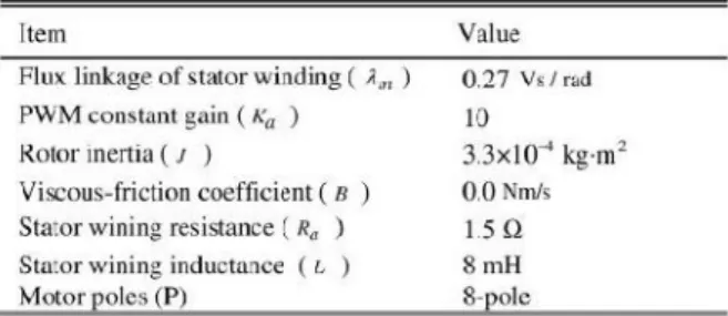
TABLE I
PARAMETERS OF PM SYNCHRONOUS MOTOR
The excitation synchronous generator output frequency, voltage-phase, and output power are fed back into the control scheme. The phase/frequency synchronization strategy in Fig. 4 compares the grid voltage-phase and frequency with the generator‟s feedback signals, and produces the position command with pulse-type signals to the servo motor driver. The MPTC also adjusts the excitation field current based on the wind power and motor power inputs, where øm denotes the servo motor rotor mechanical rotor angular displacement detected by an encoder. Due to the coaxial configuration, detecting the relative position of the rotor allows us to determine the generator voltage phase during the wind power generator system operating in the grid connection state. The following sections detail the system sub-blocks configuration.
IV. SERVO MOTOR CONTROLLER DESIGN
The transient and dynamic responses of the servo motor controller must satisfy robustness requirements to reduce the influence of wind fluctuations to the generator. Thus, the robust integral structure control (RISC) method is chosen to ensure the voltage phase and the frequency in phase with the grid. Among general electrical motors, the three-phase PM synchronous motor has the advantages of high-efficiency and low-maintenance requirements, the reason controllable power for the servo control structure was chosen in the research [17]–[20]. This study de-signs an analysis model based on the electrical circuit, motor torque, and mechanical theorems.
Fig. 5. PM synchronous motor block diagram
Fig. 5 shows the block diagram of the three-phase PM synchronous motor, and Table I lists the parameters of the PM synchronous motor. According to (1), wind power, generator power, and servo motor power can be transformed into three torque functions and incorporated in the three-phase PM synchronous motor model.
The electromagnetic torque of the servo motor can be expressed as
The mechanical torque Tm can be expressed as
In Fig. 5, denotes the inductance of the stator windings; represents the amplitude of the flux linkage established by the permanent magnet as viewed from the stator windings; It is clear from the physical characteristics stated above that the motor electrical time constant is overwhelmingly lower than the mechanical time constant as . The three-phase PM synchronous motor model can thus be simplified as a first-order mathematical model, as shown in Fig. 6.
According to Fig. 6, the position control structure includes the RISC and servo motor transfer function. The conventional motor current feedback controller can avoid instantaneous current stress to the servo driver. This technology has been applied to the servo motor control to improve the control performance. The RISC outer loop is designed to achieve a fast and accurate servo tracking response under load disturbances and plant parameter variations.
The PM synchronous motor state equations are described as
RISC is a typical state feedback control scheme that combines an integral controller and the plant series state feedback information. For a third RISC system, the control function U can be expressed as follows:
Transfer function of the system is
By designing the system characteristic function to lie on the stable plane, one can obtain
The characteristic function of (7) can then be rewritten as
The system control gain K1, K2, and K3 can be determined by (9) and the pole-zero placement method
V. PHASE TRACKING CONTROL SCHEME Fig. 7 depicts the proposed phase tracking control scheme. Before the excitation synchronous generator system connects to the grid (SW=0), θ*equals to the grid voltage angle. With the coaxial configuration described in Section II, the servo motor and generator electrical angle can be obtained using the motor encoder and the grid voltage sensor, respectively. The MCU compares the phase difference between the two signals,
and gradually adjusts the excitation synchronous generator rotor position to reduce the phase deviation.
Fig. 7. Phase tracking control scheme
Fig. 7 reveals that, while the proposed system contains a phase deviation, the deviation frequency can be expressed as follows:
The MCU generates pulse trains of frequency command for the servo motor to drive the servo motor, explaining why the generator can lock the generator frequency and phase in the phase command. When the generator is connected to the grid (SW=1), θ* equals the generator current angle. MCU calculates the generator electrical angle and current phase angle difference to adjust the generator rotor position to reduce the phase deviation. Consequently, the generator power factor can be controlled and improved.
VI. MAXIMUM POWER TRACKING CONTROL METHOD
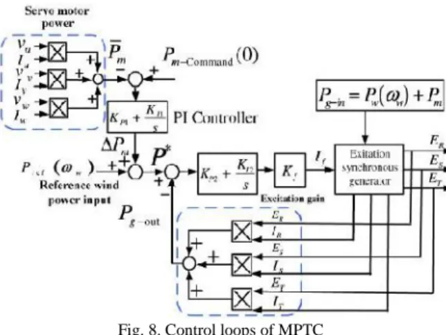
In a natural environment, the wind power varies with time. To stabilize the generator output voltage, current, and output power, the excitation synchronous generator output power has to track the input power variation and react immediately by adjusting the excitation field current. In this paper, a maximum power tracking control scheme is proposed. The proposed MPTC scheme includes two control loops as shown in Fig. 8, which is motor power control loop, and the generator power control loop. By MPTC scheme, it can make the motor consumption power minimize and most of wind power can be transferred to the grid by the generator. The control strategy describes as follows.
Fig. 8. Control loops of MPTC
If an air dynamic occurs in the wind turbine, the servo motor responses to this change for maintaining generator speed constant.
As is expected, in the steady state, the servo motor consumes less power. One defines the generator power command P* as follows:
VII. MODEL OF THREE-PHASE EXCITATION SYNCHRONOUS GENERATOR
For a typical three phases, four poles excitation synchronous generator, the generator output power is governed by the excitation controller, through the slip rings, with the appropriate excitation current sent to the armature winding. Based on the rotating magnetic field affection, the stator windings induce three-phase alternate voltages which have frequency in synchronization with the rotor speed [21], [22]. According to the conductor‟s electromagnetism and the mechanical forces on the stator winding and rotor, the generator back electromotive force voltage can be defined as
where E denotes the back electromotive force voltage of the excitation synchronous generator stator; l represents the conductance magnet effective length; wg is the rotor speed; and B is the magnetic field strength. The magnetic field strength B can also be rewritten as
Combining (14) and (15) yields
Fig. 9. Excitation synchronous generator model
The excitation synchronous generator outputs for each back electromotive force voltage are described as follows
Fig. 9 shows a block diagram of the three-phase excitation synchronous generator between the excitation input current and the generator output according to (15)–(20).
VIII. FUZZY LOGIC CONTROL
In FLC, basic control action is determined by a set of linguistic rules. These rules are determined by the system. Since the numerical variables are converted into linguistic variables, mathematical modeling of the system is not required in FC. The FLC comprises of three parts: fuzzification, interference engine and defuzzification. The FC is characterized as; i. Seven fuzzy sets for each input and output. ii. Triangular membership functions for simplicity. iii. Fuzzification using continuous universe of discourse. iv. Implication using Mamdani‟s „min‟ operator. v. Defuzzification using the „height‟ method.
Fig.10 Fuzzy Logic Controller Fuzzification
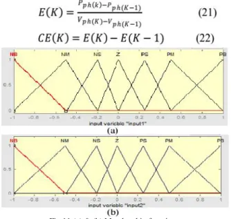
Membership function values are assigned to the linguistic variables, using seven fuzzy subsets: NB (Negative Big),NM(Negative Medium), NS (Negative Small), ZE (Zero), PS (Positive Small),PM(Positive Medium) and PB (Positive Big). The partition of fuzzy subsets and the shape of membership function adapt the shape up to appropriate system. The value of input error E(k) and change in error CE(k) are normalized by an input scaling factor [11] and [12].
Fig.11 (a) & (b) Membership functions
Inference Method
Several composition methods such as Max– Min and Max-Dot have been proposed in the literature. In this paper Min method is used. The output membership function of each rule is given by the minimum operator and maximum operator. Table II shows rule base of the FLC.
Defuzzification
As a plant usually requires a non-fuzzy value of control, a defuzzification stage is needed. To compute the output of the FLC, „height‟ method is used and the FLC output modifies the control output. Further, the output of FLC controls the switch in the inverter.. In order to control these parameters, they are sensed and compared with the reference values. To achieve this, the membership functions of FC are: error, change in error as shown in Figs. 11(a), (b). In the present work, for fuzzification, non-uniform fuzzifier has been used. If the exact values of error and change in error are small, they are divided conversely and if the values are large, they are divided coarsely.
Where α is self-adjustable factor which can regulate the whole operation. E is the error of the system, C is the change in error and u is the control variable.
A large value of error E indicates that given system is not in the balanced state. If the system is unbalanced, the controller should enlarge its control variables to balance the system as early as possible. One the other hand, small value of the error E indicates that the system is near to balanced state. Overshoot plays an important role in the system stability. Less over shoot is required for system stability and in restraining oscillations. C in (12)
plays an important role, while the role of E is diminished. The optimization is done by α. The set of FC rules is given in Table II.
TABLE II FUZZY RULES
IX. SIMULATION RESULTS
This paper proposes a novel excitation synchronous wind power generator (ESWPG) with a maximum power tracking scheme by using Fuzzy Logic Controller (FLC). Simulation results obtained by MATLAB/ SIMULINK are presented, and the performance of the proposed scheme is analyzed. The generator design functionality is confirmed using a wind power generator framework simulation model with an excitation synchronous generator and its corresponding sub-systems, using MATLAB/ SIMULINK software. Sub-systems include the wind power input, servo motor phase tracking control, maximum power tracking control, excitation synchronous generator, and grid connection. Tables I and III list the parameters of the PM synchronous motor, excitation synchronous generator, respectively. To output the three-phase voltage signals at 50 Hz, the excitation synchronous generator must operate at 1800 rpm with 4-pole windings.
TABLE III
Fig. 12. Simulation results. (a) Phase voltage and current of the excitation synchronous generator. (b)
Voltage phase tracking.
The voltage phase tracking performance of the system at generator output 2 kW is investigated. Fig. 12(a) shows the phase voltage and current waveforms of the excitation synchronous generator. Fig. 12(b) shows the grid and generator voltage phase tracking waveforms. The simulation voltage and current waveforms in Fig. 12(a) confirm that the proposed system has high-quality power and sufficient control stability during grid connection. The generator output phase voltage is in phase with the grid in Fig. 12(b). Owing to the excitation synchronous generator rotation speed control and excitation control, the output power, voltage, and frequency are constant. The wind power generator system can thus connect directly to the grid.
Fig. 13. Maximum power tracking simulation results. (a) Power tracking curves. (b) Generator input torque.
(c) Shaft speed. (d) Shaft acceleration.
For evaluating the system performance under grid connection, input wind with step changes were applied. In the beginning, 13 s of the simulation, a stable 2-kW wind power input is provided as shown in Fig. 13(a). At the 13th second, a step wind disturbance with 2±0.5kW amplitude was suddenly added to observe the power tracking condition. According to the simulation wave-forms, the excitation synchronous generator output power was around 1.9 kW for 0–13 s. Thereafter, the wind power system tracked the input wind disturbance using the proposed maximum power tracking method.
X. CONCLUSION
In the proposed framework, the servo motor provides controllable power to regulate the rotor speed and voltage phase under wind disturbance. This paper presented an excitation synchronous wind power generator with MPTC scheme by using Fuzzy Logic Controller (FLC). Using a phase tracking control strategy, the proposed system can achieve smaller voltage phase deviations in the excitation synchronous generator. In addition, the maximum output power tracking scheme governs the input and output powers to achieve high performance. The excitation synchronous generator and control function models were designed from the physical perspective to examine the presented functions in the proposed framework. FLC based simulation results demonstrate that the proposed wind power generator system achieves high performance power generation with salient power quality with efficient performance.
REFERENCES
[1] M. Liserre, R. Cárdenas, M. Molinas, and J. Rodriguez, “Overview of Multi-MW wind turbines and wind parks,” IEEE Trans. Ind.Electron., vol. 58, no. 4, pp. 1081–1095, Apr. 2011.
[2] V. Delli Colli, F. Marignetti, and C. Attaianese, “Analytical and multi-physics approach to the optimal design of a 10-MW DFIG for directdrive wind turbines,” IEEE Trans. Ind. Electron.,vol. 59, no. 7, pp. 2791–2799, Jul. 2012.
[3] B. Singh and S. Sharma, “Design and implementation of four-leg voltage-sourceconverter-based VFC for autonomous wind energy conversion system,” IEEE Trans. Ind.Electron., vol. 59, no. 12, pp. 4694–4703, Dec. 2012.
[4] A. Di Gerlando, G. Foglia, M. F. Iacchetti, and R. Perini, “Axial flux pm machines with concentrated armature windings: Design analysis and test validation of wind energy generators,”IEEE Trans. Ind. Electron., vol. 58, no. 9, pp. 3795–3805, Sep. 2011.
[5] S. Zhang, K.-J. Tseng, D. M. Vilathgamuwa, T. D. Nguyen, and X.-Y. Wang, “Design of a robust grid interface system for PMSG-based wind turbine generators,” IEEE Trans. Ind. Electron.,vol. 58, no. 1, pp. 316–328, Jan. 2011.
[6] F. Bu, W. Huang, Y. Hu, and K. Shi, “An excitation-capacitor-optimized dual statorwinding induction generator with the static excitation controller for wind power application,” IEEE Trans. Energy Convers., vol. 26, no. 1, 122–131, Mar. 2011.
[7]S. Le-peng, T. De-dong, W. Debiao, and L. Hui “Simulation for strategy of maximal wind energy capture of doubly fed induction generators,” in Proc. IEEE Int. Conf. Cognit. Informat., Jul. 2010, pp. 869– 873.
[8]W. Qi, C. Xiao-hu, F. Wan-min, and J. Yanchao, “Study of brushless doubly-fed control for VSCF wind
power generation system connected to grid,” in Proc. Int. Conf. Electr. Utility Deregulation Restruct. Power Technol., Apr. 2008, pp. 2453–2458.
[9]A. Mesemanolis, C. Mademlis, and I. Kioskeridis, “Maximum efficiency of a wind energy conversion system with a PM synchronous generator,” in Proc. IEEE Int. Conf. Exhib. Power Gener. Transm. Distrib. Energy Convers., Ayia Napa, Cyprus, Nov. 2010, pp. 1–9.
[10] H. Geng, D. Xu, B. Wu, and G. Yang, “Active damping for PMSG-based WECS with DC-link current estimation,” IEEE Trans. Ind. Electron., vol. 58, no. 4, pp. 1110–1119, Apr. 2011.
[11] W.-M. Lin and C.-M. Hong, “A new Elmanneural network-based control algorithm for adjustable-pitch variable-speed wind-energyconversion systems,” IEEE Trans. Power Electron., vol. 26, no. 2, pp. 473–481, Feb. 2011.
[12] C. Xia, Q. Geng, X. Gu, T. Shi, and Z. Song, “Input–output feedback linearization, and speed control of a surface permanent-magnet synchronous wind generator with the boostchopper converter,” IEEE Trans. Ind. Electron., vol. 59, no. 9, pp. 3489–3500, Sep. 2012.
[13] J. H. Zhao, F. Wen, Z. Y. Dong, Y. Xue, and K. P. Wong, “Optimal dispatchof electric vehicles, and wind power using enhanced particle swarm optimization,” IEEE Trans. Ind. Inf., vol. 8, no. 4, pp. 889–899, Nov. 2012.
[14] S. Alepuz, A. Calle, S. Busquets-Monge, S. Kouro, and B. Wu, “Use of stored energy inPMSG rotor inertia for low-voltage ride-through in back-to-back npc converter-based wind powersystems,” IEEE Trans. Ind. Elec-tron., vol. 60, no. 5, pp. 1787–1796, Sep. 2013. [15] C. Xia, Q. Geng, X. Gu, T. Shi, and Z. Song, “Input–output feedback linearization, and speed control of a surface permanent-magnet synchronous wind generator with the BoostChopper converter,” IEEE Trans. Ind. Electron., vol. 59, no. 9, pp. 3489–3500, Sep. 2012.
[16] A. G. Abo-Khalil, D.-C. Lee, and S.-H. Lee,“Grid connection of doubly-fed induction generators in wind energy conversion system,” in Proc. IEEE Int. Conf. Power Electron. Motion Control, Aug. 2006, vol. 3, pp. 1–5.
[17] T.-L. Chern et al.,“Digital signalprocessing-based sensor-less permanent magnet synchronous motor driver with quasi-sine pulsewidth modulation for air-conditioner rotary compressor,” IET Electr. Power Appl., vol. 6, no. 6, pp. 302–309, Sep. 2012.
[18] G. K. Chang, T. L. Chern, and D. M. Tsay, “Globoidal cam indexing servo drive control by IVSMFC with load torque estimator,” Trans.Ind. Appl., vol. 38, no. 5, pp. 1326–1333, Sep. 2002.
GOLLA SIVARAMU A currently pursuing her M.Tech in Electrical Power Systems in B.I.T institute of Technology,Hindupur,Andra pradesh, India affiliated to JNTU University, Anantapur. He has done her B-Tech degree from Krishna chaitanya institute of Technology and Sciences, affiliated to JNT University,Kakinada,Andrea Pradesh, India.
E.NAGABHUSHANA presently working as Associate professor in B.I.T institute of Technology , Hindupur, Andra pradesh, India. Completed his M.Tech in Energy Systems from JNTU-A University, Anantapur and B.tech from SITAMS college of engineering , Chittoor. His fields of interest include Non Conventional Energy Sources, Advanced Control Techniques in Power Systems and electrical machines.