Structural and Thermal Analysis of Disc Brake With and Without
Cross Drilled Rotor
1
Vijay Dadi,2Koteswara Rao K,3J Hari Narayana Rao 1M. Tech. Student,2Asst. Professor,
Dept of Me, KITS , Divili. 3Research Scholar
Abstract:- The disc brake is a device for slowing or
stopping the rotation of a wheel. A brake disc (or rotor), usually made of cast iron or ceramic composites (including carbon, Kevlar and silica), is connected to the wheel and/or the axle. To stop the wheel, friction material in the form of brake pads (mounted on a device called a brake caliper) is forced mechanically, hydraulically, pneumatically or electromagnetically against both sides of the disc. Friction causes the disc and attached wheel to slow or stop. Brakes convert friction to heat, but if the brakes get too hot, they will cease to work because they cannot dissipate enough heat. This condition of failure is known as brake fade. Disc brakes are exposed to large thermal stresses during routine braking and extraordinary thermal stresses during hard braking. The aim of the project is to model a disc brake used. Coupled field analysis (Structural + Thermal) is done on the disc brake. The materials used are Cast Iron, stainless steel and aluminum alloy. Analysis is also done by changing the design of disc brake. Actual disc brake has no holes, design is changed by giving holes in the disc brake for more heat dissipation. Modeling is done in Pro/Engineer and analysis is done in Ansys.
I. INTRODUCTION
The disc brake is a device for slowing or stopping the rotation of a wheel. A brake disc (or rotor) usually made of cast iron or ceramic composites (including carbon, Kevlar and silica), is connected to the wheel and/or the axle. To stop the wheel, friction material in the form of brake pads (mounted on a device called a brake caliper) is forced mechanically, hydraulically, pneumatically or electromagnetically against both sides of the disc. Friction causes the disc and attached wheel to slow or
wheels, and some have disc brakes on all four wheels. This is the part of the brake system that does
the actual work of stopping the car. In today’s
growing automotive market the competition for better performance vehicle in growing enormously. The racing fans involved will surely know the importance of a good brake system not only for safety but also for staying competitive As we are aware of the fact that races are won over split of a second.
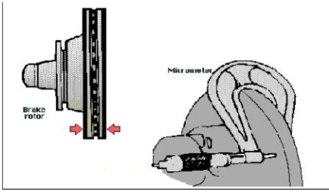
2. BRAKE ROTOR
2.1 ROTOR SPECIFICATIONS:
A. Hardness: It is a direct correlation to wear characteristics. Friction materials can be very aggressive and achieve high temperatures. Run out: In order to ensure no free running drag, when
mounted on a hub rotors must not have any “wobble”
that would take up any pad clearance and drag on the pads.C. Thickness Variation: It must be kept to a minimum. Thickness differences in the rotor can cause pulsing in both the vehicle and the lever as thicker and thinner sections pass through the caliper pads.
2.2 RUB AREA DESIGN:
The rub area of a rotor must be designed carefully. The rub area must provide adequate surface area to support the brake pads while braking. They must also have the proper cutouts to provide pad cleaning during braking. Finally, burnish, power, heat and noise issues are also considered when designing a rub area pattern.
send rotor temperatures soaring into the 600, 700 or even 800 degree range.
Fig 2.1 Rotor thickness variation
If rotor temperatures keep going up because the driver is riding the brakes (as when traveling down a steep mountain) or is driving aggressively, the brakes may get so hot they start to fade. Once this occurs, it takes more and more pedal effort to slow the vehicle.
2.3 ROTOR DESIGN
Rotors are made of cast iron for three reasons
1.It is relatively hard and resists wear. 2.It is cheaper than steel or aluminum.
3.It absorbs and dissipates heat well to cool the brakes.
3.INTRODUCTION TO PRO-ENGINEER
Pro-ENGINEER Wildfire is the standard in 3D product design, featuring industry-leading productivity tools that promote best practices in design while ensuring compliance with industry and company standards. Integrated Pro-Engineer / CAD/CAM/CAE solutions allow to design faster than ever, while maximizing innovation and quality to ultimately create exceptional products.
Customer requirements may change and time pressures may continue to mount, but product design needs remain the same - regardless of project's scope, need the powerful, easy-to-use, affordable solution that Pro-ENGINEER provides.
3.1 PRO-ENGINEER WILDFIRE BENEFITS
•Unsurpassed geometry creation capabilities
allow superior product differentiation and manufacturability
•Fully integrated applications allow us to develop everything from concept to manufacturing within one application
•Automatic propagation of design changes
to all downstream deliverables allows you to design with confidence
•Complete virtual simulation capabilities
enable to improve product performance and exceed product quality goals
•Automated generation of associative
tooling design, assembly instructions, and machine code allow for maximum production efficiency
Pro-ENGINEER can be packaged in different versions to suit our needs, from Pro-ENGINEER Foundation XE, to Advanced XE Package and Enterprise XE Package, Pro-ENGINEER Foundation XE Package brings together a broad base of functionality. From robust part modeling to advanced surfacing, powerful assembly modeling and simulation, our needs will be met with this scaleable solution. Flex3C and Flex Advantage Build on this base offering extended functionality of choosing.
3.2 DIFFERENT MODULES IN PRO-ENGINEER
PART DESIGN ASSEMBLY DRAWING SHEETMETAL
By using the Pro-Engineer software was designed the 3D model of solid and ventilated disc
rotors because compared to the other 3D software’s
Pro-Engineer is easy to draw.
The Fig 3.1 shows the design of solid disc rotor. It is designed by using the above calculated design data and Pro-E software. In this fig. shows the wheel hub holes with 12mm diameter.
Fig 3.2 Disc Brake With Holes
The above fig 3.2 shows the design of a ventilated disc rotor. It is designed By Using Pro-E. For solid disc I have provided holes with 8mm diameter.
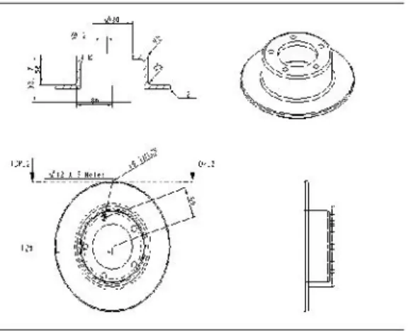
Fig: 3.3 Draft model of a solid disc
The above figure 3.3 shows the Draft Model of a solid disc rotor in different views i.e. front view, top view and side view.
The below figure 3.4 shows the Draft Model of a ventilated disc rotor in different views i.e. front view, top view and side view.
Fig: 3.4 Draft model of a ventilated disc
4. INTRODUCTION TO ANSYS
ANSYS is general-purpose finite element analysis (FEA) software package. Finite Element Analysis is a numerical method of deconstructing a complex system into very small pieces (of user-designated size) called elements. The software implements equations that govern the behaviour of these elements and solves them all; creating a comprehensive explanation of how the system acts as a whole. These results then can be presented in tabulated, or graphical forms. This type of analysis is typically used for the design and optimization of a system far too complex to analyze by hand. Systems that may fit into this category are too complex due to their geometry, scale, or governing equations.
ANSYS is the standard FEA teaching tool within the Mechanical Engineering Department at many colleges. ANSYS is also used in Civil and Electrical Engineering, as well as the Physics and Chemistry departments.
ANSYS provides a cost-effective way to explore the performance of products or processes in a virtual environment. This type of product development is termed virtual prototyping.
4.1 STEPS INVOLVED IN ANSYS
dimensionality of the analysis (i.e. 1D, 2D, axis, symmetric)
2. Solution processor module: assigning the loads ,constraints and solving. Here we specify the loads (point or pressure), constraints (translation, rotational) and finally solve the resulting set of equations.
5.2 TYPES OF STRUCTURAL ANALYSIS
StaticAnalysis--Used to determine displacements, stresses, etc. under static loading conditions. Both linear and nonlinear static analyses. Nonlinearities can include plasticity, stress stiffening, large deflection, large strain, hyperelasticity, contact surfaces, and creep.
Modal Analysis--Used to calculate the natural frequencies and mode shapes of a structure. Different mode extraction methods are available.
Harmonic Analysis--Used to determine the response of a structure to harmonically time-varying loads.
Transient Dynamic Analysis--Used to determine the response of a structure to arbitrarily time-varying loads. All nonlinearities mentioned under Static Analysis above are allowed.
Spectrum Analysis--An extension of the modal analysis, used to calculate stresses and strains due to a response spectrum or a PSD input (random vibrations).
Buckling Analysis--Used to calculate the buckling loads and determine the buckling mode shape. Both linear (eigenvalue) buckling and nonlinear buckling analyses are possible.
Explicit Dynamic Analysis--This type of structural analysis is only available in the ANSYS LS-DYNA program. ANSYS LS-DYNA provides an interface to the LS-DYNA explicit finite element program. Explicit dynamic analysis is used to calculate fast solutions for large deformation dynamics and complex contact problems.
In addition to the above analysis types, several special-purpose features are available:
Fracture mechanics Composites Fatigue p-Method Beam Analyses
By using the ansys software was analyzed the structural and thermal analysis of solid and ventilated disc for three different type of materials
named as stainless steel, cast iron and aluminum alloy.
6. RESULTS ANALYSIS
6.1 STRUCTURAL ANALYSIS OF BRAKE DISC WITHOUT CROSS DRILLED HOLES
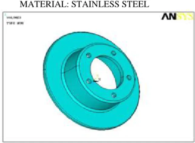
MATERIAL: STAINLESS STEEL
Fig: 6.1 SOLID MODEL OF A BRAKE DISC
The above fig 6.1 shows solid disc rotor model imported from the Pro-E software to the LS DYNA ansys software
MATERIAL: CAST IRON
Element Type: Solid 20 node 95
Material Properties: Youngs Modulus (EX) : 103000 N Poissons Ratio (PRXY) : 0.211
Density:0.0000071 Kg/mm3
The above fig 6.2 shows the displacement analysis of a solid disc rotor for cast iron material. It can withstand maximum displacement of 0.670E-03
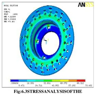
Fig:6.3STRESSANALYSISOFTHE VENTILATED DISC
MATERIAL: ALUMINIUM ALLOY
Element Type: Solid 20 node 95
Material Properties: Youngs Modulus (EX) : 70
Poissons Ratio (PRXY) : 0.33
Density :0.0000028 Kg/mm3
Fig: 6.4 DISPLACEMENT ANALYSIS OF THE VENTILATED DISC
Fig: 6.5 THERMAL FLUX ANALYSIS OF THE VENTILATED DISC
CONCLUSION
This project presents the performance advantages that cross drilled rotor can offer in automotive disc brake applications because ventilated disc offer more heat transfer and less weight.
The design shows the various modifications that can be done in rotor to help them create more friction disperse more heat more quickly, ventilate gas weight reductions.
The heat dissipation during the braking is improved due to direct exposure to atmosphere. The pad wears in a uniform rate. Thus the design of brake system is studied and some model calculations of disc brake and analysis of solid and ventilated rotor for three different material have been done and also comparison of solid and ventilated disc rotor for three materials have been done.
The types of materials used for design process are stainless steel, cast iron and aluminium alloy.
According to the displacement analysis, the aluminiumventilated disc has more displacement when compared to solid disc of same material differed by a value of 0.26012.
After observing the stress analysis results, the steel ventilated disc withstands to more stress when compared to solid disc of same type differed by a value of 134.036 N/mm2.
disc is 187K lesser o the temperature produced in solid disc of same type.
Thermal gradient analysis depicts that the aluminium ventilated disc has 185.023 K/mm as the value and the solid disc of the same type has 18.192 K/mmas the value.
Thermal flux analysis shows the aluminium ventilated is giving more heat dissipation per unit area compared to solid disc of same type.
The results mentioned above are considered for the material of best.
Considering the above aluminium ventilated disc is best suited for the given range of application.
REFERENCES
[1]Mirza Grebovic, “Investigation of the Effects on Braking Performance of Different Brake Rotor
Designs”.
[2] Limpert, Rudolf “Brake Design and Safety”,
Society of Automotive Engineers., Inc, PA, USA, 1992
[3] Warren Chan, “Analysis of Heat Dissipation in
Mechanical Braking Systems”.
[4] David A. Johnson, Bryan A. Sperandei, et.al.,
“Analysis of the Flow Through a Vented Automotive Brake Rotor
[5]David Antanaitis and Anthony Rifici, “The Effect of Rotor Crossdrilling on Brake Performance”. SAE
2006-01-0691
[6] Brake Design and Safety, 2nd Ed., Rudolf Limpert, 2007.
[7] Dr. N.K. Giri, Automobile Mechanics, Khanna publishers, 2009.
[8] James D. Halderman, Automotive Braking System, 2005.
[9] Dr.Kirpal Singh, Automobile Engineering, Volume1,Standard Publishers Distributors, 2007
[11] http://www.stoptech.com
[12] http://www.brakeinfo.com
VIJAY DADI currently pursuing his M.Tech in Thermal Engineering in Kakinada Institute of Technology and Sciences, Divili, Andra pradesh, India affiliated to JNTUK University.He has done his B-Tech degree from Siddartha Engineering collage, affiliated to Nagarjuna University, , Andhra pradesh, India and His fields of interest include Renewable Energy Sources, ic engines.
KOTESWARA RAO K presently working as Assistant professor Engineering in Kakinada Institute of Technology and Sciences, Divili, Andra pradesh India. Completed his. M.Tech in from JNTU-kUniversity, Kakinada and B.Tech from svvsn engineering College, ongole. His fields of interest include Non Conventional Energy Sources, Advanced optimization Techniques and production technology.
J HARI NARAYANA RAO Research