Modeling and Thermal Conduction and Static Analysis of an IC Engine
Piston using CATIA V5 Tool and ANSYS
Sangeetham Sivakumar#1, Guru Murthy N#2, P.Satish Reddy#3 Scholar of Master of Technology, Asst Professor, Assoc Professor
Dept of Mechanical Engineering, Prasiddha College of Engg & Tech, Anathavaram [email protected],[email protected],[email protected]
Abstract:
In now a days technology, diesel engine plays an important role in the transportation sector, agriculture pumping sets etc, where large amount of diesel consumed. But according to the ministry of petroleum, the petroleum fuels will last in few years. So, one must concentrate much on the diesel engine modifications so that the amount of fuel consumption and the environmental pollutions can be reduced. The temperature distribution in the piston is a crucial parameter which influences the thermal stress and deformations in the piston materials. So in the present work I tried thermal conductivity and static analysis on cast iron, aluminium and brass materials based pistons. Keywords: Piston, catiaV5, ANSYS, brass, aluminium, cast iron, analysis
I. Introduction
Piston is a most important component of an internal combustion engine. Its working condition is very important to calculate the piston temperature distribution in order to control the thermal stresses and deformation. In the working condition of piston produce the thermal stress and deformation due to periodic combustion and load effect which produce from high gas pressure, high speed reciprocating motion. By the burning of the fuels the high temperature and pressure generates on piston head which make the piston expand which creates thermal stress and thermal deformation. The thermal deformation and mechanical deformation causes piston cracks, tortuosity etc. Therefore it is very essential to check out or analyze the stress distribution, temperature distribution, heat transfer, thermal load, mechanical load in order to minimize the thermal stress and different thermal loads on working condition of the piston. Most of the internal combustion engine piston is made of Aluminium alloy, forged cast iron and brass and forged steels. So different materials have different thermal conductive properties because of its density. Therefore it is very necessary to examine the crucial thermal
conduction behavior of the piston with different materials. In this study firstly make the virtual piston on real working environment by the modeling software catiav5 and finally analysis the piston with deferent material properties like cast iron, aluminium alloy, and brass giving boundary constraints by ANSYS.
The present work has been based on the following objectives
1. To design an IC engine piston using catiav5.
2. To perform the structural and thermal analysis of piston using ANSYS 10.0. Classic
II. Piston
It is considered as the heart of the I.C engine. Its main function is to transmit the force exerted by the burning of charge to the connecting rod, to form a seal so that the high pressure gases in the combustion chamber do not scope into the crankcase, to serve as guide and a bearing for small end of the connecting rod.
The piston must have some other desirable characteristics
1. It should be silent in operation both during warming up and the normal running.
2. The design should be such that the seizure does not occur.
3. It should offer sufficient resistance to corrosion due to some products of combustion ex sulphur dioxide. 4. It should have the shortest possible length so as to decrease overall engine size.
5. It should be lighter in weight so that inertia forces created by its reciprocating motion are minimum
6. It material should have a high thermal conductivity for efficient heat transfer so that higher compression ratios may be used without the occurrence of detonation. 7. It must have long life
III. Piston Materials
the reciprocating part. There are some drawbacks of Aluminium alloys in comparison to brass and cast iron that are the Aluminium alloys are less in strength and in wearing qualities. The heat conductivity property of Aluminium is about of thrice of the cast iron, Twice of the brass Aluminium pistons are made thicker which is necessary to give proper cooling and it have higher strength at higher temperatures.
S.N O
MATERI AL
THERMAL CONDUCTI VITY (W/m-C)
DENS ITY (KG/m
3)
SPECI FIC HEAT (KJ/K G-C) 1. BRASS 119 8.8E+3 0.380
2. CAST IRON
55 7.92E+
3
0.456
3. ALUMIN IUM
143 2.8E+3 0.795
IV. Design consideration for a Piston
S.no Parameters Values 1 Stroke (L) 106mm
2 Bore(D) 79.62mm 3 Permissible bending
stresses at piston head
(σb)
50 to 90 N/mm2
4 Thickness of piston head according to
Grashoff’s formula (th)
14mm
5 Thickness of piston head on the basis of Heat dissipation aluminium
1.1mm
6 Thickness of piston head on the basis of Heat dissipation cast iron
3.2mm
7 Thickness of piston head on the basis of Heat dissipation brass
1.4mm
Piston Design formulae for calculations
The thickness of the piston head, according to Grashoff’s
formula is given by
th=√((3 x p x D2) / 16 x σt),
p = Maximum gas pressure in N/mm2, D = cylinder bore diameter.
σt= Permissible bending stresses, 30 to 90 N/mm 2
Thickness of piston head on the basis of Heat dissipation tH= H / (12.56 x k (Tc - Te)
H = heat flowing through the piston head in kJ/sec, k = heat conductivity factor W/moc.
Tc = temperature at the center on the piston head inoc, Te = temperature at the edge on the piston head inoc. The temperature differences (Tc–Te) for 75oc
The heat flowing through the piston head (H) = C x HCV x m x BP (in kW). C = constant (0.05)
HCV = higher calorific value of the fuel in kJ/kg (45 x 103kJ/kg for diesel engine.)
m= mass of the fuel used in kg/brake power per sec, BP = brake power of the engine per cylinder. Piston Rings:
Piston rings are used to impart the necessary radial pressure to maintain the seal between piston and the cylinder bore. The piston rings are of following two types:
1. Compression rings or pressure rings: these rings also transfer heat from piston to the cylinder liner and absorb some part of the piston fluctuation due to the side thrust.
scraps the lubricating oil to the combustion chamber.
The Radial thickness t1= D x√( (3 x pw)/ σt.)
D = cylinder bore in mm,
Pw = pressure of gas on the cylinder wall. (Limited
values 0.025 to 0.042 N/mm2)
σt= Allowable bending stresses in N/mm2.
The Axial thickness t2= D/10 x nr,
nr = no of rings,
Width of Top land, b1= thto 1.2 th.
Width of other ring lands, b2 = 0.75 t2to t2,
Gap between the free ends of the ring, G1= 3.5 x t1to 4 t1.
Gap when the ring is in the cylinder, G2= 0.002 D to 0.004 D.
Piston Barrel: It is a cylindrical portion of the piston. The maximum thickness of piston barrel is
t3= 0.03 D + b + 4.5 mm,
b = Radial depth of piston ring groove. b = t1+ 0.4 mm.
Piston skirt:
The portion of the piston below the ring section is known as piston skirt.
Maximum gas load on the piston, P = p x (∏ D2 /4), Maximum side thrust on the cylinder,
R = P/10 = 0.1p x (∏ D2/4).
P = maximum gas pressure in N/mm2, D = cylinder bore in mm.
Side thrust (R) is also given by, R = pbx D x l. l =
length of the piston skirt.
Total length of the piston (L) = length of the piston skirt + length of the ring section + top land.
Piston pin:
Piston due to the bearing pressure or bearing load = pb1x
d0 x l1
d0= Outside Diameter of the pin in mm,
l1= Length of the pin bush of the small connecting rod
pb1 = Bearing pressure at the small end of the
connecting rod, Load on the piston due to gas pressure = (∏ D2/4) x p.
Maximum bending moment at the center of the pin M = (P x D)/8,
Section modulus Z =∏/32 (((d04)–(d
i4))/d0).
Maximum bending moment ( M )= Z x σb = ∏/32
(((d04)–(di4))/d0) x σb .
σb= allowable bending stresses in N/mm 2
, Assuming di
= 0.6 d0.
di= inside diameter of the piston, d0= Outside Diameter
of the piston.
DESIGN CALCULATIONS
Bore (D) = 79.62mm, Stroke (L) = 106mm,
Maximum gas pressure (p) = 5 N/mm2.
Indicate mean effective pressure = 0.65 N/mm2. Mechanical efficiency (m) = 40% = 0.4 Fuel consumption (mf)= 0.15 kg/hr,
Higher calorific value (HCV) = 45x103kj/kg. Speed (N) =1500 r.p.m
Thickness of piston head on the basis of strength tH=√(3 x p x D2/ 16 σt)
Assumption ( σt=35.5 N/mm2)
=√ (3 x 5 x (79.62)2/ (16 x 35.5)) =12.9 mm (Approx. 14 mm)
Since it is a four stroke engine, the number of working strokes per minute
n=N/2 =1500/2 =750rpm Cross sectional area of the cylinder
A= π / 4 (79.62)2= 4978.90 mm2
IP = pmx L x A x n / 60 = 0.65 x 0.11 x 4978.90 x 750
/ 60 = 4.44 Kw
B.P = indicated power x mechanical efficiency =4.44 x 0.4 =1.776 kW
Heat flowing through the piston head H = C x HCV x m x BP
=> C = constant (C= 0.05) => HCV = higher calorific value
H = 0.05 x 45 x 103x 41.7x 10-6x 1.77 = 166 w Thickness of piston head on the basis of heat dissipation
tH= H / ( 12.56 x k ( Tc- Te) For aluminium alloy k =
143 w /m ̊c
Tc– Te= 75 ̊c, Tc= temperature of the centre , Te=
temperature of the edge
tH= 166 / (12.56 x 143 x 75) = 0.001 m = 1 mm
tH= H / ( 12.56 x k ( Tc- Te) For cast iron k = 55 w
/m ̊c
tH= 166 / (12.56 x 55 x 75) = 0.0032 m = 3 mm
tH= H / ( 12.56 x k ( Tc- Te ) For brass k = 119 w
/m ̊c
tH= 166 / (12.56 x 199 x 75) = 0.0014 m = 1 mm
By comparing the thickness of the piston head (tH)on the
basis of strength and heat dissipation, larger valve of the above two should be considered for the design tH =
13.9mm (Approx. 14mm)
Radial ribs: thickness of the ribs varies from tH /3 to
tH/2, tR= 13.9/3 to 13.9/2 =4.63 to 6.95mm = 5.79mm
Piston Rings:
Radial thickness of the piston rings
t1 = D x√(3 x Pw)/σt = 79.62 x√(3x 0.035)/ 87 = 2.95
mm
Taking pressure of gas on the cylinder walls (Pw)= 0.035 N/mm2
Allowable bending stresses on the piston rings
(σt) = 87 N/mm2
The maximum axial thickness of the piston rings t2= D/(10 x nr), D = diameter of the piston,
nr= number of rings
Compression rings for an Automobile engines varies from 3 to 7 = 79.62/ (10 x 3)
t2= 2.65 mm (Approx. 2.71mm)
The distance from the top of the piston to the first ring b1= thto 1.2 th = 13.9 to 1.2 x 13.9 = 13.9 to 16.68 mm
(Approx. 15.5 mm)
Width of the ring land b2= 1.75 x t2to t2 = 1.75 x 2.65
to 2.65 = 4.63 to 2.65 (Approx. 5mm) Piston Barrel: Piston ring grooves
(b) = t1+ 0.4 = 2.71 + 0.4 = 3.11 mm
Maximum thickness of the piston barrel (t3) = 0.03 D + b
+ 4.5 mm = 0.03 x 79.62 + 3.11 + 4.5 =9.9986mm ( Approx. 10mm)
Piston wall thickness towards the open end ( t4) = 0.28 t3
to 0.35 t3 = 0.28 x 10 to 0.35 x 10 = 2.8 to 3.5 mm
(Approx. 3.2 mm) Piston skirt:
Maximum side thrust on the cylinder due to gas pressure (R)
R = µ x∏ D2/ 4 x p = 0.1 x π x (79.62)2/ 4 x 5 = 2489.95 N (Consider coefficient of friction as 0.1)
l = length of the piston skirt
Side thrust due to bearing pressure on the piston Barrel = Maximum side thrust on the cylinder due to gas pressure (R) = pb x D x l = R (taking pb =0.425 N/mm2)
2489.95 = 0.425 x 79.62 x l
l = 2489.95 / 33.85, l = 73.52 mm (Approx. 74 mm) Total length of the piston
L = Length of the piston skirt + Length of the ring section + Top land
L= l + (4t2+ 3b2) + b1= 73.52 + (4 x 2.65 + 3 x 4.63) +
16.68 = 114.69 mm (Approx. 106 mm) Piston pin
Maximum gas load= π / 4 x D2x p = π x (79.62)2/ 4 x 5 = 24894 N
Bearing pressure on piston pin due to the load
P = bearing pressure x bearing area =pb1x d0x l1 (
l1= 0.45 D=35.829=36)
pb1= Bearing pressure at the small end of the connecting
rod.
d0= Outside Diameter of the pin in mm
l1= Length of the pin bush of the small connecting rod
= 25 x d0x 0.45 x 79.62 = 895 d0
d0= 24894 /89 = 27.79 mm (Approx. 28 mm)
di= Inside diameter of the pin.
di= 0.6 d0 =0.6*27.79 = 16.67mm
(Approx. 17 mm)
M= P x D / 8 (M = Maximum bending moment) =24894 x 79.62 / 8 = 247 x 103N/mm
= 247 x 103= (π/32) x (((d0)4- (di)4) /d0)σb
=(π/32) x (((27.79)4- (16.67)4)/27.79) σb= 247 x 103
1833.26 σb=247X103
σb= 247*103/1833.26
Permissible bending stress on piston pin σb = 135.13
N/mm2
V. MODELING OF PISTON IN CATIA V5
The piston is designed by required dimensions into the modeling software CATIA V5 the geometry of the piston is designed in CATIA V5. it is imported to the analysis software in the IGES format. The designed piston is below
Figure3.4 Piston VI. THERMAL ANALYSIS OF PISTON
In this work IC diesel engine piston is selected for thermal analysis using ANSYS. The temperature distribution on the piston is studied for various materials using finite element analysis software ANSYS 10.0 CLASIC
PISTON MODEL AND MESH
Figure(6.3.2) Applying thermal load on piston VII. THERMAL BOUNDARY CONDITIONS
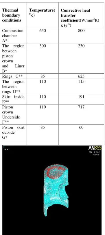
In the present work the thermal boundary conditions are selected based on the literature (Ekrem Buyukkaya, Thermal analysis of pistons). The variation of temperature over the surface of the piston is presented in figure (5.3)
Figure (5.3) Thermal boundary conditions
Table (5.3.1) Thermal boundary conditions for piston TEMPERATURE DISTRIBUTION IN CAST IRON PISTION
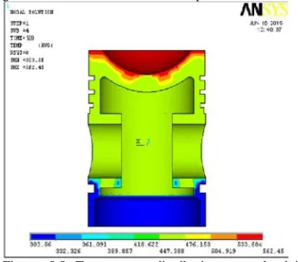
The temperature distributions in cast iron piston for the given boundary conditions are shown in figure 5.4 and from the figures the maximum temperature is observed on cast iron piston the temperature distributions less than the brass piston and aluminium piston.
Figure 5.4 Temperature distribution of cast iron piston TEMPERATURE DISTRIBUTION IN ALUMINIUM PISTON
The temperature distribution in aluminium piston for the same given boundary conditions is shown in figure 5.5 and from the figures it is observed that the Thermal
boundary conditions
Temperature(
oc) Convective heat
transfer
coefficient(W/mm2K) x (e-6)
Combustion chamber A*
650 800
The region between piston crown and Liner B*
300 230
Rings C** 85 625
The region between rings D**
110 115
Skirt inside E**
110 191
Piston crown Underside F**
110 717
Piston skirt outside G*
temperature distribution on the aluminium piston is greater than the cast iron and brass piston.
Figure 5.5 Temperature distributions on aluminium piston
TEMPERATURE DISTRIBUTION IN BRASS PISTON
The temperature distributions in brass piston for the same given boundary conditions are shown in figure 5.6 and from the figures it is observed that the temperature distribution on the brass piston is less than the aluminium piston and greater than the cast iron piston.
Figure 5.6 Temperature distribution of brass piston SUMMARY
In this chapter the temperature distribution on the piston using finite analysis for different materials are presented. The cast iron piston is showing higher temperatures on piston surfaces than other two materials due to its lower thermal conductivity.
VIII STATIC ANALYSIS ON PISTONS IN CATIAV5
Static analysis:
Generative structural analysis is useful to acquire the various structural characteristics of your parts and products in a 3D environment. Using these tools allows you to analyze your parts or products to determine their structural qualities before they are manufactured. The Generative Structural Analysis workbenches utilize the Finite Element Method of numerical approximation. This method works by approximating the model by breaking it down into smaller, more simplified pieces. These broken down pieces are referred to as elements. Elements are connected together at what are commonly known as nodes.
7.1 Static case analysis for aluminium piston in catia v5
Figure 7.1.1 von mises stress nodal values for aluminium piston
Strain energy= 1.597x10-013j
Figure 7.1.2 estimated local errors for aluminium piston
7.2 Static case analysis for cast iron piston in catia v5 Extreme Values
Min: 0.353162 N/m2 Max: 36.4016 N/m2
Figure 7.2.1 von mises stress nodal values for cast iron piston Strain energy: 9.211x10-014j
Figure 7.2.2 estimated local errors for cast iron piston
7.3 Static case analysis for brass piston in catia v5 Extrema Values
Min: 0.362491 N/m2 Max: 35.3534 N/m2
Figure 7.3.1 von mises stress nodal values for brass piston
Strain energy= 8.538x10-014J
Figure 7.3.2 estimated local errors for cast iron piston
IX RESULT AND DISCUSIONS
For thermal barrier engines, heat conduction is generally more dominant than radiation; hence, the thermal conductivity and specific heat of the material is very important for estimating temperature distributions.
The finite element results show that the cast iron piston is showing maximum surface temperature than Aluminium and brass pistons for selected same boundary conditions.
It is due to the lower thermal conductivity of the cast iron material than the other two materials.
Because of that it doesn’t allow much heat to pass
the top surface of the piston and based upon the static analysis cast iron piston obtained out of permissible limits of stress and strain energy is less than the other two materials. It due to the boundary conditions
Though the thermal conductivity of cast iron material is less, its specific heat is higher than brass which indicates that it cannot hold heat for longer time.
From the specific point of view brass material is having low specific heat which indicates that it can hold heat for more time and the some can be transferred to the incoming charge in the next stroke. Though the thermal conductivity of brass material is more than the cast iron, it is more suitable for the burning of low certain fuels which requires higher temperatures. And based upon the static analysis brass piston have permissible limit of stress and strain energy is less than the aluminium piston and greater than the cast iron. It is due to the density of material.
But for aluminium both specific heat and thermal conductivity is more, so it transfers more heat through the material itself. And based upon the static analysis aluminium piston have with in the permissible limit of stress and strain energy is greater than the brass piston and cast iron. It is due to the low density of material.
The comparison of the maximum temperature observed on the top surface of the various piston materials for the same thermal boundaries conditions are given in table 8.1.
Piston Materials
Maximum temperature(oC)
Minimum temperature(oC)
Cast iron 642 615
Aluminium 562 533
Brass 590 560
Table(8.1) Maximum and minimum temperatures observed on top surface of the piston for different Materials.
X CONCLUSIONS
In the diesel engines, the maximum power generation and reduced pollutions mainly depends on the piston modifications only. The power generation further depends on the temperature distributions through that. So in this work a comparative evaluation was made between the temperature distributions of various piston materials and also static analysis for same boundary conditions
According to the simulation results conducted in this study, it has been conclude that the cast iron material shows higher surface temperatures and stress
distribution and it will transfer more heat to the exhaust gases due to its higher specific heat than brass materials
As the self ignition temperature of the diesel is lower and for higher efficiency aluminum piston is more suitable for the diesel engines due to its low density. But for burning of certain fuels as an alternate for diesel it requires higher heats and the brass piston is more suitable though the density is higher than the remaining two materials.
XI REFERENCES
1.
J.B.Heywood, Internal combustion engine fundamentals, McGraw-Hill, 1988.2.
E.Buyukkaya and M.Cerit, “Thermal analysis of adiesel engine piston using 3-D finite element method.