TECHNICAL UNIVERSITY OF CLUJ-NAPOCA
ACTA TECHNICA NAPOCENSIS
Series: Applied Mathematics, Mechanics, and Engineering Vol. 61, Issue II, June, 2018
RESEARCH OF INDUSTRIAL PROCESSES IN AUTOMATION
Dan BIZUBAC, Marcel Sabin POPA, Bernd Otto HÖRMANN, Adrian Sorin FAUR
Abstract: Industrial automation of an installation or process can be considered as control application processes or computer systems applications. The world of industrial automation has progressed rapidly over the last decades and the growth, maturity is driven by technological advances, high expectations from the user and the fresh maturity of the industrial processing technologies. Industrial automation is a vast and diverse discipline, comprising processes, machines, electronics, software and computer systems that work together towards a common set of objectives (increasing production, improving quality, reducing costs and maximizing flexibility). The research will be divided into 4 stages and will be carried out with the support of the Technical University of Cluj-Napoca.
Key words: Automation, Industrial Automation, Process, Lifecycle, Manufacturing
1. INTRODUCTION
Industrial automation or automated control is the use of different control systems for operating equipment such as machinery, plant processes, boilers and heat furnaces, as well as handling, distribution in the telephone networks, steering and stabilization of ships, planes and many other applications with minimal or reduced human intervention. Some processes have been completely automated.
The greatest benefit of industrial automation is that it saves work; however, automated industrial processes are also used to save energy and improve quality, accuracy and precision. One of the simplest types of control is on-off control. An example is the thermostats used on household appliances. The electromechanical thermostats used in HVAC may only have a start / stop switch for heating or cooling systems. Electronic controllers can add several steps for heating and variable fan speed control.
In sequential control, a programmed sequence of discrete operations is performed, often based on a logical system involving system states. A lift control system is an example of a control sequence.
The advanced type of automation that revolutionized the industrial process of manufacturing, aircraft construction,
communications, and other industries is the feedback control, which is usually continuous and involves performing measurements using a sensor and making adjustments to maintain the measured variable within a set interval.
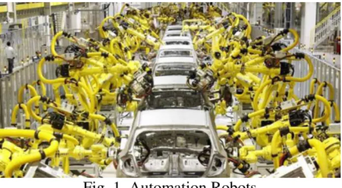
Fig. 1. Automation Robots
1.1.Open and closed loop
All the constituent elements for the measurement and control of a single variable are called a control loop. The control uses a measured signal and compares it with a set point, then calculates and sends a return signal to make a correction. This is called a closed-loop control. If the operator does not incorporate feedback to make a correction, then the loop is open.
1.2.Sequential control and logical sequence or system state control
Sequential control can be either a fixed sequence or a logical sequence that will perform different actions depending on the different states of the system. An example of an adjustable but otherwise fixed sequence is a timer on a sprinkler.
States refer to the different conditions that may occur in a usage or a sequence in a system scenario. One example is a lift that uses system-based logic to perform certain actions in response to its input and operator. For example, if the operator presses the lower button, the system will respond to whether the lift is on or off, going up or down, or when the door is open or closed.
An early development of sequential control was the logic of the relay, through which the electrical relays work with electrical contacts that either start or interrupt the power of a device. The relays were used for the first time in telegraph networks before being developed to control other devices, such as turning on and off large industrial motors or opening and closing the electrovalves. These were more flexible in their response than the rigid single-frame cameras. Other more complicated examples involved in maintaining safe sequences for the devices would be swing bridge controls. The total number of relays, cam timers and drum sequencers can number into the hundreds or even thousands in some factories. Early programming techniques and languages were needed to make such systems manageable, one of the first being ladder logic, where diagrams of the interconnected relays resembled the rungs of a ladder. Special computers called programmable logic controllers were later designed to replace these collections of hardware with a single, more easily re-programmed unit.
1.3.Automation tools
Engineers can now have numerical control over automatic devices. The result is a wide range of applications and human activities. Computer-assisted technologies (or CAx) now serve as the basis for mathematical and
organizational tools used to create complex systems. Notable examples of CAx include computer aided design (CAD software) and computer aided manufacturing (CAM) software. Improved design, analysis, and fabrication of CAx products have been beneficial to the industry.
Information technology, along with industrial machinery and processes, can help design, implement and monitor control systems. An example of an industrial control system is a programmable logic controller (PLC). PLCs are specialized computers that are commonly used to synchronize the flow of inputs from sensors and events (physical) to outputs to servomotors and events.
Fig. 2. Automation Robots
Human Machine Interfaces (HMI) or Human-Computer Interfaces (CHI), previously known as human machine interfaces, are commonly used to communicate with PLCs and other computers. Service staff who monitor and control through the HMI can be named by different names on a case-by-case basis. In process and industrial environments, they are called operators or something like that. In central heating and central utilities departments are called stationary engineers. Different types of automation tools exist:
• ANN - Artificial neural network • DCS - Distributed Control System • HMI - Human Machine Interface
• SCADA - Supervisory Control and Data
• PLC - Programmable Logic Controller • Instrumentation
• Motion control • Robotics
1.4.Limitations to automation
• Current technology is unable to automate
all the desired tasks.
• Many operations using automation have
large amounts of invested capital and produce high volumes of product, making malfunctions extremely costly and potentially hazardous. Therefore, some personnel are needed to insure that the entire system functions properly and that safety and product quality are maintained.
• As a process becomes increasingly
automated, there is less and less labor to be saved or quality improvement to be gained. This is an example of both diminishing returns and the logistic function.
• As more and more processes become
automated, there are fewer remaining non-automated processes. This is an example of exhaustion of opportunities. New technological paradigms may however set new limits that surpass the previous limits.
1.5.Current limitations
There are now many roles for people in industrial processes beyond the automation sphere. Tasks requiring subjective assessment or synthesis of complex sensory data such as smells and sounds, as well as high-level activities such as strategic planning, currently require human expertise. In many cases, the use of a man is more cost-effective than mechanical approaches even when automation of industrial tasks is possible. Overcoming these obstacles is a way to be theorized post-deficit economy.
2. INDUSTRIAL AUTOMATION
Industrial automation is primarily concerned with manufacturing automation,
quality control and material handling processes. General process controllers for industrial processes include programmable logic controllers and computers. A trend is to increase the use of machines to provide automated control functions; another is a continuous increase in the use of robots.
Energy efficiency in industrial processes has become a higher priority. Semiconductor companies such as Infineon Technologies offer 8-bit microcontrollers for motor control applications, general purpose pumps and fans to reduce power consumption and thus increase efficiency.
2.1.Manufacturing Execution Systems
Manufacturing Execution Systems (MES) are computer systems used in manufacturing. MES can provide accurate information at the right time and shows the manufacturing decision maker "how can the current factory conditions be optimized to improve production output." MES works in real-time to allow control of several elements of the production process (e.g. entries, staff, machines, and support services).
An MES system could operate on a number of functional areas, for example: Product Product Lifecycle Management, Resource Planning, Order Execution and Shipment, Production Analysis for Equipment Efficiency Efficiency (EEE), as well as tracking the location of the materials.
The idea of the MES could be seen as an intermediate step between a control system and an enterprise resource planning (ERP) system, as well as supervision and acquisition of data (SCADA).
2.2.Benefits
"Manufacturing Execution Systems create flawless manufacturing processes and provide real-time feedback of requirement changes," and provide information at a single source. Other benefits from successful MES implementation might include:
• Reduced waste, re-work and scrap,
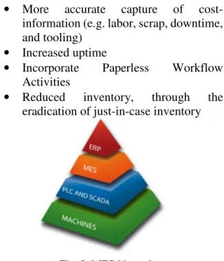
• More accurate capture of
cost-information (e.g. labor, scrap, downtime, and tooling)
• Increased uptime
• Incorporate Paperless Workflow
Activities
• Reduced inventory, through the
eradication of just-in-case inventory
Fig. 3. MES hierarchy
A wide variety of systems use data collected for a dedicated purpose. The further development of these systems during the 1990s introduced overlapping functionality. Then the Manufacturing Enterprise Solutions Association (MESA) introduced a structure by defining 11 functions that determine the scope of the MES. In 2000, the ANSI / ISA-95 standard merged this model with the Purdue reference model (PRM). A functional hierarchy was defined in which the MES was at level 3 between ERP at level 4 and process control at levels 0, 1, 2. With the publication of the third aspect of the standard in 2005, Level 3 activities were divided into four main operations: production, quality, logistics and maintenance.
2.3.Product Lifecycle
In the industry, product lifecycle management (PLM) is the process of managing the entire lifecycle of a product from its inception through design and manufacture, to the service and disposal of manufactured products. PLM integrates individuals, data, processes and business systems and provides an informational log for their companies and their extensive enterprise.
The PLM systems help organizations cope with the growing complexity and challenges of
developing new products for global competition markets.
Product Lifecycle Management (PLM) should be differentiated from Product Marketing (PLCM). PLM describes the engineering aspect of a product, from managing the product descriptions and properties, by developing and PLCM refers to the commercial life of a product on the business market in terms of costs and sales measures.
Product lifecycle management can be considered one of the four cornerstones of a manufacturing corporation's information technology structure. All companies need to manage communications and information with their customers (CRM-customer relationship management), their suppliers and fulfillment (SCM-supply chain), their resources within the enterprise (ERP-enterprise resource planning) and their product planning and development (PLM).
Documented benefits of product lifecycle management include:
• Reduced time to market • Increase full price sales
• Improved product quality and reliability • Reduced prototyping costs
• More accurate and timely request for
quote generation
• Ability to quickly identify potential sales
opportunities and revenue contributions
• Savings through the re-use of original
data
Fig. 4: A generic lifecycle of products
• Savings through the complete integration
of engineering workflows
• Documentation that can assist in proving
compliance for RoHS or Title 21 CFR Part 11
• Ability to provide contract
manufacturers with access to a centralized product record
• Seasonal fluctuation management • Improved forecasting to reduce material
costs
• Maximize supply chain collaboration.
2.4.Phases of product lifecycle and corresponding technologies
Many software solutions have been developed to organize and integrate the different phases of a product’s lifecycle. PLM should not be seen as a single software product but a collection of software tools and working methods integrated together to address either single stages of the lifecycle or connect different tasks or manage the whole process. Some software providers cover the whole PLM range while others single niche application. Some applications can span many fields of PLM with different modules within the same data model. The simple classifications do not always fit exactly, many areas overlap and many software products cover more than one area or do not fit easily into one category. One of the main goals of PLM is to collect knowledge that can be reused for other projects and to coordinate simultaneous concurrent development of many products. It is about business processes, people and methods as much as software application solutions. Although PLM is mainly associated with engineering tasks it also involves marketing activities such as product portfolio management (PPM), particularly with regards to new product development (NPD). There are several life-cycle models in industry to consider, but most are rather similar.
• Phase 1: Conceive
Imagine, specify, plan, and innovate
The first stage is the definition of the product requirements based on customer, company, market and regulatory bodies’ viewpoints. From this specification, the product's major technical
parameters can be defined. In parallel, the initial concept design work is performed defining the aesthetics of the product together with its main functional aspects. Many different media are used for these processes, from pencil and paper to clay models to 3D CAID computer-aided industrial design software.
In some concepts, the investment of resources into research or analysis-of-options may be included in the conception phase – e.g. bringing the technology to a level of maturity sufficient to move to the next phase. However, life-cycle engineering is iterative. It is always possible that something doesn't work well in any phase enough to back up into a prior phase – perhaps all the way back to conception or research. There are many examples to draw from.
• Phase 2: Design
Describe, define, develop, test, analyze and validate
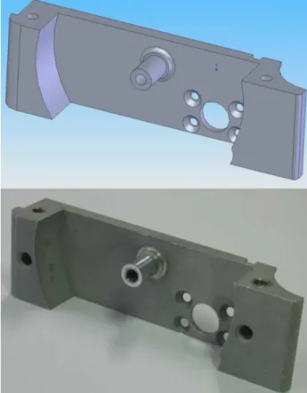
This is where the detailed design and development of the products form starts, progressing to prototype testing, through pilot release to full product launch. It can also involve redesign and ramp for improvement to existing products as well as planned obsolescence. The main tool used for design and development is CAD. This can be simple 2D drawing / drafting or 3D parametric feature based solid/surface modeling. Such software includes technology such as Hybrid Modeling, Reverse Engineering, KBE (knowledge-based engineering), NDT (Nondestructive testing), and Assembly construction.
such as Dimensional tolerance (engineering) analysis. Another task performed at this stage is the sourcing of bought out components, possibly with the aid of procurement systems.
Fig. 5: CAD model and CNC machined part
• Phase 3: Realize
Manufacture, make, build, procure, produce, sell and deliver
Once the design of the product’s components is complete, the method of manufacturing is defined. This includes CAD tasks such as tool design; including creation of CNC Machining instructions for the product’s parts as well as creation of specific tools to manufacture those parts, using integrated or separate CAM (computer-aided manufacturing) software. This will also involve analysis tools for process simulation of operations such as casting, molding, and die-press forming. Once the manufacturing method has been identified CPM comes into play. This involves CAPE (Computer Aided Production Engineering) or CAP/CAPP (Computer Aided production planning) tools for carrying out factory, plant and facility layout and production simulation e.g. press-line simulation, industrial ergonomics, as well as tool selection management. Once
components are manufactured, their geometrical form and size can be checked against the original CAD data with the use of computer-aided inspection equipment and software. Parallel to the engineering tasks, sales product configuration and marketing documentation work take place. This could include transferring engineering data (geometry and part list data) to a web based sales configurator and other desktop publishing systems.
• Phase 4: Service
Use, operate, maintain, support, sustain, phase-out, retire, recycle and disposal
The final phase of the lifecycle involves managing "in-service" information. This can include providing customers and service engineers with the support and information required for repair and maintenance, as well as waste management or recycling. This can involve the use of tools such as Maintenance, Repair and Operations Management (MRO) software.
Whether it be disposal or destruction of material objects or information, this needs to be carefully considered since it may be legislated and hence not free from ramifications.
3. CONCLUSIONS
The study for the industrial process automation is started with some basic concepts and it is desired to implement the entire lifecycle of a product within an automation system with an MES system. This research will be achieved with the support of Technical University of Cluj-Napoca.
4. ACKNOWLEDGMENTS
The authors wish to thank to the Technical University of Cluj-Napoca for the support they offered.
5. REFERENCES
2. Meyer, Heiko; Fuchs, Franz; Thiel, Klaus (2009). Manufacturing Execution Systems: Optimal Design, Planning, and Deployment. New York: McGraw Hill. ISBN 9780071623834.
3. Vinhais, Joseph A. (September 1998). "Manufacturing Execution Systems: The One-Stop Information Source". Quality Digest. QCI International. Retrieved March 7, 2013.
4. Blanchard, Dave (March 12, 2009). "Five Benefits of an MES". Industry Week. Retrieved March 7, 2013.
5. Kurkin, Ondřej; Januška, Marlin (2010). "Product Life Cycle in Digital factory". Knowledge management and innovation: a business competitive edge perspective. Cairo: International Business Information Management Association (IBIMA): 1881–1886. ISBN 9780982148945.
6. "About PLM". CIMdata. Retrieved 25 February 2012.
7. "What is PLM?” PLM Technology Guide. Retrieved 25 February 2012. 8. Cunha, Luciano (20 July 2010).
"Manufacturing Pioneers Reduce Costs By Integrating PLM & ERP". onwindows.com. Retrieved 7 February 2017.
9. Wong, Kenneth (29 July 2009). "What PLM Can Learn from Social Media". Retrieved 7 February 2017.
10.Hill, Jr., Sidney (May 2003). "How To Be A Trendsetter: Dassault and IBM PLM Customers Swap Tales From The PLM Front". COE newsnet. Archived from the original on 13 February 2009. Retrieved 7 February 2017.
11.Pearce, John A.; Robinson, Richard B. (1991). Formulation, implementation, and control of competitive strategy (4 ed.). Irwin. p. 315. ISBN 978-0-256-08324-8. Retrieved 7 February 2017. 12."Projects Past". Brian's Blog. 16
September 2013. Retrieved 7 February 2017.
13.Karniel, Arie; Reich, Yoram (2011). Managing the Dynamic of New Product Development Processes. A new Product
Lifecycle Management Paradigm. Springer. p. 13. ISBN 978-0-85729-569-9. Retrieved 25 February 2012.
14.Evans, Mike (April 2001). "The PLM Debate". Cambashi. Retrieved 4 July 2017.
15.Day, Martyn (15 April 2002). "What is PLM". Cad Digest. Retrieved 25 February 2012.
16.MES Functionalities and MRP to MES Data Flow Possibilities. White Paper Number 2. MESA International, 1994. 17.ANSI/ISA-95.00.01-2000.
Enterprise/Control System Integration – Part 1 Models and Terminology.
18.ANSI/ISA-95.00.02-2000.
Enterprise/Control System Integration – Part 2 Object Model Attributes.
19.ANSI/ISA-95.00.03-2005.
Enterprise/Control System Integration – Part 3 Models of Manufacturing Operations Management.
20.Cox, III, James F., Blackstone, Jr., J.H., 1998. APICS Dictionary, Ninth ed. APICS.
21.Williams, T.J., 1992. The Purdue Enterprise Reference Architecture: A Technical Guide for CIM Planning and Implementation. ISA.
22.Anderson, N.A., 1998. Instrumentation for Process Measurement and Control, Third ed. CRC Press.
23.ANSI/ISA-5.1-1984 (R1992) – Instrumentation Symbols and Identification.
24.Enterprise – control systems integration – ISA.
25.Boyes, W. (Ed.), 2003. Instrumentation Reference Book. Third ed. Butterworth-Heinemann.
26.Coggan, D.A. (Ed.), 2005. Fundamentals of Industrial Control. Second ed. ISA, Practical Guides for Measurement and Control Series.
27.Stuart A. Boyer SCADA Supervisory Control and Data Acquisition 3rd edition, ISA.
29. Gordon Clarke, Deon Reynders, Practical Modern Scada Protocols.
CERCETĂRII ALE PROCESELOR INDUSTRIALE ÎN AUTOMATIZARE
Automatizari industriale de instalare sau procesul poate fi considerat ca procesele de control sau aplicaţii de sisteme informatice. Lumea de automatizari industriale a progresat rapid în ultimele decenii şi creştere, maturitate este condus de progresele tehnologice, aşteptări ridicate de utilizator şi maturitatea proaspete de tehnologii industriale de prelucrare. Automatizari industriale este o disciplină vast şi divers, care cuprinde procese, mașini, electronice, sisteme software si calculatoare, care lucrează împreună spre un set comun de obiective (creşterea producţiei, îmbunătăţirea calităţii, reducerea costurilor şi maximizând flexibilitate). De cercetare va fi împărţit în 4 etape şi vor fi efectuate cu sprijinul universităţii tehnice din Cluj-Napoca.
Dan BIZUBAC, Phd. Student Eng., Technical University of Cluj-Napoca, Department of Manufacturing Engineering, Muncii Blvd 103-105, Tel: 0040.2640.0641, Cluj-Napoca, ROMANIA,.