TECHNICAL UNIVERSITY OF CLUJ-NAPOCA
ACTA TECHNICA NAPOCENSIS
Series: Applied Mathematics, Mechanics, and Engineering Vol. 63, Issue I, March, 2020
DESIGNING AND MANUFACTURING A DELTA ROBOT FOR PICK AND
PLACE APPLICATIONS
Florin COVACIU
Abstract: In this paper it is presented in brief the design and manufacturing for a Delta robot with 3 degrees of freedom. Fusion 360 software was used to design the robotic system, and with the help of a 3D printer, the components of the robotic system were built. With the help of the ideaMaker program 3D printing was done. After assembling the robotic system and create control for this robot, the servo motors on the robot base were actuated for the final tests. With the help of these tests, the performance of the robotic system was validated.
Key words: Delta robotic system, degree of freedom, design, 3D printer, pick and place, manufacture.
1. INTRODUCTION
In practice a robot it is controlled by a computer or microcontroller and is usually an electro-mechanical machine. In the control of the robot, a program is used that controls the actions of the robot, providing information on the tasks that the robot must perform [1]. The categories in which the robots can fit are manual, semiautonomous and autonomous, and can also be controlled remotely being used in many tasks. Two different kinds of robots are the most used, namely: service and industrial robots. The industrial robot was defined by the ISO standard as a manipulator that is automatically controlled, programmable and can have multiple axes. Sensors as well as communication interfaces are required for a robot to perform its tasks. Industrial robots are designed to move tools, parts and materials. Service robot, on the other hand is a robot that operates semi or fully autonomously to perform services useful to the well-being of humans [2]. To build robots we need to have knowledge of mechanical engineering, electrical engineering [3], systems and industrial engineering, computer science, economics, and mathematics [4].
Research in the area of robotics can be done on the kinematics, dynamic and control side, being
base. Serial robots are used in applications that require repetitive task over period of time. The parallel robot can be defined as a combination of cinematic chains with a closed loop. For this kind of robot, the gripper is connected to the fixed base by more than one kinematic chain independent. Parallel structures have been used in applications like machining centers, walking machines, mining machines, adjustable articulated trusses, airplane simulators, etc. [7].
2. DESIGNING OF THE COMPONENTS OF THE DELTA ROBOT
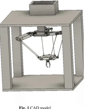
The Delta robotic structure (figure 1) is designed in the Fusion 360 program and this structure has 3 degrees of freedom. The Fusion 360 program is designed by Autodesk being a complex program that can be used both for modeling 3D objects and for finite element analysis. Also, with the help of this program can be done manufacturing, animation and rendering. With this program we can edit components without starting from scratch even if the specifications change, giving the designer a very good editing tool [8].
Fig. 1 CAD model
The robotic structure is made up of the following main components:
• Mobile base
Fig. 2 Mobile base
On this mobile base of the robotic structure is attached six arms and a gripper. The mobile base of the robotic structure can be controlled with the help of the six arms, and with the help of the gripper can take small objects.
• Support for arms
Fig. 3 Support for arms
• Fixed base
Fig. 4 Fixed base
To this base three servo motors are attached.
3. MANUFACTURING AND ASSEMBLING OF THE PARTS
3.1 Introducing the CAD components of the Delta robot structure into ideaMaker printer software
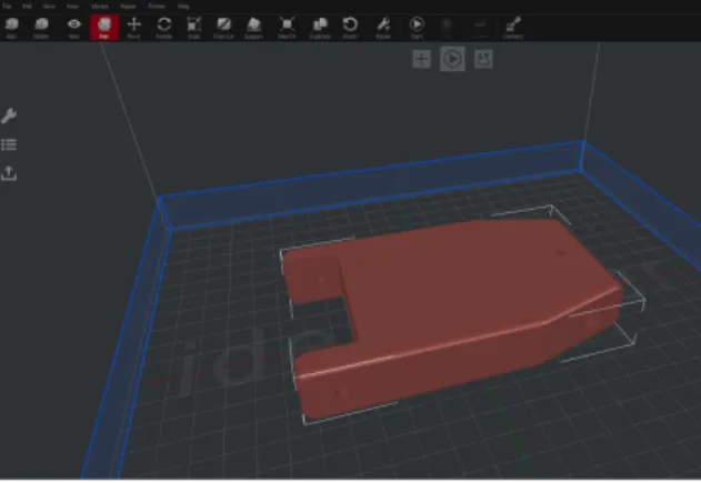
After the components of the Delta robotic structure were designed in the Fusion 360 software, these components needed to be saved in the stl. Extension (figure 5) so they can be imported into the IdeaMaker slicing engine software, which is illustrated in figure 6.
Fig. 5 Component saved with stl. extension
IdeaMaker is one of many slicing platforms, but what distinguishes it is its sleek compatibility with highly customizable print settings, provide limitless customization for advanced users. This
software is available for Windows, Linux, and Mac operating systems (OS). Slicing with ideaMaker is fast, efficient, and completely free because this software is open source. A program with free license can be used for commercial purpose, because commercial is not like that proprietary, as they are based on different rules. The list of open source software is a wide one, covering a wide range of domains, like networking and internet, games, educational, media, artificial intelligence (robotics), programming, security and so on [9].
The main features for ideaMaker software are [10]:
• remote monitoring and print job management;
• the parts in assemblies can be separated automatically;
• as an input it accepts the 3MF / OBJ / STL format, and as output is the G code format;
• generate automatic support structures;
• view cross-sections of models.
Fig. 6 ideaMaker slicing engine software
3.2 Creating and assembling components
surface [12]. Was made a choice of the materials with which 3D printing has been made before components have been created for the delta robotic structure. There are two types of dominant material, namely Acrylonitrile Butadiene Styrene (ABS) and Polylactic Acid (PLA). They are called as thermoplastics, at a normal temperature these materials are solid and when are heated they become soft and shapeable, and this process can be repeated many times. These materials are widespread because of their ability to melt and can be processed again.
General characteristics for PLA and ABS
PLA - is biodegradable and are made through two different processes: condensation and polymerization. The users who print are attracted by a wide range of colors and a translucencies and glossy sensation. Many users prefer the semi-sweet smell and the plant-based origins rather than ABS. The PLA material under proper cooling conditions gives the impression that it has higher printing speeds, clearer corners and lower layer heights. This is a popular plastic used more for the hobbyists, having a low deformation of the pieces.
ABS - is a common thermoplastic well known in the injection molding industry. The natural ABS material has a beige color before adding colorants. With this material due to the flexibility can be created interlocking pieces or pieces connected with pin [13].
We chose the PLA material for 3D printing after we analyzed the two materials (PLA and ABS). In the following images we can see components of the Delta structure that were created by 3D printing.
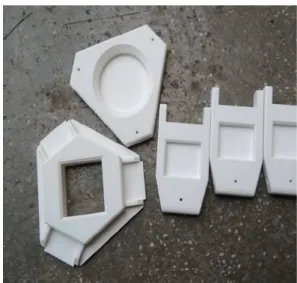
After the appropriate 3D print settings have been made in the ideaMaker environment, 3D printing has been released. In figure 7 we can see the main components of the Delta robotic system that were made with the 3D printer.
Fig. 7 Main components of the Delta robotic system
Assembling the robot
After the pieces of the Delta system were created using the 3D printer, various devices were attached to these components as follows:
• Fixed base
On the fixed base of the robotic system, three servo motors were attached (figure 8). These servo motors control the Delta robotic system.
Fig. 8 Fixed base • Mobile base
material (figure 9), through which this base can be positioned at different angles.
Fig. 9 Mobile base
• Arm
On each arm that is built using the 3D printer are attached two long beam. (figure 10). This long beam is made of the threaded rod that enters in the spherical joints of the parallel robot. The threaded rod was purchased at a longer length and then cut to the desired size.
Fig. 10 Arm
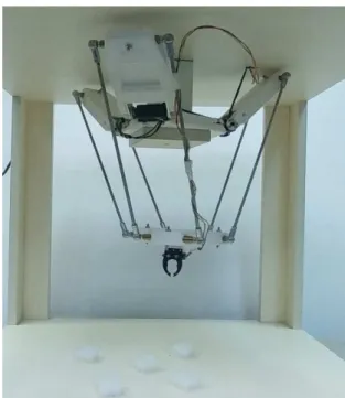
After attaching the necessary devices to the components of the robotic system, it went to the next stage, namely, to assemble the entire Delta robotic system (figure 11). This robotic system is designed for pick and place applications, and via a gripper this robot can handle small-sized objects.
Fig. 11 The Delta robotic system
4. CONCLUSIONS
The paper presents design and manufacturing of a Delta robotic structure. The components of this structure were first designed in Fusion 360 program, after which they were manufactured using the 3D printer technology. After manufacturing the components, the robotic structure has been assembled and tests have been made for its functionality by actuating the servo motors. Performed tests have validated the robotic system performances.
ACKNOWLEDGMENT
The paper presents results from the research activities of the project ”Entrepreneurial competences and excellence research in doctoral and postdoctoral studies programs - ANTREDOC”, code: POCU/380/6/13/123927, co-financed by the European Social Fund through the Human Capital Operational Program 2014-2020, Priority Axis 6: Education and skills, "Support for post-doctoral students and researchers". Beneficiary: Technical University of Cluj-Napoca / Partner: ROBERT BOSCH SRL.
5. REFERENCES
[1] Olawale, J., Oludele, A., Ayoudele, A., Development of a Microcontroller Based Robotic Arm, Proceedings of the 2007 Computer Science and IT Education Conference, pp. 550-557, 2007
[2] Elfasakhany, R., Yanez, E., Baylon, K., Salgado, K., Design and Development of a Competitive Low-Cost Robot Arm with Four Degrees of Freedom, Modern Mechanical Engineering, vol. 1, pp. 47-55, doi: 10.4236/mme.2011.12007, 2011
[3] Iordan, A.E.,Interactive Software Design for Shaping Electrical Circuits utilizing Graphs, Annals of Faculty Engineering Hunedoara, vol. 13, pp. 175-178, ISSN 1584-2673, 2015 [4] Iordan, A.E., Panoiu, M., Multimedia
Educational Software for Producing Graphs of Mathematical Functions, International Journal of Computers, Comunications and Control, vol. 1, pp. 284-289, ISSN 1841-9836, 2006
[5] Deteşan, O., The dynamic modelling of the robot mechanical structure using the symbolic computation in Matlab, Acta Tehnica Napocensis, Series: Applied Mathematics and Mechanics, vol. 56, Issue IV, ISSN 1221-5872, pp. 659-664, Cluj-Napoca, România, 2013
[6] Schonstein, C., Kinematic control functions for a serial robot structure based on the time derivative jacobian matrix, Acta Tehnica Napocensis, Series: Applied Mathematics and Mechanics, vol. 61, Issue II, ISSN 1221-5872, pp. 253-660, Cluj-Napoca, România, 2018
[7] Pandilov, Z., Dukovski, V., Comparison of the characteristics between serial and
parallel robots, ACTA TECHNICA
CORVINIENSIS – Bulletin of Engineering, vol. 1, Issue VII, ISSN: 2067 – 3809, 2014 [8] ***,
www.autodesk.com/products/fusion-360/students-teachers-educators
[9] Timoftei, S., Brad, E., Sarb, A., Stan, O., Open-source software in robotics, Acta Tehnica Napocensis, Series: Applied Mathematics and Mechanics, vol. 61, Issue III, ISSN 1221-5872, pp. 519-626, Cluj-Napoca, România, 2018
[10] ***, raise3d.com/pages/ideamaker
[11] Masood, S., Introduction to Advances in
Additive Manufacturing and Tooling,
Comprehensive Materials Processing. vol.10, Advances in Additive Manufacturing and Tooling, pp. 1–2, ISBN: 978-0-08-096533-8, 2014
[12] Popescu, D., Popişter, F., Eles, A., Comes, R., Improving the quality of plastic parts obtained by 3d printing, Acta Tehnica Napocensis, Series: Applied Mathematics and Mechanics, vol. 58, Issue I, ISSN 1221-5872, pp. 25-30, Cluj-Napoca, România, 2015
[13] ***,allthat3d.com/pla-vs-abs/
[14] Vertutt, J., Liegeois, A., General design criteria for manipulators, Mechanism and Machine Theory, vol. 16, Issue 1, pp. 65-70, doi.org/10.1016/0094-114X (81)90052-5, 1981
[15] Drumright, R., Ruber, P., Henton, D., Polylactic acid technology, Advanced Materials, vol. 12, Issue 23, pp. 1841-1846, ISSN: 0935-9648, 2000
PROIECTAREA SI FABRICAREA UNUI ROBOT DELTA PENTRU APLICATII DE PICK AND PLACE
Rezumat: Lucrarea prezintă proiectarea și fabricarea unui sistem robotizat Delta, cu trei grade de libertate. Sistemul robotic a fost proiectat folosind programul Fusion 360, apoi componentele sistemului robotic au fost fabricate folosind imprimanta 3D. Pentru mediul de imprimare 3D a fost folosit programul ideaMaker. După asamblarea sistemului robotic și crearea controlului pentru acest robot, s-au efectuat teste pentru funcționalitate prin acționarea servomotoarelor atașate pe baza fixă. Aceste teste au validat performanțele sistemului robotic.