Rev.1/01.03.2010 Page 1 of 10 BA61300GB.doc
Operating
Instructions
Cylinder
Instruction manual
In-line Sight Glasses
100002749
Date of issue: September 2020
First published: September 2020
Instruction manual Page 3 In-line Sight Glasses, 100002749
Contents
1
Symbols used ... 5
2
Sectional drawing ... 6
3
Use and operating principle ... 7
4
Transport ... 7
4.1
Checking the delivery contents ... 7
4.2
Transport ... 7
5
Safety advice ... 8
6
Installation / disassembly/ assembly ... 8
6.1
Installation ... 8
6.2
Disassembly ... 9
6.3
Assembly ... 9
7
Repairs/maintenance ... 10
8
Cleaning ... 10
9
Technical data ... 11
9.1
Variants of the cylinder sight glass ... 11
9.2
Dimensions of cylinder sight glass ... 12
9.3
Pressure strength of the borosilicate glass cylinders ... 13
10
Material and surfaces ... 13
Instruction manual Page 5 In-line Sight Glasses, 100002749
1 Symbols
used
Danger warnings:
Danger warnings are denoted by the danger symbol.
NOTE!
2 Sectional
drawing
7
4
1
5
3
6
8
2
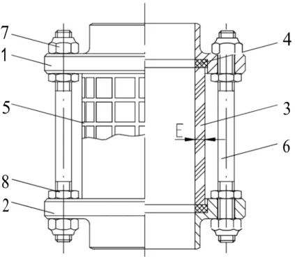
Figure 1 Sectional view of cylinder sight glass DIN SS (example)
Table 1 Bill of material cylinder sight glass DIN SS (example)
1other connection options see 9.1 Variants of the cylinder sight glass 2alternative gasket material upon request
3( ) values in brackets for ON125/150
item Number Designation Item Number Designation
1 1 Connection socketvariants) 1 (different 5 1 Safety screen (optional)
2 1 Connection socketvariants) 1 (different 6 4(6)3 Tension rod
3 1 Glass cylinder borosilicate 7 8(12)3 Self-locking hexagon nut
DIN 985
Instruction manual Page 7 In-line Sight Glasses, 100002749
3
Use and operating principle
The cylinder sight glass serves for visual inspection of liquids in pipelines. An optional safety screen prevents the glass from outer damages and also serves as burst protection. The nominal pressure of the glass depends on the nominal width used (see Table 3 page 13). The cylinder sight glass is available with different
connection variants (see chapter 9.1 Variants of the cylinder sight glass page 11).
4 Transport
4.1 Checking the delivery contents
NOTE!
When you receive the cylinder sight glass, check the delivery against the order to make sure they correspond.
Check that the delivery is complete and check its condition.
If there are visible signs of transit damage and/or packing units are missing notify the forwarding agent immediately in the consignment note.
4.2 Transport NOTE!
• The packing units must only be transported using suitable lifting equipment and slinging gear.
• Pay attention to the graphic symbols on the packaging.
• Transport the cylinder sight glass carefully to prevent damage from sudden impacts; exercise due care when loading/unloading.
5 Safety
advice
Danger warnings:
• Prior to maintenance works, the pipeline system containing the cylinder sight glass must be depressurized and fluid-free!
• Exceeding the max. permissible operating pressure causes a risk of injuries due to bursting of the glass cylinder and escaping of fluids. If necessary, provide pressure relief devices to prevent excessive pressure. The installation location must effectively prevent any risk of injury. If necessary, protective device must be installed in order to prevent accidents.
6 Installation/disassembly/assembly
6.1 Installation
Danger warnings:
• Observe the relevant national guidelines and regulations.
• Install the cylinder sight glass without tension into the pipeline system.
• The valve may only be installed when depressurized.
• Only assemble the device in cooled down and cleaned condition.
NOTE!
(#) refers to position numbers on page 6.
The cylinder sight glass can be installed in any position.
Cylinder sight glasses with screw or threaded connections (cf. Fig.5-8 page 11) are delivered ready to assembly. During the installation in a pipeline system, make sure that the glass sits without tension (with parallel faces and centrically facing pipe connection).
Cylinder sight glasses with welded connections (cf. Fig.3-4 page 11) must be disassembled before assembly. During disassembly make sure to loosen the hexagon nuts (7) carefully and crosswise. After disassembly of the cylinder sight glasses, weld the connection sockets (1,2) to the provided pipe ends (cf. Fig.1 page 6).
Before assembly of the cylinder sight glass, align the pipe ends with the welded connection sockets plan and centered to each other. Only this ensures tension- free installation. When inserting the glass cylinder (3), make sure that it is aligned centrally to the receptacle. Avoid contact between glass and socket by all means. Tighten the hexagon nuts (7) carefully and crosswise. Finally lock the hexagon nuts (7) with the flat hexagon nuts (8).
Instruction manual Page 9 In-line Sight Glasses, 100002749
6.2 Disassembly
Danger warnings:
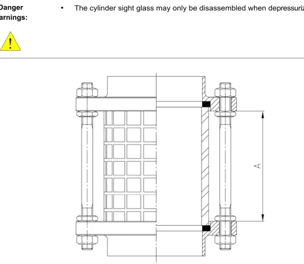
• The cylinder sight glass may only be disassembled when depressurized.
Figure 2 Cylinder sight glass , adjustment dimension A NOTE!
(#) refers to position numbers on page 6.
Determine adjustment dimension A (see Fig.2).
Remove hexagon nut (7) from one side.
Axially disassemble the connection socket (1 or 2), gaskets (4) and glass cylinder (3).
6.3 Assembly
Danger warnings:
• During assembly make sure that no outer forces act on the cylinder sight glass.
• Install the glass cylinder (3) centered.
• Set adjustment dimension A and tighten the hexagon nut evenly and crosswise.
• Pay attention that the planes are parallel.
Assemble in reverse order.
Check fitting for tightness.
If the fitting is not tight, loosen the hexagon nut (8) and tighten the hexagon nut (7) evenly.
7 Repairs/maintenance
Danger warnings:
• The maintenance intervals differ from case to case, the operator should define them by himself basing on sporadic checks.
• To replace the gaskets, refer to the installation instructions (chapter 6 page 8) or the cleaning instructions (chapter 8 page 10).
Alfa Laval cannot accept liability for claims made as a result of non-observance of these Operating Instructions or constructional changes to the cylinder sight glass.
Any other use or use outside the defined scope is considered to be improper use. Alfa Laval will not accept liability for losses incurred as a result of improper use.
8 Cleaning
Danger warnings:
• Observe the safety data sheets by the cleaning agent manufacturer.
Instruction manual Page 11 In-line Sight Glasses, 100002749
9
Technical data
Instruction manual Page 13 In-line Sight Glasses, 100002749
9.3 Pressure strength of the borosilicate glass cylinders
1l theoretical values with proper assembly
10 Material and surfaces
In contact with product: 1.4301/1.4307 AISI 304/304L 1.4404 AISI 316L (optional) Not in contact with product: 1.4301/1.4307 AISI 304/304L
Gaskets: NBR, EPDM or FKM (depending on specification and/or version) Class cylinder: Borosilicate
Inner surface: Depending on specification Outer surfaces: Depending on specification
11 How to contact Alfa Laval Kolding A/S
For further information please feel free to contact:
Alfa Laval Kolding A/S
31, Albuen - DK 6000 Kolding - Denmark Registration number: 30938011
Tel switchboard: +45 79 32 22 00 - Fax switchboard: +45 79 32 25 80 www.toftejorg.com , www.alfalaval.dk - [email protected]
How to contact Alfa Laval Contact details for all countries are continually updated on our website.
Please visit www.alfalaval.com to access the information directly.
© Alfa Laval Corporate AB
This document and its contents is owned by Alfa Laval Corporate AB and protected by laws governing intellectual property and thereto related rights. It is the responsibility of the user of this document to comply with all applicable intellectual property laws. Without limiting any rights related to this document, no part of this document may be copied, reproduced or transmitted in any form or by any means (electronic, mechanical, photocopying, recording, or otherwise), or for any purpose, without the expressed permission of Alfa Laval Corporate AB. Alfa Laval Corporate AB will enforce its rights related to this document to the fullest extent of the law, including the seeking of criminal prosecution.