App Note
SRX High Availability Design Guide
Introduction
The purpose of this design guide is to lay out the different high availability deployment scenarios and provide sample configurations for the different scenarios. The audience for this deployment guide is primarily technical field engineers who will either use this for customer designs, along with proof of concept demos and discussions.
Scope
In this document we are going to cover the four most common high availability scenarios when deploying SRX. • Active/Passive Simple Deployment
• Active/Passive Full Mesh Deployment • Active/Active Deployment
• Active/Passive Transparent Mode Deployment
Equipment Used
App Note
* Note that for the Data Links, in the Active/Active example, we use the 10GbE links rather than the 1GbE links to accommodate interchassis data traffic.
Chassis Layouts: • SPC’s
o Slot 0
o Slot 1 • IOC’s
o Slot 6 (4 x 10GbE)
o Slot 7 (4 x 10GbE)
o Slot 11 (40 x 1GbE)
• SCB
o SCB Slot 0 (with Routing Engine)
o SCB Slot 1
• RE
App Note
Software: JUNOS 9.6 will be used for this guide for Active/Passive (Simple and Full Mesh,) Active/Active, and
Active/Passive Transparent Mode since it is the first release to support A/P L2 Mode. A/A L2 mode will not be supported until 2010. The command “set chassis cluster control-link-recovery” is supported via JUNOS 9.6, so for all of the
examples excluding Active/Passive HA, you can remove this command to configure the clusters in previous versions 9.5 and 9.4.
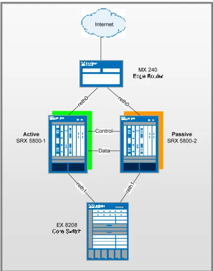
Basic Active / Passive SRX Deployment Scenario
Active/Passive High Availability is the most common type of high availability firewall deployment and consists of two firewall members of a cluster; one of which actively provides routing, firewall, NAT, VPN, and security services, along with maintaining control of the chassis cluster, with the other firewall passively maintaining its state for cluster failover
capabilities should the active firewall become inactive. Basic Active/Passive assumes that we do not have a full mesh deployment scenario on the surrounding networking devices, but rather rely on their internal redundancy such as redundant routing-engines and switch-control-boards.
re th0 reth
0
App Note
Networking Configuration
SRX 5800’s • reth0
o Zone / IP Address: Untrust Zone - 1.1.1.1/24
o SRX 5800-1 Member Interface: xe-6/0/0
o SRX 5800-1 Member Interface: xe-18/0/0 • reth1
o Zone / IP Address: Trust Zone – 2.2.2.1/24
o SRX 5800-1 Member Interface: xe-6/1/0
o SRX 5800-1 Member Interface: xe-18/1/0 • High Availability Interfaces
o Control Port:
Node0: FPC 1 port 0 Node1: FPC 13 port 0
o Data/Fabric Port:
Node 0: ge-11/3/0 Node 1: ge-23/3/0
M240’s
• Untrust-VLAN
o VLAN / IP Address: Interface VLAN.100 / IP Address 1.1.1.254
o Member Interfaces: xe-1/0/0, xe-2/0/0 EX 8208’s
• Trust-VLAN
o VLAN / IP Address: Interface VLAN.50 / IP Address 2.2.2.254/24
o Member Interfaces: xe-1/0/0, xe-2/0/0
SRX Configurations:
Chassis Cluster Configuration
We begin the configuration with the common task of configuring the cluster members to join the cluster. We are going to assume that we are running JUNOS 9.6 for this example on both cluster members, and that they have identical hardware in each chassis. Since we only have a single cluster on the segments, we will just use cluster-id 1, with the SRX 5800-1 being node 0, 5800-2 being node 1. These commands are the only commands where it matters which chassis member you apply them to because the setting is stored in the NVRAM rather than in the configuration itself. The command will also cause the cluster member to reboot, which is required at for current versions of JUNOS. Please note that you must
App Note
issue this command as an operational command, and NOT in configuration mode. The commands that we need to configure are as follows:
SRX 5800-1: set chassis cluster cluster-id 1 node 0 reboot SRX 5800-2: set chassis cluster cluster-id 1 node 1 reboot
*Note if you have multiple SRX clusters on a single L3 broadcast domain, then you much make sure to assign different cluster ID’s to each cluster, or else there will be a MAC address conflict.
Control Port Configuration
Once the chassis members have rebooted, we will now configure the control ports of the clusters. Note that we choose FPC 1 / 13 because the CP is always going to be on the lowest SPC/SPU in the cluster, which in this case is in Slot 0. For maximum reliability, it is recommended to put the Control Ports on a separate SPC from the CP, which is why we choose SPC in Slot 1. As mentioned, all commands going forward are applied on the control plane regardless of which member is active. As of 9.6, this is only required for the SRX 5k platforms, and not the 3k since they used a fixed control port.
set chassis cluster control-ports fpc 1 port 0 set chassis cluster control-ports fpc 13 port 0
Data Fabric Configuration
Now that the control ports are assigned, we must configure the fabric (data) ports of the cluster. These are used to pass RTO’s in Active/Passive mode. Since we are just using this for Active/Passive, there is no advantage to use 10GbE ports, since we will never approach that much bandwidth. Instead, we will just use one of our 1GbE ports. We define two fabric interfaces, one on each chassis (which connect together.)
set interfaces fab0 fabric-options member-interfaces ge-11/3/0 set interfaces fab1 fabric-options member-interfaces ge-23/3/0
Node Specific Configuration
Since the SRX cluster configuration is held within a single common configuration, we need a way to assign some elements of the configuration to a specific member only. This is done in JUNOS with the node specific configuration method called groups. The last command uses the node variable to define how the groups are applied to the nodes (each node will recognize their number and accept the configuration accordingly.) We also configure out of band management on the fxp0 interface of the SRX with separate IP addresses for the individual control planes of the cluster.
set groups node0 set groups node1
set groups node0 system host-name SRX5800-1
set groups node0 interfaces fxp0 unit 0 family inet address 10.3.5.1/24 set groups node0 system backup-router 10.3.5.254 destination 0.0.0.0/0 set groups node1 system host-name SRX5800-2
set groups node1 interfaces fxp0 unit 0 family inet address 10.3.5.2/24 set groups node1 system backup-router 10.3.5.254 destination 0.0.0.0/0
App Note
set apply-groups ${node}
Redundancy Group Configuration
Redundancy Groups are the concept in JSRP clustering that is similar to a Virtual Security Interface in ScreenOS. Basically, each node will have an interface in this group, where only 1 interface will be active at a time. A Redundancy Group is a concept similar to a Virtual Security Device in ScreenOS. Redundancy Group 0 is always for the control plane, while redundancy group 1+ is always for the data plane ports. Since in Active/Passive only 1 chassis member is active at a time, we only define Redundancy Groups 0 and 1. We must also configure how many redundant Ethernet groups we will have active on the device (so that they system can allocate the appropriate resources for it. This is similar to Aggregate Ethernet.
We will also need to define which device has priority (in JSRP high priority is preferred) for the control plane, as well as which device is preferred to be active for the data plane. Remember that the control plane can be active on a different chassis than the data plane in active passive (there isn’t anything wrong with this from a technical standpoint, but many administrators probably feel better having both the control and data-plane active on the same chassis member.
set chassis cluster reth-count 2
set chassis cluster redundancy-group 0 node 0 priority 129 set chassis cluster redundancy-group 0 node 1 priority 128 set chassis cluster redundancy-group 1 node 0 priority 129 set chassis cluster redundancy-group 1 node 1 priority 128
Redundant Ethernet Configuration
We now move on to define the actual data interfaces on the platform so that in the event of a data-plane failover, the other chassis member will be able to take over the connection seamlessly. This configuration involves defining the membership information of the member interfaces to the RETH interface, defining which redundancy group the RETH interface will be a member of (in Active/Passive it will always be 1,) and finally defining the RETH interface information such as the IP Address of the interface.
set interfaces xe-6/0/0 gigether-options redundant-parent reth0 set interfaces xe-6/1/0 gigether-options redundant-parent reth1 set interfaces xe-18/0/0 gigether-options redundant-parent reth0 set interfaces xe-18/1/0 gigether-options redundant-parent reth1 set interfaces reth0 redundant-ether-options redundancy-group 1 set interfaces reth0 unit 0 family inet address 1.1.1.1/24 set interfaces reth1 redundant-ether-options redundancy-group 1 set interfaces reth1 unit 0 family inet address 2.2.2.1/24
Chassis and Interface Monitoring
Now that we have defined our cluster we want to configure how the cluster should behave in failures. You can see the SRX FAQ for a detailed explanation of failure events and how they impact the state of the chassis. Remember that in SRX, the failover threshold is set a 255, while the weights can be altered to determine the impact on chassis failover. We will also configure control link recovery which automatically causes the secondary node to reboot should the control link
App Note
fail, then come back up. This feature began in JUNOS 9.6. If this feature is not enabled, then a manual reboot and synce clear must be performed to bring the secondary node back into sync with the primary. This step is the final step as it relates to the chassis cluster configuration.
set chassis cluster redundancy-group 1 interface-monitor xe-6/0/0 weight 255 set chassis cluster redundancy-group 1 interface-monitor xe-6/1/0 weight 255 set chassis cluster redundancy-group 1 interface-monitor xe-18/0/0 weight 255 set chassis cluster redundancy-group 1 interface-monitor xe-18/1/0 weight 255 set chassis cluster control-link-recovery
*Note that today we cannot monitor individual VLAN’s on an interface only the interface as a whole.
Zone and Virtual Router Configuration
Now that the chassis cluster configuration is complete, the rest of the configuration pretty much follows the exact same configuration as a standalone SRX deployment. We must tie the RETH interfaces to the appropriate zones and virtual routers. Note that the rest of the configuration will essentially reference the RETH interfaces where applicable, rather than the individual member interfaces (similar to how Aggregate Ethernet in JUNOS is configured.) For this example, we are simply going to leave the RETH0 and RETH1 interfaces in the default virtual router inet.0, which does not require any additional configuration.
set security zones security-zone untrust interfaces reth0.0 set security zones security-zone trust interfaces reth1.0
Routing Configuration
For this example, we will simply use static routes to define how to route to the other network devices, since there is a simple network architecture here.
set routing-options static route 0.0.0.0/0 next-hop 1.1.1.254 set routing-options static route 2.0.0.0/8 next-hop 2.2.2.254
EX-8208 Configuration
For the EX-8208 we are only going to outline the applicable area’s of the configuration as it pertains to this design, notably the VLAN’s, routing, and interface configuration:
set interfaces xe-1/0/0 unit 0 family ethernet-switching port-mode access vlan members SRX5800
set interfaces xe-2/0/0 unit 0 family ethernet-switching port-mode access vlan members SRX5800
set interfaces vlan unit 50 family inet address 2.2.2.254/24 set vlans SRX5800 vlan-id 50
set vlans SRX5800 l3-interface vlan.50
App Note
MX240 Configuration
The MX is going to follow a similar convention from a configuration perspective, but the configuration of the MX switch is going to be slightly different than EX do to the configuration differences. We will need to use a IRB interface within a virtual switch instance on the switch.
set interfaces xe-1/0/0 encapsulation ethernet-bridge unit 0 family bridge set interfaces xe-2/0/0 encapsulation ethernet-bridge unit 0 family bridge set interfaces irb unit 0 family inet address 1.1.1.254/24
set routing-options static route 2.0.0.0/8 next-hop 1.1.1.1
set routing-options static route 0.0.0.0/0 next-hop (upstream router) set bridge-domains SRX5800 vlan-id X (could be set to “none”)
set bridge-domains SRX5800 domain-type bridge routing-interface irb.0 set bridge-domains SRX5800 domain-type bridge interface xe-1/0/0 set bridge-domains SRX5800 domain-type bridge interface xe-2/0/0
Miscellaneous Configuration
For this examples guide we will not going into detail on how to configure NAT, Policies, VPN’s or Services; as they are essentially the same as they would be on standalone configurations. The only difference to be conscious of is that when you are performing proxy-ARP in chassis cluster configurations, that the proxy-ARP configurations must be applied to the RETH interfaces rather than the member interfaces since the RETH interfaces hold the logical configurations. You can also configure separate logical interface configurations through the use of VLAN’s and trunked interfaces in the SRX. These are no different configuration-wise than standalone implementations with VLAN’s/Trunking.
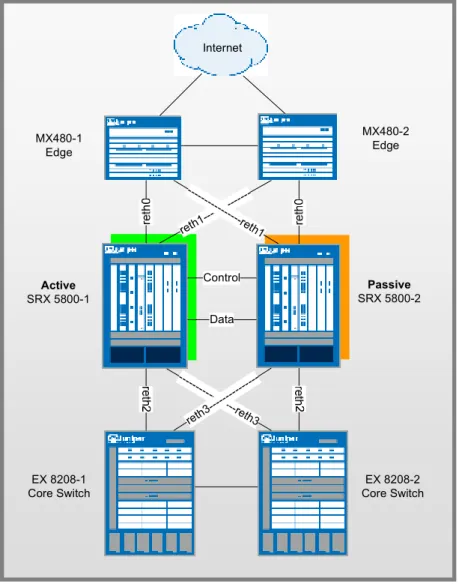
Active / Passive Full Mesh SRX Deployment Scenario
Full Mesh Active/Passive allows the environment to not have a single point of failure in the network not only on the SRX firewalls but also on the surrounding network devices. The main difference between this deployment and the basic deployment is that there are some additional design considerations that must be thought out to accommodate the recovery of possible failure scenarios.
App Note
Active
SRX 5800-1
Passive
SRX 5800-2 Internet
reth1 ---
--- ---
---reth1
Control
Data MX480-1
Edge
MX480-2 Edge
--- -----re
th3 reth3
--- ---
---EX 8208-1 Core Switch
EX 8208-2 Core Switch
Figure 2: Active/Passive Layer 3
Networking Configuration
SRX 5800’s • reth0
o Zone / IP Address: Untrust Zone - 1.1.1.1/24
o SRX 5800-1 Member Interface: xe-6/0/0
o SRX 5800-2 Member Interface: xe-18/0/0 • reth1
o Zone / IP Address: Untrust Zone – 2.2.2.1/24
App Note
o SRX 5800-2 Member Interface: xe-18/1/0 • reth2
o Zone / IP Address: Trust Zone – 3.3.3.1/24
o SRX 5800-1 Member Interface: xe-6/2/0
o SRX 5800-2 Member Interface: xe-18/2/0 • reth3
o Zone / IP Address: Trust Zone – 4.4.4.1/24
o SRX 5800-1 Member Interface: xe-6/3/0
o SRX 5800-2 Member Interface: xe-18/3/0 • High Availability Interfaces
o Control Port:
Node0: FPC 1 port 0 Node1: FPC 13 port 0
o Data/Fabric Port:
Node 0: ge-11/3/0 Node 1: ge-23/3/0
MX 480’s EX 8208’s
• 8208-1
o VLAN / IP Address: Interface VLAN.50 / IP Address 2.2.2.254/24
o VLAN / IP Address: Interface VLAN.60 / IP Address 1.1.1.254/24
o Member Interfaces: xe-1/0/0, xe-2/0/0 (trunk xe-3/0/0) • 8208-2
o VLAN / IP Address: Interface VLAN.50 / IP Address 2.2.2.250/24
o VLAN / IP Address: Interface VLAN.60 / IP Address 1.1.1.250/24
o Member Interfaces: xe-1/0/0, xe-2/0/0 (trunk xe-3/0/0)
SRX Configurations:
Chassis Cluster Configuration
We begin the configuration with the common task of configuring the cluster members to join the cluster. We are going to assume that we are running JUNOS 9.6 for this example on both cluster members, and that they have identical hardware in each chassis. Since we only have a single cluster on the segments, we will just use cluster-id 1, with the SRX 5800-1 being node 0, 5800-2 being node 1. These commands are the only commands where it matters which chassis member you apply them to because the setting is stored in the NVRAM rather than in the configuration itself. The command will
App Note
also cause the cluster member to reboot, which is required at for current versions of JUNOS. Please note that you must issue this command as an operational command, and NOT in configuration mode. The commands that we need to configure are as follows:
SRX 5800-1: set chassis cluster cluster-id 1 node 0 reboot SRX 5800-2: set chassis cluster cluster-id 1 node 1 reboot
*Note if you have multiple SRX clusters on a single L3 broadcast domain, then you much make sure to assign different cluster ID’s to each cluster, or else there will be a MAC address conflict.
Control Port Configuration
Once the chassis members have rebooted, we will now configure the control ports of the clusters. Note that we choose FPC 1 / 13 because the CP is always going to be on the lowest SPC/SPU in the cluster, which in this case is in Slot 0. For maximum reliability, it is recommended to put the Control Ports on a separate SPC from the CP, which is why we choose SPC in Slot 1. As mentioned, all commands going forward are applied on the control plane regardless of which member is active. As of 9.6, this is only required for the SRX 5k platforms, and not the 3k since they used a fixed control port.
set chassis cluster control-ports fpc 1 port 0 set chassis cluster control-ports fpc 13 port 0
Data Fabric Configuration
Now that the control ports are assigned, we must configure the fabric (data) ports of the cluster. These are used to pass RTO’s in Active/Passive mode. Since we are just using this for Active/Passive, there is no advantage to use 10GbE ports, since we will never approach that much bandwidth. Instead, we will just use one of our 1GbE ports. We define two fabric interfaces, one on each chassis (which connect together.)
set interfaces fab0 fabric-options member-interfaces ge-11/3/0 set interfaces fab1 fabric-options member-interfaces ge-23/3/0
Node Specific Configuration
Since the SRX cluster configuration is held within a single common configuration, we need a way to assign some elements of the configuration to a specific member only. This is done in JUNOS with the node specific configuration method called groups. The last command uses the node variable to define how the groups are applied to the nodes (each node will recognize their number and accept the configuration accordingly.) We also configure out of band management on the fxp0 interface of the SRX with separate IP addresses for the individual control planes of the cluster.
set groups node0 set groups node1
set groups node0 system host-name SRX5800-1
set groups node0 interfaces fxp0 unit 0 family inet address 10.3.5.1/24 set groups node0 system backup-router 10.3.5.254 destination 0.0.0.0/0 set groups node1 system host-name SRX5800-2
set groups node1 interfaces fxp0 unit 0 family inet address 10.3.5.2/24 set groups node1 system backup-router 10.3.5.254 destination 0.0.0.0/0
App Note
set apply-groups ${node}
Redundancy Group Configuration
Redundancy Groups are a concept in JSRP clustering that is similar to a Virtual Security Interface in ScreenOS. Basically, each node will have a interface in this group, where only 1 interface will be active at a time. A Redundancy Group is a concept similar to a Virtual Security Device in ScreenOS. Redundancy Group 0 is always for the control plane, while redundancy group 1+ is always for the data plane ports. Since we are running Active/Passive with 4 RETH interfaces, we will assign Redundancy Groups 0 and 1. All 4 RETH interfaces will be members of Redundancy Group 1. We must also configure how many redundant Ethernet groups we will have active on the device (so that they system can allocate the appropriate resources for it. This is similar to Aggregate Ethernet.
We will also need to define which device has priority (in JSRP high priority is preferred) for the control plane, as well as which device is preferred to be active for the data plane. Remember that the control plane can be active on a different chassis than the data plane in active passive (there isn’t anything wrong with this from a technical standpoint, but many administrators probably feel better having both the control and data-plane active on the same chassis member.
set chassis cluster reth-count 4
set chassis cluster redundancy-group 0 node 0 priority 129 set chassis cluster redundancy-group 0 node 1 priority 128 set chassis cluster redundancy-group 1 node 0 priority 129 set chassis cluster redundancy-group 1 node 1 priority 128
Redundant Ethernet Configuration
We now move on to define the actual data interfaces on the platform so that in the event of a data-plane failover, the other chassis member will be able to take over the connection seamlessly. This configuration involves defining the membership information of the member interfaces to the RETH interface, defining which redundancy group the RETH interface will be a member of (in Active/Passive it will always be 1,) and finally defining the RETH interface information such as the IP Address of the interface. Note that local interfaces are not configured as redundant Ethernet members, but as shown in the next step, just as local interfaces that are not members of redundant Ethernet links.
set interfaces xe-6/0/0 gigether-options redundant-parent reth0 set interfaces xe-6/1/0 gigether-options redundant-parent reth1 set interfaces xe-6/2/0 gigether-options redundant-parent reth2 set interfaces xe-6/3/0 gigether-options redundant-parent reth3 set interfaces xe-18/0/0 gigether-options redundant-parent reth0 set interfaces xe-18/1/0 gigether-options redundant-parent reth1 set interfaces xe-18/2/0 gigether-options redundant-parent reth2 set interfaces xe-18/3/0 gigether-options redundant-parent reth3 set interfaces reth0 redundant-ether-options redundancy-group 1 set interfaces reth0 unit 0 family inet address 1.1.1.1/24 set interfaces reth1 redundant-ether-options redundancy-group 1 set interfaces reth1 unit 0 family inet address 2.2.2.1/24
App Note
set interfaces reth2 redundant-ether-options redundancy-group 1 set interfaces reth2 unit 0 family inet address 3.3.3.1/24 set interfaces reth3 redundant-ether-options redundancy-group 1 set interfaces reth3 unit 0 family inet address 4.4.4.1/24
Chassis and Interface Monitoring
Now that we have defined our cluster we want to configure how the cluster should behave in failures. You can see the SRX FAQ for a detailed explanation of failure events and how they impact the state of the chassis. Remember that in SRX, the failover threshold is set a 255, while the weights can be altered to determine the impact on chassis failover. We will also configure control link recovery which automatically causes the secondary node to reboot should the control link fail, then come back up. If this feature is not enabled, then a manual reboot must be performed to bring the secondary node back into sync with the primary. This step is the final step as it relates to the chassis cluster configuration.
set chassis cluster redundancy-group 1 interface-monitor xe-6/0/0 weight 255 set chassis cluster redundancy-group 1 interface-monitor xe-6/1/0 weight 255 set chassis cluster redundancy-group 1 interface-monitor xe-6/2/0 weight 255 set chassis cluster redundancy-group 1 interface-monitor xe-6/3/0 weight 255 set chassis cluster redundancy-group 1 interface-monitor xe-18/0/0 weight 255 set chassis cluster redundancy-group 1 interface-monitor xe-18/1/0 weight 255 set chassis cluster redundancy-group 1 interface-monitor xe-18/2/0 weight 255 set chassis cluster redundancy-group 1 interface-monitor xe-18/3/0 weight 255 set chassis cluster control-link-recovery
*Note that today we cannot monitor individual VLAN’s on an interface only the interface as a whole.
Zone and Virtual Router Configuration
Now that the chassis cluster configuration is complete, the rest of the configuration pretty much follows the exact same configuration as a standalone SRX deployment. We must tie the RETH interfaces to the appropriate zones and virtual routers. Note that the rest of the configuration will essentially reference the RETH interfaces where applicable, rather than the individual member interfaces (similar to how Aggregate Ethernet in JUNOS is configured.) For this example, we are simply going to leave the RETH0 and RETH1 interfaces in the default virtual router inet.0, which does not require any additional configuration.
set security zones security-zone untrust interfaces reth0.0 set security zones security-zone untrust interfaces reth1.0 set security zones security-zone trust interfaces reth2.0 set security zones security-zone trust interfaces reth3.0
App Note
For this example we are going to define a static default route as a backup in the event that the BGP peers fail but not the interfaces themselves, along with the BGP configuration.
set protocols ospf area 0.0.0.0 interface reth0.0 set protocols ospf area 0.0.0.0 interface reth1.0 set protocols ospf area 0.0.0.0 interface reth2.0 set protocols ospf area 0.0.0.0 interface reth3.0 set routing-options graceful-restart
EX-8208 Configuration
For the EX-8208 we are only going to outline the applicable area’s of the configuration as it pertains to this design, notably the VLAN’s, routing, and interface configuration:
EX-8208-1
set interfaces xe-1/0/0 unit 0 family ethernet-switching port-mode access vlan members SRX5800-RETH0
set interfaces xe-2/0/0 unit 0 family ethernet-switching port-mode access vlan members SRX5800-RETH1
set interfaces xe-3/0/0 unit 0 family ethernet-switching port-mode trunk vlan members [SRX5800-RETH1 SRX5800-RETH0]
set interfaces vlan unit 50 family inet address 3.3.3.254/24 set interfaces vlan unit 60 family inet address 4.4.4.254/24 set vlans SRX5800-RETH0 vlan-id 50
set vlans SRX5800-RETH0 l3-interface vlan.50 set vlans SRX5800-RETH1 vlan-id 60
set vlans SRX5800-RETH1 l3-interface vlan.60
set protocols ospf area 0.0.0.0 interface vlan.50 set protocols ospf area 0.0.0.0 interface vlan.60 set routing-options graceful-restart
set protocols rstp interface all
EX-8208-2
set interfaces xe-1/0/0 unit 0 family ethernet-switching port-mode access vlan members SRX5800-RETH0
set interfaces xe-2/0/0 unit 0 family ethernet-switching port-mode access vlan members SRX5800-RETH1
App Note
set interfaces xe-3/0/0 unit 0 family ethernet-switching port-mode trunk vlan members [SRX5800-RETH1 SRX5800-RETH0]
set interfaces vlan unit 50 family inet address 3.3.3.250/24 set interfaces vlan unit 60 family inet address 4.4.4.250/24 set vlans SRX5800-RETH0 vlan-id 50
set vlans SRX5800-RETH0 l3-interface vlan.50 set vlans SRX5800-RETH1 vlan-id 60
set vlans SRX5800-RETH1 l3-interface vlan.60 set protocols ospf area 0.0.0.0 interface vlan.50 set protocols ospf area 0.0.0.0 interface vlan.60 set routing-options graceful-restart
set protocols rstp interface all
MX480 Configuration
The MX is going to follow a similar convention from a configuration perspective, but the configuration of the MX switch is going to be slightly different than EX do to the configuration differences. We will need to use an IRB interface within a virtual switch instance on the switch.
MX480-1
set interfaces xe-1/0/0 encapsulation ethernet-bridge unit 0 family bridge set interfaces xe-2/0/0 encapsulation ethernet-bridge unit 0 family bridge set interfaces xe-3/0/0 encapsulation ethernet-bridge unit 0 family bridge set interfaces xe-4/0/0 encapsulation ethernet-bridge unit 0 family bridge
set interfaces xe-5/0/0 unit 0 family bridge interface-mode trunk vlan-id-list [x y] set interfaces irb unit 0 family inet address 1.1.1.254/24
set interfaces irb unit 1 family inet address 2.2.2.254/24
set routing-options static route 0.0.0.0/0 next-hop (upstream router) set bridge-domains SRX5800-1 vlan-id X
set bridge-domains SRX5800-1 domain-type bridge routing-interface irb.0 set bridge-domains SRX5800-1 domain-type bridge interface xe-1/0/0 set bridge-domains SRX5800-1 domain-type bridge interface xe-2/0/0 set bridge-domains SRX5800-2 vlan-id Y
set bridge-domains SRX5800-2 domain-type bridge routing-interface irb.1 set bridge-domains SRX5800-2 domain-type bridge interface xe-3/0/0 set bridge-domains SRX5800-2 domain-type bridge interface xe-4/0/0
App Note
set protocols ospf area 0.0.0.0 interface irb.0 set protocols ospf area 0.0.0.0 interface irb.1 set routing-options graceful-restart
MX480-2
set interfaces xe-1/0/0 encapsulation ethernet-bridge unit 0 family bridge set interfaces xe-2/0/0 encapsulation ethernet-bridge unit 0 family bridge set interfaces xe-3/0/0 encapsulation ethernet-bridge unit 0 family bridge set interfaces xe-4/0/0 encapsulation ethernet-bridge unit 0 family bridge
set interfaces xe-5/0/0 unit 0 family bridge interface-mode trunk vlan-id-list [x y] set interfaces irb unit 0 family inet address 1.1.1.250/24
set interfaces irb unit 1 family inet address 2.2.2.250/24
set routing-options static route 0.0.0.0/0 next-hop (upstream router) set bridge-domains SRX5800-1 vlan-id X
set bridge-domains SRX5800-1 domain-type bridge routing-interface irb.0 set bridge-domains SRX5800-1 domain-type bridge interface xe-1/0/0 set bridge-domains SRX5800-1 domain-type bridge interface xe-2/0/0 set bridge-domains SRX5800-2 vlan-id Y
set bridge-domains SRX5800-2 domain-type bridge routing-interface irb.1 set bridge-domains SRX5800-2 domain-type bridge interface xe-3/0/0 set bridge-domains SRX5800-2 domain-type bridge interface xe-4/0/0 set protocols ospf area 0.0.0.0 interface irb.0
set protocols ospf area 0.0.0.0 interface irb.1 set routing-options graceful-restart
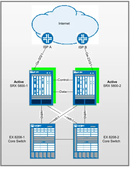
Active / Active SRX Deployment Scenario
The SRX supports Active/Active high availability mode for environments that wish to maintain traffic on both
chassis cluster members whenever possible. In the SRX Active/Active deployment, only the dataplane is in
Active/Active, while the control plane is actually in Active/Passive. This allows 1 control plane to control both
chassis members as a single logical device, and in case of control plane failure, the control plane can fail over to
the other unit. This also means that the data plane can failover independently of the control plane.
Active/Active also allows for ingress interfaces to be on one cluster member, with the egress interface on the
other. When this happens, the data traffic must pass through the data fabric to go to the other cluster member
and out the egress interface (known as Z mode.) Active/Active also allows the ability to have local interfaces
on individual cluster members that are not shared among the cluster in failover, but rather only exist on a single
App Note
chassis. These are often used in conjunction with dynamic routing protocols which will fail traffic over to the
other cluster member if needed.
Active
SRX 5800-1
Active
SRX 5800-2 Internet
Control
Data
---
---reth1 reth1
--- ---
---EX 8208-1 Core Switch
EX 8208-2 Core Switch
ISP A ISP B
Figure 3: Active/Active Layer 3 Networking Configuration
SRX 5800’s (AS 65111) • reth0
o Zone / IP Address: Trust Zone - 1.1.1.1/24
o SRX 5800-1 Member Interface: xe-6/0/0
o SRX 5800-2 Member Interface: xe-18/0/0 • reth1
App Note
o SRX 5800-1 Member Interface: xe-6/1/0
o SRX 5800-2 Member Interface: xe-18/1/0 • Local Interfaces
o SRX 5800-1: xe-6/2/0: Zone/IP Address: Untrust / 3.3.3.1/24
o SRX 5800-2: xe-18/2/0: Zone/IP Address: Untrust / 4.4.4.1/24 • High Availability Interfaces
o Control Port:
Node0: FPC 1 port 0 Node1: FPC 13 port 0
o Data/Fabric Port:
Node 0: xe-6/3/0 Node 1: xe-18/3/0 Internet Peers
• ISP A
o IP Address: 3.3.3.254/24
o BGP AS Number: 65333 • ISP B
o IP Address: 4.4.4.254/24
o BGP AS Number: 65444 EX 8208’s
• 8208-1
o VLAN / IP Address: Interface VLAN.50 / IP Address 2.2.2.254/24
o VLAN / IP Address: Interface VLAN.60 / IP Address 1.1.1.254/24
o Member Interfaces: xe-1/0/0, xe-2/0/0 (trunk xe-3/0/0) • 8208-2
o VLAN / IP Address: Interface VLAN.50 / IP Address 2.2.2.250/24
o VLAN / IP Address: Interface VLAN.60 / IP Address 1.1.1.250/24
o Member Interfaces: xe-1/0/0, xe-2/0/0 (trunk xe-3/0/0)
SRX Configurations:
Chassis Cluster Configuration
We begin the configuration with the common task of configuring the cluster members to join the cluster. We are going to assume that we are running JUNOS 9.6 for this example on both cluster members, and that they have identical hardware in each chassis. Since we only have a single cluster on the segments, we will just use cluster-id 1, with the SRX 5800-1 being node 0, 5800-2 being node 1. These commands are the only commands where it matters which chassis member you apply them to because the setting is stored in the NVRAM rather than in the configuration itself. The command will
App Note
also cause the cluster member to reboot, which is required at for current versions of JUNOS. Please note that you must issue this command as an operational command, and NOT in configuration mode. The commands that we need to configure are as follows:
SRX 5800-1: set chassis cluster cluster-id 1 node 0 reboot SRX 5800-2: set chassis cluster cluster-id 1 node 1 reboot
*Note if you have multiple SRX clusters on a single L3 broadcast domain, then you much make sure to assign different cluster ID’s to each cluster, or else there will be a MAC address conflict.
Control Port Configuration
Once the chassis members have rebooted, we will now configure the control ports of the clusters. Note that we choose FPC 1 / 13 because the CP is always going to be on the lowest SPC/SPU in the cluster, which in this case is in Slot 0. For maximum reliability, it is recommended to put the Control Ports on a separate SPC from the CP, which is why we choose SPC in Slot 1. As mentioned, all commands going forward are applied on the control plane regardless of which member is active. As of 9.6, this is only required for the SRX 5k platforms, and not the 3k since they used a fixed control port.
set chassis cluster control-ports fpc 1 port 0 set chassis cluster control-ports fpc 13 port 0
Data Fabric Configuration
Now that the control ports are assigned, we must configure the fabric (data) ports of the cluster. These are used to pass RTO’s in Active/Passive mode. Since we are using Active/Active, we want to use the 10GbE connection as the data fabric in the event traffic arrives on an ingress interface on one node, and leaves on another. While 1GbE will also work, it is not recommended for A/A deployments. We define two fabric interfaces, one on each chassis (which connect
together.)
set interfaces fab0 fabric-options member-interfaces xe-6/3/0 set interfaces fab1 fabric-options member-interfaces xe-18/3/0 Node Specific Configuration
Since the SRX cluster configuration is held within a single common configuration, we need a way to assign some elements of the configuration to a specific member only. This is done in JUNOS with the node specific configuration method called groups. The last command uses the node variable to define how the groups are applied to the nodes (each node will recognize their number and accept the configuration accordingly.) We also configure out of band management on the fxp0 interface of the SRX with separate IP addresses for the individual control planes of the cluster.
set groups node0 set groups node1
set groups node0 system host-name SRX5800-1
set groups node0 interfaces fxp0 unit 0 family inet address 10.3.5.1/24 set groups node0 system backup-router 10.3.5.254 destination 0.0.0.0/0 set groups node1 system host-name SRX5800-2
set groups node1 interfaces fxp0 unit 0 family inet address 10.3.5.2/24 set groups node1 system backup-router 10.3.5.254 destination 0.0.0.0/0
App Note
set apply-groups ${node}
Redundancy Group Configuration
Redundancy Groups are a concept in JSRP clustering that is similar to a Virtual Security Interface in ScreenOS. Basically, each node will have an interface in this group, where only 1 interface will be active at a time. A Redundancy Group is a concept similar to a Virtual Security Device in ScreenOS. Redundancy Group 0 is always for the control plane, while redundancy group 1+ is always for the data plane ports. Since we are running Active/Active with 2 RETH interfaces, we will assign Redundancy Groups 0, 1, and 2. We must also configure how many redundant Ethernet groups we will have active on the device (so that they system can allocate the appropriate resources for it. This is similar to Aggregate Ethernet.
We will also need to define which device has priority (in JSRP high priority is preferred) for the control plane, as well as which device is preferred to be active for the data plane. Remember that the control plane can be active on a different chassis than the data plane in active passive (there isn’t anything wrong with this from a technical standpoint, but many administrators probably feel better having both the control and data-plane active on the same chassis member. Note that Redundancy Group 0 and 1 will default to being active on Node 0, while Redundancy Group 2 will default to being active on Node 1.
set chassis cluster reth-count 2
set chassis cluster redundancy-group 0 node 0 priority 129 set chassis cluster redundancy-group 0 node 1 priority 128 set chassis cluster redundancy-group 1 node 0 priority 129 set chassis cluster redundancy-group 1 node 1 priority 128 set chassis cluster redundancy-group 2 node 0 priority 128 set chassis cluster redundancy-group 2 node 1 priority 129
Redundant Ethernet Configuration
We now move on to define the actual data interfaces on the platform so that in the event of a data-plane failover, the other chassis member will be able to take over the connection seamlessly. This configuration involves defining the membership information of the member interfaces to the RETH interface, defining which redundancy group the RETH interface will be a member of (in Active/Passive it will always be 1,) and finally defining the RETH interface information such as the IP Address of the interface. Note that local interfaces are not configured as redundant Ethernet members, but as shown in the next step, just as local interfaces that are not members of redundant Ethernet links.
set interfaces xe-6/0/0 gigether-options redundant-parent reth0 set interfaces xe-6/1/0 gigether-options redundant-parent reth1 set interfaces xe-18/0/0 gigether-options redundant-parent reth0 set interfaces xe-18/1/0 gigether-options redundant-parent reth1 set interfaces reth0 redundant-ether-options redundancy-group 1 set interfaces reth0 unit 0 family inet address 1.1.1.1/24 set interfaces reth1 redundant-ether-options redundancy-group 2 set interfaces reth1 unit 0 family inet address 2.2.2.1/24
App Note
For interfaces that don’t belong to redundant Ethernet interfaces, we simply use local interfaces. These interfaces will not failover traffic themselves in the event of a failure, but we typically rely on another mechanism to handle that, in this case, we rely on a dynamic routing protocol (BGP) to accommodate the failover of routing to the other peer.
set interface xe-6/2/0 unit 0 family inet address 3.3.3.1/24 set interface xe-18/2/0 unit 0 family inet address 4.4.4.1/24
Chassis and Interface Monitoring
Now that we have defined our cluster we want to configure how the cluster should behave in failures. You can see the SRX FAQ for a detailed explanation of failure events and how they impact the state of the chassis. Remember that in SRX, the failover threshold is set a 255, while the weights can be altered to determine the impact on chassis failover. We will also configure control link recovery which automatically causes the secondary node to reboot should the control link fail, then come back up. If this feature is not enabled, then a manual reboot must be performed to bring the secondary node back into sync with the primary. In this case, we are not monitoring the local interfaces (although we certainly could) because we don’t want the local interfaces to influence failover. In this case, if a failure happens on a local interface, it will automatically failover via routing with BGP. This also means that there is no manual intervention that must take place to allow traffic to cross chassis. If a local interface fails, the routing will direct the appropriate traffic across the chassis. This step is the final step as it relates to the chassis cluster configuration.
set chassis cluster redundancy-group 1 interface-monitor xe-6/0/0 weight 255 set chassis cluster redundancy-group 1 interface-monitor xe-6/1/0 weight 255 set chassis cluster redundancy-group 1 interface-monitor xe-18/0/0 weight 255 set chassis cluster redundancy-group 1 interface-monitor xe-18/1/0 weight 255 set chassis cluster control-link-recovery
*Note that today we cannot monitor individual VLAN’s on an interface only the interface as a whole.
Zone and Virtual Router Configuration
Now that the chassis cluster configuration is complete, the rest of the configuration pretty much follows the exact same configuration as a standalone SRX deployment. We must tie the RETH interfaces to the appropriate zones and virtual routers. Note that the rest of the configuration will essentially reference the RETH interfaces where applicable, rather than the individual member interfaces (similar to how Aggregate Ethernet in JUNOS is configured.) For this example, we are simply going to leave the RETH0 and RETH1 interfaces in the default virtual router inet.0, which does not require any additional configuration. We also define the local interfaces as part of the appropriate zones.
set security zones security-zone trust interfaces reth0.0 set security zones security-zone trust interfaces reth1.0 set security zones security-zone untrust interfaces xe-6/2/0.0 set security zones security-zone untrust interfaces xe-18/2/0.0
App Note
For this example we are going to define a static default route as a backup in the event that the BGP peers fail but not the interfaces themselves, along with the BGP configuration.
set routing-options static route 0.0.0.0/0 next-hop 3.3.3.254 preference 254 set protocol bgp group eBGP type external
set protocol bgp group eBGP neighbor 3.3.3.254 peer-as 65333 set protocol bgp group eBGP neighbor 4.4.4.254 peer-as 65444 set protocols ospf area 0.0.0.0 interface reth0.0
set protocols ospf area 0.0.0.0 interface reth1.0 set routing-options graceful-restart
set routing-options autonomous-system 65111
EX-8208 Configuration
For the EX-8208 we are only going to outline the applicable area’s of the configuration as it pertains to this design, notably the VLAN’s, routing, and interface configuration:
EX-8208-1
set interfaces xe-1/0/0 unit 0 family ethernet-switching port-mode access vlan members SRX5800-RETH0
set interfaces xe-2/0/0 unit 0 family ethernet-switching port-mode access vlan members SRX5800-RETH1
set interfaces xe-3/0/0 unit 0 family ethernet-switching port-mode trunk vlan members [SRX5800-RETH1 SRX5800-RETH0]
set interfaces vlan unit 50 family inet address 2.2.2.254/24 set interfaces vlan unit 60 family inet address 1.1.1.254/24 set vlans SRX5800-RETH0 vlan-id 50
set vlans SRX5800-RETH0 l3-interface vlan.50 set vlans SRX5800-RETH1 vlan-id 60
set vlans SRX5800-RETH1 l3-interface vlan.60 set protocols ospf area 0.0.0.0 interface vlan.50 set protocols ospf area 0.0.0.0 interface vlan.60 set routing-options graceful-restart
set protocols rstp interface all
App Note
set interfaces xe-1/0/0 unit 0 family ethernet-switching port-mode access vlan members SRX5800-RETH0
set interfaces xe-2/0/0 unit 0 family ethernet-switching port-mode access vlan members SRX5800-RETH1
set interfaces xe-3/0/0 unit 0 family ethernet-switching port-mode trunk vlan members [SRX5800-RETH1 SRX5800-RETH0]
set interfaces vlan unit 50 family inet address 2.2.2.250/24 set interfaces vlan unit 60 family inet address 1.1.1.250/24 set vlans SRX5800-RETH0 vlan-id 50
set vlans SRX5800-RETH0 l3-interface vlan.50 set vlans SRX5800-RETH1 vlan-id 60
set vlans SRX5800-RETH1 l3-interface vlan.60 set protocols ospf area 0.0.0.0 interface vlan.50 set protocols ospf area 0.0.0.0 interface vlan.60 set routing-options graceful-restart
set protocols rstp interface all
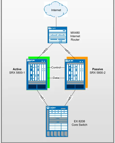
Active / Passive Transparent Mode SRX Deployment Scenario
Transparent Mode allows the SRX platform to operate as a firewall but without requiring the SRX to route traffic. This can be advantageous when an organization needs to drop a firewall into place where IP renumbering is not desired, or where they do not want additional complexity of the firewall participating in a dynamic routing protocol, but rather to filter the traffic itself. The SRX currently only support Active/Passive in Transparent Mode, although Active/Active will be supported in the future. With Active/Passive in Transparent Mode, only a single control and data-plane are active at a time. Unlike Layer 3 mode, we do need to be concerned with bridging loops in the network when running Transparent Mode in HA, but we can rely on Spanning Tree Protocol to ensure that bridging loops do not occur. In this example, we are going to assume that we are using just access-mode links (but an example of the configuration for trunk links is also included) with a single bridging domain. If you wanted to include separate bridging domains you would just configure those accordingly adding them as necessary for separate L2 domains. In this example we are using JUNOS 9.6 because that is the first version that Active/Passive Transparent Mode is supported in. Active/Active Transparent Mode is not yet supported, but will be in the near future, at which point we will add a section for it in this document. Note that other transparent mode options such as bypassing non-ip packets can also be configured the same as it would be in standalone.
App Note
.
Active
SRX 5800-1
Passive
SRX 5800-2 Internet
reth 0 reth
0
Control
Data
MX480 Internet Router
re th1
reth 1
EX 8208 Core Switch
Figure 4: Active/Passive Layer 2 Networking Configuration
SRX 5800’s • reth0
o Zone: Untrust
o SRX 5800-1 Member Interface: xe-6/0/0
o SRX 5800-2 Member Interface: xe-18/0/0 • reth1
o Zone: Trust
o SRX 5800-1 Member Interface: xe-6/1/0
App Note
• High Availability Interfaces
o Control Port:
Node0: FPC 1 port 0 Node1: FPC 13 port 0
o Data/Fabric Port:
Node 0: ge-11/3/0 Node 1: ge-23/3/0
MX 480
• IRB Interface: IP Address 2.2.2.1/24
o Member Interfaces: xe-1/0/0 xe-2/0/0 EX 8208
• VLAN 50 Interface: IP Address 2.2.2.254/24
o Member Interfaces: xe-1/0/0 xe-2/0/0
SRX Configurations:
Chassis Cluster Configuration
We begin the configuration with the common task of configuring the cluster members to join the cluster. We are going to assume that we are running JUNOS 9.6 for this example on both cluster members, and that they have identical hardware in each chassis. Since we only have a single cluster on the segments, we will just use cluster-id 1, with the SRX 5800-1 being node 0, 5800-2 being node 1. These commands are the only commands where it matters which chassis member you apply them to because the setting is stored in the NVRAM rather than in the configuration itself. The command will also cause the cluster member to reboot, which is required at for current versions of JUNOS. Please note that you must issue this command as an operational command, and NOT in configuration mode. The commands that we need to configure are as follows:
SRX 5800-1: set chassis cluster cluster-id 1 node 0 reboot SRX 5800-2: set chassis cluster cluster-id 1 node 1 reboot
*Note if you have multiple SRX clusters on a single L3 broadcast domain, then you much make sure to assign different cluster ID’s to each cluster, or else there will be a MAC address conflict.
App Note
Control Port Configuration
Once the chassis members have rebooted, we will now configure the control ports of the clusters. Note that we choose FPC 1 / 13 because the CP is always going to be on the lowest SPC/SPU in the cluster, which in this case is in Slot 0. For maximum reliability, it is recommended to put the Control Ports on a separate SPC from the CP, which is why we choose SPC in Slot 1. As mentioned, all commands going forward are applied on the control plane regardless of which member is active. As of 9.6, this is only required for the SRX 5k platforms, and not the 3k since they used a fixed control port.
set chassis cluster control-ports fpc 1 port 0 set chassis cluster control-ports fpc 13 port 0
Data Fabric Configuration
Now that the control ports are assigned, we must configure the fabric (data) ports of the cluster. These are used to pass RTO’s in Active/Passive mode. Since we are just using this for Active/Passive, there is no advantage to use 10GbE ports, since we will never approach that much bandwidth. Instead, we will just use one of our 1GbE ports. We define two fabric interfaces, one on each chassis (which connect together.)
set interfaces fab0 fabric-options member-interfaces ge-11/3/0 set interfaces fab1 fabric-options member-interfaces ge-23/3/0
Node Specific Configuration
Since the SRX cluster configuration is held within a single common configuration, we need a way to assign some elements of the configuration to a specific member only. This is done in JUNOS with the node specific configuration method called groups. The last command uses the node variable to define how the groups are applied to the nodes (each node will recognize their number and accept the configuration accordingly.) We also configure out of band management on the fxp0 interface of the SRX with separate IP addresses for the individual control planes of the cluster.
set groups node0 set groups node1
set groups node0 system host-name SRX5800-1
set groups node0 interfaces fxp0 unit 0 family inet address 10.3.5.1/24 set groups node0 system backup-router 10.3.5.254 destination 0.0.0.0/0 set groups node1 system host-name SRX5800-2
set groups node1 interfaces fxp0 unit 0 family inet address 10.3.5.2/24 set groups node1 system backup-router 10.3.5.254 destination 0.0.0.0/0 set apply-groups ${node}
Redundancy Group Configuration
Redundancy Groups are a concept in JSRP clustering that is similar to a Virtual Security Interface in ScreenOS. Basically, each node will have a interface in this group, where only 1 interface will be active at a time. A Redundancy Group is a concept similar to a Virtual Security Device in ScreenOS . Redundancy Group 0 is always for the control plane, while redundancy group 1+ is always for the data plane ports. Since in Active/Passive only 1 chassis member is active at a time, we only define Redundancy Groups 0 and 1. We must also configure how many redundant Ethernet groups we will have active on the device (so that they system can allocate the appropriate resources for it. This is similar to Aggregate Ethernet.
App Note
We will also need to define which device has priority (in JSRP high priority is preferred) for the control plane, as well as which device is preferred to be active for the data plane. Remember that the control plane can be active on a different chassis than the data plane in active passive (there isn’t anything wrong with this from a technical standpoint, but many administrators probably feel better having both the control and data-plane active on the same chassis member.
set chassis cluster reth-count 2
set chassis cluster redundancy-group 0 node 0 priority 129 set chassis cluster redundancy-group 0 node 1 priority 128 set chassis cluster redundancy-group 1 node 0 priority 129 set chassis cluster redundancy-group 1 node 1 priority 128
Redundant Ethernet Configuration
We now move on to define the actual data interfaces on the platform so that in the event of a data-plane failover, the other chassis member will be able to take over the connection seamlessly. This configuration involves defining the membership information of the member interfaces to the RETH interface, defining which redundancy group the RETH interface will be a member of (in Active/Passive it will always be 1,) and finally defining the RETH interface information such as the IP Address of the interface.
Access Mode
set interfaces xe-6/0/0 gigether-options redundant-parent reth0 set interfaces xe-6/1/0 gigether-options redundant-parent reth1 set interfaces xe-18/0/0 gigether-options redundant-parent reth0 set interfaces xe-18/1/0 gigether-options redundant-parent reth1 set interfaces reth0 redundant-ether-options redundancy-group 1 set interfaces reth0 unit 0 family bridge interface-mode access set interfaces reth0 unit 0 family bridge vlan-id 50
set interfaces reth1 redundant-ether-options redundancy-group 1 set interfaces reth1 unit 0 family bridge interface-mode access set interfaces reth1 unit 0 family bridge vlan-id 50
Trunk Mode
We could configure RETH interfaces as trunk interfaces as follows (changes would be required on MX 480 and EX 8200 as well☺
set interfaces xe-6/0/0 gigether-options redundant-parent reth0 set interfaces xe-6/1/0 gigether-options redundant-parent reth1 set interfaces xe-18/0/0 gigether-options redundant-parent reth0 set interfaces xe-18/1/0 gigether-options redundant-parent reth1
App Note
set interfaces reth0 redundant-ether-options redundancy-group 1 set interfaces reth0 vlan-tagging
set interfaces reth0 native-vlan-id 10
set interfaces reth0 unit 0 family bridge interface-mode trunk set interfaces reth0 unit 0 family bridge vlan-id-list 50-60 set interfaces reth1 redundant-ether-options redundancy-group 1 set interfaces reth1 unit 0 family bridge interface-mode trunk set interfaces reth1 unit 0 family bridge vlan-id-list 50-60 set interfaces reth1 vlan-tagging
set interfaces reth1 native-vlan-id 10
Chassis and Interface Monitoring
Now that we have defined our cluster we want to configure how the cluster should behave in failures. You can see the SRX FAQ for a detailed explanation of failure events and how they impact the state of the chassis. Remember that in SRX, the failover threshold is set a 255, while the weights can be altered to determine the impact on chassis failover. We will also configure control link recovery which automatically causes the secondary node to reboot should the control link fail, then come back up. If this feature is not enabled, then a manual reboot must be performed to bring the secondary node back into sync with the primary. This step is the final step as it relates to the chassis cluster configuration.
set chassis cluster redundancy-group 1 interface-monitor xe-6/0/0 weight 255 set chassis cluster redundancy-group 1 interface-monitor xe-6/1/0 weight 255 set chassis cluster redundancy-group 1 interface-monitor xe-18/0/0 weight 255 set chassis cluster redundancy-group 1 interface-monitor xe-18/1/0 weight 255 set chassis cluster control-link-recovery
*Note that today we cannot monitor individual VLAN’s on an interface only the interface as a whole.
Zone and Virtual Router Configuration
Now that the chassis cluster configuration is complete, the rest of the configuration pretty much follows the exact same configuration as a standalone SRX deployment. We must tie the RETH interfaces to the appropriate zones and virtual routers. Note that the rest of the configuration will essentially reference the RETH interfaces where applicable, rather than the individual member interfaces (similar to how Aggregate Ethernet in JUNOS is configured.) For this example, we are simply going to leave the RETH0 and RETH1 interfaces in the default virtual router inet.0, which does not require any additional configuration.
set security zones security-zone untrust interfaces reth0.0 set security zones security-zone trust interfaces reth1.0
App Note
For the EX-8208 we are only going to outline the applicable area’s of the configuration as it pertains to this design, notably the VLAN’s, routing, and interface configuration:
set interfaces xe-1/0/0 unit 0 family ethernet-switching port-mode access vlan members SRX5800
set interfaces xe-2/0/0 unit 0 family ethernet-switching port-mode access vlan members SRX5800
set interfaces vlan unit 50 family inet address 2.2.2.254/24 set vlans SRX5800 vlan-id 50
set vlans SRX5800 l3-interface vlan.50
set routing-options static route 0.0.0.0/0 next-hop 2.2.2.1/24
MX480 Configuration
The MX is going to follow a similar convention from a configuration perspective, but the configuration of the MX switch is going to be slightly different than EX do to the configuration differences. We will need to use a IRB interface within a virtual switch instance on the switch.
set interfaces xe-1/0/0 encapsulation ethernet-bridge unit 0 family bridge set interfaces xe-2/0/0 encapsulation ethernet-bridge unit 0 family bridge set interfaces irb unit 0 family inet address 2.2.2.1/24
set routing-options static route 2.0.0.0/8 next-hop 2.2.2.1
set routing-options static route 0.0.0.0/0 next-hop (upstream router) set bridge-domains SRX5800 vlan-id 50
set bridge-domains SRX5800 domain-type bridge routing-interface irb.0 set bridge-domains SRX5800 domain-type bridge interface xe-1/0/0 set bridge-domains SRX5800 domain-type bridge interface xe-2/0/0
Appendix
Active/Passive Simple SRX Configuration version 9.6B2.7;
groups { node0 { system {
host-name SRX5800-1;
backup-router 10.3.5.254 destination 0.0.0.0/0; }
App Note
fxp0 {
unit 0 {
family inet {
address 10.3.5.1/24; }
} } } }
node1 { system {
host-name SRX5800-2;
backup-router 10.3.5.254 destination 0.0.0.0/0;
}
interfaces { fxp0 {
unit 0 {
family inet {
address 10.3.5.2/24; }
} } } } }
apply-groups "${node}"; system {
root-authentication {
encrypted-password "$1$zTMjraKG$qU8rjxoHzC6Y/WDmYpR9r."; }
name-server { 4.2.2.2; }
App Note
services { ssh {
root-login allow; }
netconf { ssh; }
web-management { http {
interface fxp0.0; }
} } }
chassis { cluster {
control-link-recovery; reth-count 2;
control-ports { fpc 1 port 0; fpc 13 port 0; }
redundancy-group 0 { node 0 priority 129; node 1 priority 128; }
redundancy-group 1 { node 0 priority 129; node 1 priority 128; interface-monitor { xe-6/0/0 weight 255; xe-6/1/0 weight 255; xe-18/0/0 weight 255;
App Note
xe-18/1/0 weight 255; }
} } }
interfaces { xe-6/0/0 {
gigether-options {
redundant-parent reth0; }
}
xe-6/1/0 {
gigether-options {
redundant-parent reth1; }
}
xe-18/0/0 {
gigether-options {
redundant-parent reth0; }
}
xe-18/1/0 {
gigether-options {
redundant-parent reth1; }
} fab0 {
fabric-options {
member-interfaces { ge-11/3/0; }
} } fab1 {
App Note
fabric-options {
member-interfaces { ge-23/3/0; }
} }
reth0 {
redundant-ether-options { redundancy-group 1; }
unit 0 {
family inet {
address 1.1.1.1/24; }
} }
reth1 {
redundant-ether-options { redundancy-group 1; }
unit 0 {
family inet {
address 2.2.2.1/24; }
} } }
routing-options { static {
route 0.0.0.0/0 {
next-hop 1.1.1.254; }
route 2.0.0.0/8 {
App Note
} } }
security { zones {
security-zone trust { host-inbound-traffic { system-services { all;
} }
interfaces { reth0.0; }
}
security-zone untrust { interfaces {
reth1.0; }
} }
policies {
from-zone trust to-zone untrust { policy 1 {
match {
source-address any; destination-address any; application any;
} then { permit; }
App Note
}
default-policy { deny-all; }
} }
Active/Passive Full Mesh Configuration
version 9.6B2.7; groups {
node0 { system {
host-name SRX5800-1;
backup-router 10.3.5.254 destination 0.0.0.0/0;
}
interfaces { fxp0 {
unit 0 {
family inet {
address 10.3.5.1/24; }
} } } }
node1 { system {
host-name SRX5800-2;
backup-router 10.3.5.254 destination 0.0.0.0/0;
}
interfaces { fxp0 {
App Note
unit 0 {
family inet {
address 10.3.5.2/24; }
} } } } }
apply-groups "${node}"; system {
root-authentication {
encrypted-password "$1$zTMjraKG$qU8rjxoHzC6Y/WDmYpR9r."; ## SECRET-DATA }
name-server { 4.2.2.2; }
services { ssh {
root-login allow; }
netconf { ssh; }
web-management { http {
interface fxp0.0; }
} } }
chassis { cluster {
App Note
reth-count 2; control-ports { fpc 1 port 0; fpc 13 port 0; }
redundancy-group 0 { node 0 priority 129; node 1 priority 128; }
redundancy-group 1 { node 0 priority 129; node 1 priority 128; interface-monitor { xe-6/0/0 weight 255; xe-6/1/0 weight 255; xe-18/0/0 weight 255; xe-18/1/0 weight 255; xe-6/2/0 weight 255; xe-6/3/0 weight 255; xe-18/2/0 weight 255; xe-18/3/0 weight 255; }
} } }
interfaces { xe-6/0/0 {
gigether-options {
redundant-parent reth0; }
}
xe-6/1/0 {
gigether-options {
App Note
} }
xe-6/2/0 {
gigether-options {
redundant-parent reth2; }
}
xe-6/3/0 {
gigether-options {
redundant-parent reth3; }
}
xe-18/0/0 {
gigether-options {
redundant-parent reth0; }
}
xe-18/1/0 {
gigether-options {
redundant-parent reth1; }
}
xe-18/2/0 {
gigether-options {
redundant-parent reth2; }
}
xe-18/3/0 {
gigether-options {
redundant-parent reth3; }
} fab0 {
App Note
member-interfaces { ge-11/3/0; }
} } fab1 {
fabric-options {
member-interfaces { ge-23/3/0; }
} }
reth0 {
redundant-ether-options { redundancy-group 1; }
unit 0 {
family inet {
address 1.1.1.1/24; }
} }
reth1 {
redundant-ether-options { redundancy-group 1; }
unit 0 {
family inet {
address 2.2.2.1/24; }
} }
reth2 {
App Note
redundancy-group 1; }
unit 0 {
family inet {
address 3.3.3.1/24; }
} }
reth3 {
redundant-ether-options { redundancy-group 1; }
unit 0 {
family inet {
address 4.4.4.1/24; }
} } }
routing-options { graceful-restart; static {
route 0.0.0.0/0 next-hop 1.1.1.254; route 2.0.0.0/8 next-hop 2.2.2.254; }
}
security { zones {
security-zone trust { host-inbound-traffic { system-services { all;
} }
App Note
interfaces { reth2.0;
reth3.0; } }
security-zone untrust { interfaces {
reth0.0; reth1.0;
} } }
policies {
from-zone trust to-zone untrust { policy 1 {
match {
source-address any; destination-address any; application any;
} then { permit; }
} }
default-policy { deny-all; }
} }
Active/Active Configuration version 9.6B2.7; groups {
App Note
node0 { system {
host-name SRX5800-1;
backup-router 10.3.5.254 destination 0.0.0.0/0; }
interfaces { fxp0 {
unit 0 {
family inet {
address 10.3.5.1/24; }
} } } }
node1 { system {
host-name SRX5800-2;
backup-router 10.3.5.254 destination 0.0.0.0/0; }
interfaces { fxp0 {
unit 0 {
family inet {
address 10.3.5.2/24; }
} } } } }
apply-groups "${node}"; system {
App Note
encrypted-password "$1$zTMjraKG$qU8rjxoHzC6Y/WDmYpR9r."; ## SECRET-DATA }
name-server { 4.2.2.2; }
services { ssh {
root-login allow; }
netconf { ssh; }
web-management { http {
interface fxp0.0; }
} } }
chassis { cluster {
control-link-recovery; reth-count 2;
control-ports { fpc 1 port 0; fpc 13 port 0; }
redundancy-group 0 { node 0 priority 129; node 1 priority 128; }
redundancy-group 1 { node 0 priority 129; node 1 priority 128;
App Note
interface-monitor { xe-6/0/0 weight 255; xe-6/1/0 weight 255; xe-18/0/0 weight 255; xe-18/1/0 weight 255; }
}
redundancy-group 2 { node 0 priority 128; node 1 priority 129; }
} }
interfaces { xe-6/0/0 {
gigether-options {
redundant-parent reth0; }
}
xe-6/1/0 {
gigether-options {
redundant-parent reth1; }
}
xe-6/2/0 { unit 0 {
family inet {
address 3.3.3.1/24; }
} }
xe-18/0/0 {
gigether-options {
App Note
} }
xe-18/1/0 {
gigether-options {
redundant-parent reth1; }
}
xe-18/2/0 { unit 0 {
family inet {
address 4.4.4.1/24; }
} } fab0 {
fabric-options {
member-interfaces { xe-6/3/0;
} } } fab1 {
fabric-options {
member-interfaces { xe-18/3/0; }
} }
reth0 {
redundant-ether-options { redundancy-group 1; }
unit 0 {