Combi B Alarm box
Table of Contents
1 Description ... 3
2 System overview ... 3
3 Structure ... 3
3.1 Power supply ... 3
3.2 Opening monitoring line ... 3
3.3 Tamper line ... 4
3.4 Lock monitoring line via the main bolt contact of the lock ... 4
3.5 Input ... 4
4 Installation ... 5
4.1 Lock monitoring line via the main bolt contact of the lock ... 5
4.2 Silent alarm ... 6
4.3 Input ... 6
5 Technical data ... 7
5.1 Circuit diagram... 8
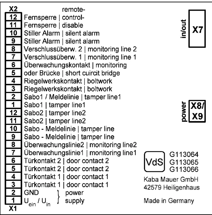
5.2 Connection diagram: ... 9
Illustrations and tables Figure 1: Overall system ... 3
Figure 2: Terminal strip ... 5
Figure 3: Circuit diagram... 8
Figure 4: Connection diagram ... 9
Figure 5: Layout diagram ... 10
1 Description
To integrate the Combi B lock into a VdS-compliant intrusion detection system, the Combi B alarm box must be used. The box allows transmission of a threat alert (silent alarm) and of the status message of the bolt lock to an intrusion detection system. In addition, the operation of the lock can be disabled via an input. Finally, the box allows permanent power supply of the lock if a suitable supply by the IDS or a power pack is in place.
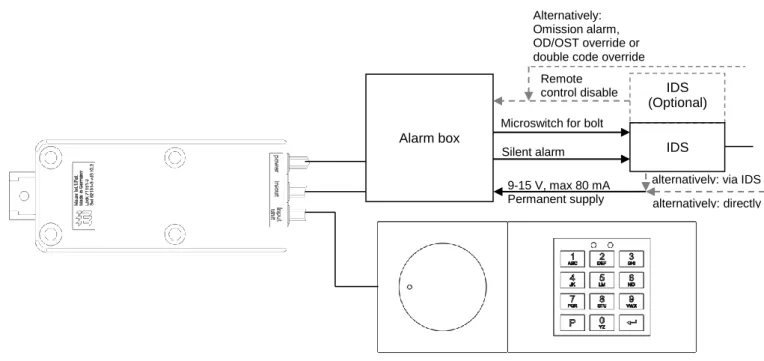
2 System overview
Figure 1: Overall system
3 Structure
The alarm box makes the inputs and outputs of the lock available to an intrusion detection system (IDS) connected downstream. Installation and commissioning should be performed exclusively by authorized skilled personnel. The line resistors to be in-stalled separately are not part of the scope of delivery and must be soldered in in accordance with the specifications of the manufacturer of the alarm technology.
3.1 Power supply
Terminals: X1.1 (plus Uon) and X1.2 (minus Uon, or GND), see Figure 4
The power supply is 12V ±10% Maximum current consumption 80mA
IDS (Optional)
Alarm box
Microswitch for bolt monitoring
Silent alarm IDS
9-15 V, max 80 mA
Permanent supply alternatively: directly alternatively: via IDS Remote
control disable Alternatively: Omission alarm, OD/OST override or double code override
3.3 Tamper line
Terminals: X1.9 to X1.12 and X2.1 and X2.2, see Figure 4 Line resistors, either R102 or R104, see Figure 3
An additional (external optional) tamper device can also be installed in the tamper line.
The cover contact of the alarm box is part of the line. The cover contact is actuated by closing the alarm box.
A connection to the opening monitoring line can also be provided as an option.
3.4 Lock monitoring line via the main bolt contact of the lock Terminals: X2.3 to X2.8, see Figure 4
Line resistors, either R105 or R106, see Figure 3
The main bolt contact of the lock forms part of the lock monitoring line.
By alternative installation of a short-circuit bridge in R107 (see Figure 3), variant A or variant B, the contact can be used as NC or NO contact.
Further possible connections for boltwork contacts or monitoring contacts can be incorporated in the line.
3.5 Input
Terminals: X2.11 (plus Uon) and X2.12 (minus Uon, or GND), see Figure 4
Uon = 12V ± 10% / I = 10mA +20% in as-delivered configuration
Series resistor R110 for variant A or B, as desired / pre-configured for variant A with 1.2kΏ, see Figure 3
The lock has a signal input. This input is inactive ex works. Via the PC software (see PC Software Manual), the input can be configured as remote control disable, omission alarm, override of the opening delay / opening stand-by time or double code override (for details, see Combi B PC Software Manual).
- If the remote control disable signal is active, the lock cannot be opened nor reprogrammed. In this case, each key press at the operating unit of the lock is acknowledged by the red LED flashing once.
Notice: Opening by means of the emergency key is not blocked by the remote control disable.
- An omission alarm is only triggered if prior to the code input no separate signal generator is pressed or no additional authorization is given.
- The override function of the opening delay / opening stand-by time (OD/OST) has the effect that the opening delay time can be skipped when a switch is actuated (see above).
- The double code override functions exactly as the OD/OW override, except that not the opening delay time is skipped, but the set double code is replaced by a simple code when a signal is active.
4 Installation
For installation, all components of the system (lock, input unit and alarm box) must be free of voltage. Please remove all con-nections of the lock and the batteries of the operating unit, if necessary.
The alarm box must be provided with the required line resistors while de-energized. In the delivery state, the terminals X1 and X2 (see Figure 4) to the intrusion detection technology are in the close position.
Figure 2: Terminal strip
To close the spring clamps, the white sliders are pushed toward the cable using a screwdriver (see Figure 2). The connected cable must then be checked for tight fit.
Once the lock has been de-energized, the 8-pin interface cable of the alarm box is plugged into the "IN/OUT" socket at the Combi B lock. The 4-pin power cable of the alarm box is plugged into the "Power" socket at the Combi B lock.
The Combi B alarm box must be supplied with power from an external voltage source. Either the KMH "Combi B alarm box power pack“ (article number 3002501230) or an alternative voltage source of the required specifications 9-15 volts DC, current consumption lock/box max. 80mA must be used, e.g. the supply of an IDS. The power pack or the alternative voltage source is connected to the two terminals X1.1 (Uon) and X1.2 (GND, see Figure 4) of the alarm box. Despite the power supply of the lock
by means of the alarm box ("Power" plug of the lock), the batteries must also be inserted again into the Combi B input unit. Without inserted batteries, a continuous undervoltage display will be shown at the lock (see operating instructions chapter 13.3)!
4.1 Lock monitoring line via the main bolt contact of the lock Terminals: X2.3 to X2.8, see Figure 4
Line resistors, either R105 or R106, see Figure 3
The main bolt contact of the lock forms part of the lock monitoring line. It does not have to be activated, but is always active. If variant A (see Figure 3) has been mounted, the main bolt contact will function as NC contact. However, if variant B (see Fig-ure 3) has been mounted, the contact can be used as NO contact.
Open position
4.2 Silent alarm
Terminals: X2.9 and X2.10, see Figure 4 Line resistor R108, see Figure 3
Short-circuit bridge for variant A or B, as desired, on R107, see Figure 3
When the silent alarm is set at the lock for the first time, the output is switched once for four seconds for checking purposes (for the terminals and resistors, see above).
To check the silent alarm later on in lock operation, an alarm code must entered at the lock. Unlike the actual opening code, the alarm code is entered with +/- 1 at the last digit (for more details on activating and entering an alarm code, please refer to the operating instructions Combi B chapters 9.5 and 10.4). If wired correctly, the appropriate alarm signal should arrive at the con-nected system (e.g. IDS). If this is not the case, the installation (see chapter 4.2) must be checked.
Notice: If a master code has not yet been activated at the lock, but the installer code is still operating, no alarm will be triggered! More details can be found in the operating instructions chapter 8.
Depending on the mounting position of the resistors in the box, the installer configures the silent alarm as NC contact (variant A, see Figure 3) or NO contact (variant B, see Figure 3) at the terminals of the box for the IDS.
4.3 Input
Terminals: X2.11 and X2.12, see Figure 4
Series resistor R108 for variant A or B, as desired, see Figure 3
Depending on which functions are active (inactive ex works, others set via the PC software), the installation must be checked as follows:
Notice: All functions must be checked under all circumstances with the storage unit open.
To check the remote control disable, energizing must be carried out as described in chapter 4.3 and an opening intent must be carried out at the lock (see operating instructions chapters 8 and 10). If you receive a signal from the red LED each time a key is pressed, the disable function works correctly. If you can operate the lock as usual or even open or program it, the remote control disable does not work, and the installation must be checked. With the remote control disable functioning, you must also check whether it can be disabled again and whether the lock can be opened by means of the correct code.
To test the omission alarm, the signal must be triggered (see chapter 4.3), a valid code must be entered at the lock and a check as to whether a silent alarm was triggered must be carried out. This must be followed by entering a valid code without triggering the signal prior to that and checking whether a silent alarm (duration 4 seconds) has now been trig-gered. If this is not the case, the installation and the setting of the lock must be checked by means of the PC software.
To test the override of the opening delay/opening stand-by time, make sure that the opening delay/opening stand-by time at the lock is active (see operating instructions chapter 9.3). Now the signal must be triggered (see chapter 4.3) and a valid code must be entered at the lock. It should be possible to open the lock directly without starting the opening delay. If this is not the case, the installation and the setting of the lock must be checked. If the override is working, check whether the opening delay proceeds as programmed if the signal is not triggered. If the opening delay is not working properly, the opening delay programming of the lock must be checked (see operating instructions chapter 9.3).
To test the double code (DC) override, make sure that the DC is active (see operating instructions chapter 9.4). Now the signal must be triggered (see chapter3.5) and a valid code must be entered at the lock. It should be possible to open the lock directly without expecting the second code. If this is not the case, the installation and the setting of the lock must be checked. If the override is working, check in a second step whether the DC is requested if the signal is not triggered. If no DC is requested, the DC programming of the lock must be checked (see operating instructions chapter 9.4).
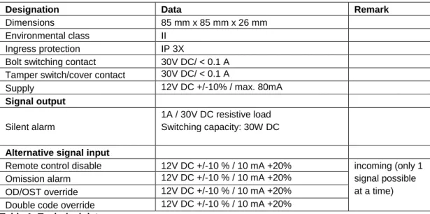
5 Technical data
Designation Data Remark
Dimensions 85 mm x 85 mm x 26 mm
Environmental class II
Ingress protection IP 3X
Bolt switching contact 30V DC/ < 0.1 A Tamper switch/cover contact 30V DC/ < 0.1 A
Supply 12V DC +/-10% / max. 80mA
Signal output Silent alarm
1A / 30V DC resistive load Switching capacity: 30W DC
Alternative signal input
Remote control disable 12V DC +/-10 % / 10 mA +20% incoming (only 1
signal possible at a time)
Omission alarm 12V DC +/-10 % / 10 mA +20%
OD/OST override 12V DC +/-10 % / 10 mA +20%
Double code override 12V DC +/-10 % / 10 mA +20% Table 1: Technical data
5.2 Connection diagram:
X7
X8 X X X
X2 -12 X1
-12
X1 GND 12V DC 9V DC GND
R101 R10R104 R102
C N N
R110 R108 R109 R106 R105 R107