Preserving Architectural Decisions through
Architectural Patterns
Minh Tu Thon That, Salah Sadou, F Oquendo, R Fleurquin
To cite this version:
Minh Tu Thon That, Salah Sadou, F Oquendo, R Fleurquin. Preserving Architectural Decisions
through Architectural Patterns. Journal of Automated Software Engineering, Springer, 2014,
pp.1-41.
<10.1007/s10515-014-0172-0>.
<hal-01102187>
HAL Id: hal-01102187
https://hal.archives-ouvertes.fr/hal-01102187
Submitted on 12 Jan 2015
HAL
is a multi-disciplinary open access
archive for the deposit and dissemination of
sci-entific research documents, whether they are
pub-lished or not.
The documents may come from
teaching and research institutions in France or
abroad, or from public or private research centers.
L’archive ouverte pluridisciplinaire
HAL
, est
destin´
ee au d´
epˆ
ot et `
a la diffusion de documents
scientifiques de niveau recherche, publi´
es ou non,
´
emanant des ´
etablissements d’enseignement et de
recherche fran¸
cais ou ´
etrangers, des laboratoires
publics ou priv´
es.
(will be inserted by the editor)
Preserving Architectural Decisions through
Architectural Patterns
Minh Tu Ton That · Salah Sadou ·
Flavio Oquendo · R´egis Fleurquin
Received: date / Accepted: date
Abstract Architectural decisions have emerged as a means to maintain the quality of the architecture during its evolution. One of the most important de-cisions made by architects are those about the design approach such as the use of patterns or styles in the architecture. The structural nature of this type of decisions give them the potential to be controlled systematically. In the litera-ture, there are some works on the automation of architectural decision violation checking. In this paper we show that these works do not allow to detect all possible architectural decision violations. To solve this problem we propose an approach which: i) describes architectural patterns that hold the architectural decision definition, ii) integrates architectural decisions into an architectural model and, iii) automates the architectural decision conformance checking. The approach is implemented using Eclipse Modeling Framework and its ac-companying technologies. Starting from well-known architectural patterns, we show that we can formalize all those related to the structural aspect. Through two evaluations, we show that our approach can be adapted to different ar-chitecture paradigms and allows to detect more violations comparing to the existing approaches.
Keywords Architectural decision·Pattern·Model Driving Engineering
M.T. Ton That
Universite de Bretagne Sud, IRISA, Vannes, France E-mail: minh-tu.ton-that@irisa.fr
S. Sadou
Universite de Bretagne Sud, IRISA, Vannes, France E-mail: Salah.Sadou@irisa.fr
F. Oquendo
Universite de Bretagne Sud, IRISA, Vannes, France E-mail: Flavio.Oquendo@irisa.fr
R. Fleurquin
Universite de Bretagne Sud, IRISA, Vannes, France E-mail: regis.fleurquin@irisa.fr
1 Introduction
Software architectures deal with the decomposition of a system into its major components, the mechanisms and rules by which these components interact and the global properties of the system that emerge from the composition of its pieces. Documenting software architectures during the development pro-duces major benefits such as early analysis, system visibility and complexity management, design discipline and global conceptual integrity management. During the maintenance, architecture models can help software developers to gain a sufficient knowledge of the software. Thus, these high level models play now a central role in all the stages of the software processes. But to be actually useful such models cannot be confined just to a simple “blueprint” role. They should also provide knowledge about the “reasons” that led to the adoption of this particular architecture. An architecture model should help in pointing and understanding the usage of a particular component, organization, style or pattern. A good software architecture must talk about itself. This self-content attitude is very important particularly during the maintenance. Without it, any evolution of the system becomes potentially time-consuming and risky. In-deed, a change maybe in contradiction with some previously taken decisions, which lead the system to lose some of its properties (such as maintainabil-ity, portability or performance). When the problem is detected, a rework is needed. It is a sequence of iterations, that undoubtedly increases the develop-ment costs. To avoid this problem, we should i) make explicit this knowledge and ii) check (automatically if possible) that a change to be made does not conflict with past decisions.
Usually, the documentation of this knowledge takes the form of a set of what we call anarchitectural decision (AD) [17]. ADs cover many aspects of an architecture. Among these aspects, those related to the structure of the architecture have the highest potential to be automatically checked. This type of AD highlights a particular subset of an architecture model (a subset of the model elements) and conveys itsrationale. For instance, a structural AD can stipulate that a pipeline style is introduced in some part of an architecture to ensure a certain level of maintainability for a specific function. Because the capitalization of structural ADs is a central concern, several proposals have already been made to formally document and check them. Most of these proposals rely on the concept of pattern. This choice is due to the fact that at the architecture level, a typical design decision is about applying some architectural patterns or styles that address the quality requirements of the system [3, 41]. The use of architectural patterns as structural solutions of ADs (called StAD in the remaining of this paper) helps the architect to have a general, high level view about an architecture [43, 45].
There are mainly two trends of proposal in the literature concerning the automatic checking of StAD. The first trend such as [38, 39] focuses on the re-spect of the applied pattern in the architecture model. StADs take the form of architectural constraints describing the organisation imposed by the pattern. These constraints are carried by the impacted model elements. Modifications
or additions to the model that cause a violation of the structure (constraints) of a pattern can be detected. The drawback of using these approaches to doc-ument StADs is that the consistency is only checked as long as concerned elements structurally conform to their playing roles in the architecture. Con-sequently, the existence of pattern-related elements is a condition that is left unchecked which can lead to undetected violations when deletions are done. On the contrary to these mentioned work, the second trend consists of several studies such as [18, 19, 8] which are conducted to define the trace of applying patterns in the architecture. Instead of maintaining the structural consistency of a pattern, these works focus on verifying the existence of the impacted model elements. Deletions of these elements are detected but they can cause, as modifications of these elements, some false positive. Moreover additions that would affect the consistency of a pattern are not detected. It is unsure that the semantics of applied patterns’ structure is assured during the archi-tecture’s evolution. Thus, none of these proposals can ensure that all the StAD violations will be detected.
In this paper we propose an additional support to the documentation of StADs which helps architects to automatically preserve architectural knowl-edge about the structure of architecture. We chose also to use architectural patterns as a support for describing StADs. We make explicit the links between the pattern’s elements and the architecture’s elements through a mapping. Thanks to this mapping, after an evolution, it becomes possible to discover that a StAD is no longer implemented in the architecture, even if all the involved elements from the architecture were removed. Thus, our approach emphasizes the usefulness of combining mapping models and pattern models in documenting StADs. Indeed, mapping models and pattern models together maintain the existence of the StAD and its structural consistency. The ab-sence of one of these two artefacts will lead to an incomplete StAD and thus, undetected violations.
The remaining of the paper is organized as follows. Section 2 introduces the vocabulary and concepts related to ADs and patterns. Section 3 gives an illus-tration of the problem and shows the limitations of the existing approaches. Section 4 introduces the general approach while Section 5 goes into detail of the reusable StAD creation step. Section 6 describes StAD manipulation stage. Section 7 introduces the implemented toolset and Section 8 two validations we have conducted. Before concluding the paper in Section 10, we discuss related work in Section 9.
2 Background
We conducted a review of the relevant literature about AD documentation and pattern modeling and how the latter can be used to support the former. More specifically, we concentrated on ADs about the use of patterns in the architecture. We discuss these issues in the sub-sections below.
2.1 Architectural Decision (AD)
An AD is defined as the description of a set of any modification made to the software architecture together with its rationale, design rules and design constraints [17]. AD is structured by ISO/IEC/IEEE 42010 [16] as a concept that affects architectural description elements, pertains to one or more con-cernsand justifiesarchitectural rationale. Anarchitectural description element
could be a stakeholder, a viewpoint, a model element, etc. A concern could be any interest in the system such as behavior, cost, structure, etc. An ar-chitecture rationale is the explanation, justification or reasoning about the architecture decisions that have been made and architectural alternatives not chosen. This definition comes after many efforts in the literature to draw a complete structure for AD such as [17, 40, 46].
AD documentation serves as a means to emphasize the rationale behind some design decisions having been made. Respecting these rationale means that the architecture evolves in harmony with existing design decisions. Thus, architecture is the result of making a set of ADs, and by documentation the outcomes of those ADs are recorded [9].
2.2 Pattern
A pattern presents a well-proven solution for a particular recurring design problem that arises in a specific design context [6]. Patterns serve many differ-ent purposes. They provide common vocabulary and understanding for design principles. Patterns themselves are a means of documenting software archi-tecture. But most importantly, patterns support the construction of software with well-defined properties [12]. That is the reason why a typical method of software architecture development is to select and combine a number of pat-terns that address the expected quality requirements and use them to build elements of the architecture [3, 5, 41, 35]. Therefore, pattern-centric software architectures are built around the notion of pattern. Such a software architec-ture strucarchitec-ture can be seen to be an amalgamation of many different patterns.
2.3 StAD about the application of patterns
ADs can fall into many different categories: ADs about the applied technol-ogy, the system assets or the conceptual model of the architecture [46]. Among them, structural ADs are the most common ones [30]. Indeed, every evolution of a system often begins with structural ADs taken to modify the structure of architecture since they affect the system on the highest level of abstraction. StAD is a part of structural AD. StAD highlights certain structures in the architecture and links them to structural ADs [31]. It not only conveys the intention of architects but also shapes the structure of the architecture. Thus, a StAD-conformed structure within the architecture not only represents the
intention of an AD but also, in terms of AK (architectural knowledge), is the indicator of the existence of AK. One of the most popular StADs are those concerning the application of patterns in the architecture. Indeed, patterns concern some of the most important AD and provide a rich set of AK [43]. Moreover, reusable design knowledge normally documented in patterns can be adapted to inexpensively document AD in specific context [47]. Thus, StADs about the application of architectural patterns become important artefacts that need to be documented. Applying patterns means applying successive StADs that eventually result in an architecture [9]. In other words, StAD claims the reason for which applied patterns prevail in the structure of archi-tecture.
2.4 Pattern Conformance
Patterns, at the architectural level particularly, have become important con-structs in existing ADLs such as Wright [1], Acme [13] or UML [11]. Patterns allow one to define a domain-specific design vocabulary, together with con-straints on how that vocabulary can be used in constructing an architecture. In these ADLs, patterns are initialized by declaring instances of architectural elements and typing them with pattern elements. An architecture is said to conform to a pattern if there is no conflict between pattern-typed architectural elements with respect to pattern constraints. In Acme and Wright, constraints are written based on first-order predicate logic language and pattern consis-tency is verified by formal specification checkers [1, 13]. In UML, constraints, also known as well-formed rules, are written using OCL (Object Constraint Language)[28] and pattern consistency is referred to the conformance of model against model. For instance, in [11] the authors specify pattern by meta-models which in turn, characterize UML design meta-models. In another work [24], the authors use UML’s stereotype extension mechanism to incorporate other ADL’s features, including the description of architectural styles, which are used to verify the conformity of UML models.
2.5 StAD Conformance
In the structural point of view (skipping informal information such as the con-text, the problem, the rationale, etc.), a StAD is thus considered as any addi-tion, subtracaddi-tion, modification made to the structure of software architecture. An architecture is said to conform to a StAD if all of StAD-related elements prevail in the architecture [18, 19]. This understanding of StAD conformance implies two requirements: i) given an architectural element, one should be able to trace back to the architectural decision which it is based on and ii) the main consequences of an executed StAD, or the changed elements in the model due to that StAD in other words, must be preserved in the architec-tural model. In case of StAD about the application of pattern, StAD-related
elements are in fact those playing roles in the applied pattern. Thus, the StAD conformance implies that the outcome of the application of that pattern must be documented.
3 Illustration and problem
To illustrate the need of maintaining StADs and how existing work cannot re-spond to this need, we take the FRC (Forestry Regulatory Commission) case study which is described in [36]. FRC is dedicated to commercial activities re-lated to the forestry industry. It has been expanded in the past and expects to continue to change which results in costly development. Therefore, SOA (Ser-vice Oriented Architecture) has been opted to help the system respond more quickly to changing requirements. During the transition step to SOA solution, instead of rebuilding existing components, it was considered faster and less ex-pensive to reuse them. It is the case of theFines service and theEvaluations service which want to access to different repositories managed by a legacy component called Data Controller, a standalone Java EJB (Enterprise Java Beans). TheLegacy Wrapper pattern [36] was chosen to handle this situation as illustrated in Figure 1.
Fig. 1 Legacy Wrapper pattern in FRC
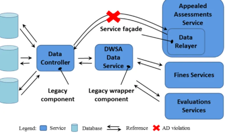
More specifically, the DWSA Data Service which is deployed as a web-service is added to wrap the legacy component Data Controller to assure a seamless communication. The advantage of this pattern is that it allows the Data Controller component to perform changes and refactoring efforts without affecting the other service consumers that bind to it. This pattern im-plies the constraint stipulating that every service can only connect to theData Controller component via the wrapperDWSA Data Service. The application of the Legacy Wrapper pattern in the FRC architecture is a StAD that needs to be taken into consideration throughout the evolution of FRC. In the viewpoint of the existence of related elements, this StAD is considered to be preserved as long as the legacy componentData Controller and the wrapperDWSA Data
Service exist in the architecture of FRC. On the other hand, in the viewpoint of the pattern’s structural consistency, this StAD is maintained as long as the legacy componentData Controller is the only component being able to access to the wrapperDWSA Data Service.
Later, a new service called Appealed Assessments was added to FRC and it also needs to access the Data Controller component. The architect that decided this addition was not completely aware of the rationale behind the existence of the wrapper DWSA Data Service. He then decided to use the Service Fa¸cade pattern [36]. More specifically, a fa¸cade called Data Relayer is added inside the Appealed Assessments Service with the only purpose to communicate with the component Data Controller (Figure 2). The reason influencing the architect not to use the Legacy Wrapper pattern is that Service Fa¸cade is simpler to implement, although the service using a fa¸cade will be coupled to the legacy component.
Fig. 2 Architectural decision violation by adding Service Fa¸cade pattern
As we can observe in Figure 2, the constraint of theLegacy Wrapper pat-tern is violated due to the fact that the Appealed Assessments Service can still connect to theData Controller component via theData Relayer fa¸cade with-out passing through the wrapperDWSA Data Service. In spite of the existence of the legacy componentData Controller and the wrapperDWSA Data Ser-vice, the decision of using Legacy Wrapper pattern has been violated since its structural consistency is not insured. This example shows that the existence of StAD-related elements is a necessary condition but not a sufficient one to detect the violation of StADs. Indeed, one indispensable part of architectural pattern is constraints imposed on future evolution of concerned elements.
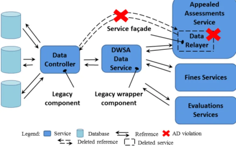
Once informed about the violation, the architect changed the Legacy Wrap-per pattern to a less rigid version which allows fa¸cade components to connect to legacy components. Thus, the link betweenAppealed Assessments Service
par-ticipated in the project. He was not aware of the extended version of the Legacy Wrapper and he found that the Appealed Assessments Service must not access the Data Controller component directly. He deleted the link from theAppealed Assessments Service component towards the legacy component
Data Controller and the Data Relayer fa¸cade as well. Then he added a link between theAppealed Assessments Servicecomponent and the legacy wrapper
DWSA Data Service.
Fig. 3 Architectural decision violation by deletion
Despite that the structural consistency of Legacy Wrapper pattern is al-ways insured (there is no direct access to the legacy component), the decision of allowing theData Relayercomponent (fa¸cade) to access directly to theData Controller component (legacy component) as an extended version of Legacy Wrapper pattern has not been preserved as shown in Figure 3. Thus, the struc-tural consistency of pattern is also a necessary condition but not a sufficient one to detect the violation of StADs. Indeed, the obvious prerequisite of an architecture conformed to a given pattern is that the concerned elements must exist.
In summary, these examples show that the documentation of StADs about the application of patterns should focus on two aspects: the existence of related elements and the structural consistency of the applied patterns. Moreover, they are complementary aspects and both of them must be considered in evaluating StADs. In other words, one aspect can not replace the role of the other one and vice versa. The lack of one of these two aspects could lead to undetected StAD violations. In the literature, the existing work about ADLs [1, 13] or architec-tural constraints [37, 38] focus solely on the strucarchitec-tural consistency aspect. The validity of StADs is maintained as long as concerned elements structurally conform to their playing roles in the architecture. Whereas, the other work about ADs [19, 21, 18] on the other hand, focus on the existence aspect. A
StAD is considered to be preserved as long as modifications to concerned ele-ments persist in the architecture. The approach presented in the remaining of this paper consists in combining these two aspects in documenting StADs.
4 General Approach
The main idea behind our work is that StADs about the use of patterns should be preserved throughout the evolution of the architecture. More specifically, the existence of pattern-related elements and the structural consistency of StADs about pattern use should be automatically checked whenever there is a modification to the architectural model. Because we only concentrate on StADs about pattern use and for the sake of simplicity, the term StAD throughout the following this paper is understood as StAD about pattern use. Moreover, we focus on the structural part of AD to support the conformance checking. It does not mean that the other parts of AD such as the rationale or the concerns are not important. Instead, together they make a complete structure of StADs that supports both the documentation and the automatic checking.
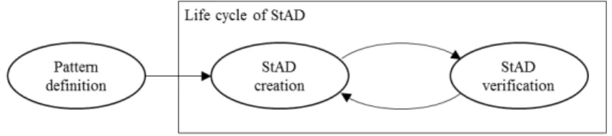
Similar to [46], StAD documentation in our approach goes through three steps: Pattern creation, StAD integration and StAD verification. Figure 4 de-picts the process of using StADs in architecture construction.
Fig. 4 The process of using StAD
Pattern creation consists in the specification of a pattern structure. A pattern is defined once and used for all concerned StADs. StAD creation is the step in which the decision about the application of the defined pattern is created. Finally during theStAD verification step, the architectural model is checked whether it complies with the created StAD. If the architectural model is found to be inconsistent with the created StAD, the architect can come back to theStAD creation step and recreate another StAD and so forth.
On the purpose of automating the process of StAD documentation, we use the Model Driven Architecture (MDA) approach [27]. Each artifact is considered as a model conforming to its meta-model in order to create a sys-tematic process thanks to model transformations and leverage existing MDA techniques (e.g. conformity verification).
In the remainder of this section, we will go further into each step in the StAD documentation process.
4.1 Pattern definition
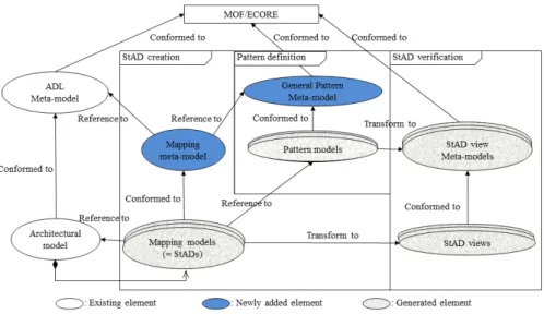
We propose the use of a general pattern language for the purpose of pattern definition. As shown in Figure 5 (Pattern definition part), the abstract syntax of this language is described using ageneral pattern meta-modelwhich contains only architectural elements involved in the pattern definition. These elements are determined through a survey of well-known architectural patterns such as those described in [36, 9, 6]. In terms of concrete syntax of our language, one can graphically define a meaningful architectural pattern in form of a
pattern model using necessary elements. Furthermore,pattern modelsare also language-independent. With the separation between pattern definition and architectural design, no modification to the architectural model is needed to define a pattern, which makes it easy to adapt to different ADLs.
4.2 StAD creation
Links between pattern elements and their correspondent architectural elements play an important role in keeping track of StAD made to an architectural model. An explicit linking will facilitate the specification of StADs as well as their storage. In our approach, links between pattern elements and architec-tural elements are represented bymapping models (illustrated in the Pattern integration part of Figure 5). A mapping model indicates that a StAD has been applied on an architectural model.
In the literature, architecture is considered as a set of views which are representations of system elements and relations associated with them [9]. Each view serves a specific purpose depending on the concerns of one or more stakeholders. Having taken this viewpoint into account, we propose to consider anarchitectural model as a multi-view representation where each view contains only elements related to a specific StAD. In this scenario, StAD views are filtered from thearchitectural model through a transformation mechanism in whichmapping models are the source models andStAD views are the target models. In fact, we can consider the mapping models as the initial version of the StAD views where information about the integration of StAD is stored. Thus, the transformation is the step in which this information are concretized intoStAD views elements.
4.3 StAD verification
To make sure that anarchitectural modelis consistent with created StADs, not only do the existence of StAD-related elements in anarchitectural modelneed to be verified but also the constraints imposed on them need to be handled. To achieve the first goal, the presence of StADs in the architectural model is checked through the completeness ofmapping models. Indeed,mapping models
are intermediary bridges between thearchitectural modeland thepattern model
and thus, the incompleteness ofmapping models shows the lack of StADs in the architectural model. To achieve the second goal, the constraints imposed by patterns on thearchitectural model are checked through the consistence of
StAD views. To check the conformity ofStAD views, we chose to first transform thepattern models into StAD view meta-models (Pattern verification part in figure 5) and then, make use of model checking techniques from MDA [27].
5 Pattern definition
The process of creating a pattern consists in instantiating apattern modelfrom its meta-model. We first introduce thegeneral pattern meta-model from which pattern models are created. Then, we clarify the pattern definition process through a concrete example.
5.1General pattern meta-model
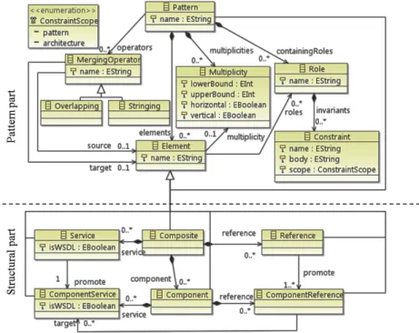
Thegeneral pattern meta-model provides the language to define an architec-tural pattern. It contains all necessary architecarchitec-tural features from the target ADL and concepts related to pattern definition. Figure 6 illustrates two parts of the pattern language: pattern part and structural part. While the pattern part is general enough to be applied in any paradigm, the structural part rep-resents concrete elements for each supported language family. The structural part of one paradigm can be replaced by the structural part of another one.
In this example we choose the structural part that corresponds to SOA de-scription languages family. We provide more details about how to replace the structural part to switch to another language family in Section 8.1.
Fig. 6 SOA General Pattern Meta-model
Inspired by the SCA model1 [4], we construct the structural part of our
General Pattern Meta-Model for the SOA description language family as fol-lows:
– Compositeserves as the container to assemble and connect service-oriented building blocks together.
– Components are basic units of the architecture that represent business functions from which composite applications are built.
– A component is composed ofcomponent servicesandcomponent references. The former provide functionalities supported by the component and the latter play the role of consuming services of other components. A com-ponent reference can be wired to a comcom-ponent service through its target
attribute. The attribute isWSDLspecifies whether the component service is a webservice or not.
1 SCA is a model created by a group of industrial partners to support building applications
– Thinking of composites as black-box components, they have also services
and references. To be consumed by the world outside of a composite, a component service of the containing component can be promoted as a service of the composite. Similarly, to be served by an outside service, a component reference should be promoted as a composite’s reference. Thepattern aspectpart of our meta-model aims at providing functionalities to characterize a meaningful architectural pattern. We reuse the composition-centered pattern description language that we proposed in another work [35]. To be more specific, the meta-model allows us to describe a pattern element at two levels: generic and concrete. Via the multiplicity, we can specify an element as generic or concrete. A concrete element (not associated with any multiplicity) provides guidance on a specific pattern-related feature. Being generic, an element (associated with a multiplicity) represents a set of concrete elements playing the same role in the architecture. A multiplicity indicates
how many times a pattern-related element should be repeated and how it is repeated.
Fig. 7 Orientation organization of generic elements
Figure 7 shows two types of orientation organization for a multiplicity: ver-tical and horizontal. Being organized verver-tically, participating elements are par-allel which means that they are all connected to the same elements, e.g. Clients are all connected to Server in the Client-Server pattern [6]. On the other hand, being organized horizontally, participating elements are inter-connected, e.g. Filters are connected to each other via Pipes in the Pipes and Filters pattern [6]. Each element in the meta-model can be associated with arole. A role spec-ifies properties that a model element must have if it is to be part of a pattern solution model [11]. To characterize a role, we use architectural constraints. A constraint made to a role on an element helps to make sure that the ele-ment participating in a pattern has the aimed characteristics. Constraints are represented in our approach in form of OCL rules. The scope attribute of a constraint helps to determine the affected area of the constraint. If the scope equals pattern, the constraint is imposed only on elements contained in the pattern. Otherwise, the scope equals architecture means that the constraint involves not only elements in the pattern but maybe also other elements in the architecture. Let us take an example of a pattern containing two elements A and B with a constraint saying thatamong all elements connected to element
A, there is only element B assuring certain characteristics. This constraint has anarchitecturescope since it may involve external elements besides those defined in the pattern (A and B) to make sense. This attribute is important to determine pattern-related elements within the architectural model for the purpose of filtering pattern view (see Section 6.2). Patterns in our language can be composed using two operators: overlapping and stringing. A stringing operation means a connector is added to the pattern model to connect one component from one pattern to another component from the other pattern. An overlapping operation means that two involving elements should be merged to a completely new element. Figure 8 shows these two types of merging op-eration.
Fig. 8 Two types of merging operation [35]
The reader can find more information about how to compose patterns using these operators in [35].
5.2 Architectural Pattern Specification
For the purpose of illustration, we will examine the SOA Legacy Wrapper pattern [36] which is also mentioned in Section 3.
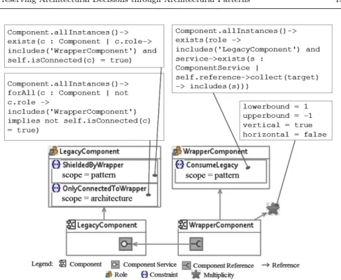
Based on the general pattern meta-model, we can instantiate the pattern model for the SOA Legacy Wrapper with the emphasis on the following ele-ments (as illustrated in Figure 9): the componentLegacyComponent specified with the roleLegacyComponentrepresenting the component with legacy imple-mentations, the componentWrapperComponentspecified with the role Wrap-perComponent representing the wrapper services in the pattern. The compo-nentLegacyComponent is not assigned with any multiplicity since it represents a concrete legacy component. Otherwise, the component WrapperComponent
is assigned with a multiplicity since it represents many possible wrapper com-ponents. Furthermore, its vertical multiplicity2 indicates that there maybe many instances of WrapperComponent and they must be vertically connected. The role LegacyComponent is characterized by the ShieldedByWrapper con-straint and the OnlyConnectedToWrapper constraint. The former stipulates
Fig. 9 SOA Legacy Wrapper pattern model
that there must exist a component that plays the role WrapperComponent
and is connected to the legacy component, the latter stipulates that for all ex-isting components, if one does not play the roleWrapperComponentthen it can not be connected to the legacy component. Note that theShieldedByWrapper
constraint has apatternscope since it involves only elements playing either the roleWrapperComponentorLegacyComponent. TheOnlyConnectedToWrapper
constraint has anarchitecturescope since it involves not only elements playing the two mentioned roles but maybe also other elements in the architecture. The last constraintConsumeLegacy characterizes the roleWrapperComponent
and stipulates that there must exist at least one legacy component with all ser-vices wrapped by the wrapper component. This constraint also has a pattern scope. Even though the other participating elements in the Legacy Wrapper
pattern model, such as the component service of LegacyComponent and the component reference of WrapperComponent, do not have specific roles, they still contribute to the model to make a meaningful pattern.
6 StAD Manipulation
The process of manipulating StADs consists of integrating pattern models to architectural models and checking the conformance of architectural models
with associated StADs. The former is made thanks to a mapping model and the latter is made thanks to a particular view on the architecture.
6.1 Associating a Pattern to an Architectural Model
The association of a pattern with an architectural model consists in manually creating a mapping model between the former and the latter. Concretely, it links elements in the architecture that directly relates to elements from the pattern model. For the sake of simplicity, we do not show the mapping meta-model here but basically, it consists of one meta-class per type of mapping. Each class defines a mapping between the source, an architectural meta-class from the ADL meta-model and the target, an architectural meta-meta-class from thegeneral pattern meta-model. The reader can find this mapping meta-model in Appendix D
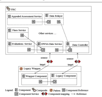
The architecture of FRC case study [36] is chosen to illustrate the documen-tation of pattern use. Figure 10 sketches the mapping model which associates the Legacy Wrapper pattern to a part of the FRC architecture. As we can see in this figure, two components Data Controller and DWSA Data Service in the FRC architecture are mapped respectively to two components playing the roles ofLegacy Component and Wrapper Component in theLegacy Wrapper
pattern model.
An architectural model can contain different mapping models, each of them represents a StAD made to the architecture. Thus, the architectural model can be considered as a set of elements in which each element can play different roles coming from the same StAD or different ones.
6.2 Filtering StAD views
The architectural views are useful for understanding the overall architecture of a complex system. In our case, each view represents one instantiation of a pattern in the architectural model. Thus, a view is produced by applying a transformation on the mapping model which captures a given StAD. The transformation serves as a filter to realize two purposes: first, extract from the architectural model elements related to StADs and second, eliminate language-specific features of the architectural model to create a language-independent pattern view model. This transformation can be compared to the one from PSM (platform specific model) to PIM (platform independent model) in the MDA approach. To realize this, we leverage the MDA transformation tech-niques. More precisely, we use Kermeta [26] transformation rules to transform mapping models into StAD view models.
Algorithm 1 illustrates the transformation of a mapping model into a view model. First, it detects whether the pattern model has an architecture-scope
constraint. If not, the algorithm creates a StAD view model that contains only pattern-related architectural elements. These elements and their pattern
Fig. 10 Mapping model for theLegacy Wrapperpattern in FRC (Elements in dashed line are those added after the evolution of the FRC architecture)
roles are determined via the mapping model. Otherwise, if the pattern model has at least one architecture-scope constraint, then the algorithm creates a StAD view model that contains all elements in the architectural model. But, only the roles related to the concerned pattern are kept in the elements. Pat-terns witharchitecture-scopeconstraints are not usual, as shown through our experimentation on well-known SOA patterns (see section 8.1).
The bottom of Figure 11 represents the filtered StAD view model for the mapping model before (without elements in dashed line) and after (with ele-ments in dashed line) the evolution of the architecture described in Figure 10. As we can recall from the Legacy Wrapper pattern defined in Figure 9, the scope of the constraintOnlyConnectedToWrapperisarchitecture. This leads to the creation of a StAD view that contains all elements in the FRC architecture with only their roles related to theLegacy Wrapper pattern. In the produced StAD view there are two elements holding a role in theLegacyWrapper pat-tern: DWSA Data Service andData Controller playing respectively the two roles WrapperComponent and LegacyComponent. The choice of this illustra-tive pattern is made in order to cover the two kinds of constraint. In general cases architectural patterns hold mainly constraints withpattern-scope. To il-lustrate the StAD views generated in this case, we show on the top of Figure 11 the StAD view for the Legacy Wrapper pattern without taking into account itsarchitecture-scope constraint.
Algorithm 1The StAD view model filtering algorithm Require: MappingModelM M Ensure: StAdViewModelV M 1: PatternModelP M←M M.target 2: ArchitecturalModelAM←M M.source 3: Flagf←f alse
4: for allRoler∈P M.rolesdo
5: for allConstraintc∈r.constraintsdo
6: ifc.scope=architecturethen
7: f←true
8: Break 9: end if
10: end for
11: end for
12: if f =f alsethen //No architecture-scope constraint is found //Only pattern-related elements are filtered
13: for allMappingm∈M M.mappingsdo
14: ArchitecturalElementae←m.source 15: PatternElementpe←m.target 16: StAdViewElementade←ae 17: ade.role←pe.role 18: V M.add(ade) 19: end for
20: else //At least one architecture-scope constraint is found //Filtering all elements
21: for allArchitecturalElementae∈AM.elementsdo
22: StAdViewElementade←ae
23: for allMappingm∈M M.mappingsdo
24: ifm.source=aethen 25: ade.role←m.target.role 26: end if 27: end for 28: V M.add(ade) 29: end for 30: end if 6.3 StAD Checking
The checking process consists of two steps: first, the completeness of the map-ping model is verified and if the mapmap-ping model’s integrity is assured, in the second step, the StAD view meta-model is used to check the consistency of the StAD view model. Whenever the mapping model is detected as incomplete (e.g. due to the removal of some StAD-related elements in the architecture) or constraints imposed by the StAD view meta-models on StAD views are not satisfied, warnings are notified to the architect about which StAD is violated and which elements in the architectural model are involved.
The conformity of an architectural model with its associated StADs is checked through the conformity of the correspondingStAD view with the con-cerned pattern model. For the purpose of checking,StAD view meta-modelsare generated frompattern models. The consistency of anStAD view is thus ver-ified against its corresponding StAD view meta-model using the conformance operator from the MDA approach.
Fig. 11 StAD views for the Legacy Wrapper pattern produced from FRC architecture (Elements in dashed line are those added after the evolution of the FRC architecture)
For every defined pattern model, an StAD view meta-model is generated containing meta-classes from thegeneral pattern meta-model embedded with pattern constraints. The Algorithm 2 represents the simplified version of this transformation.
Algorithm 2The StAD view meta-model creation algorithm
Require: PatternModelM
Ensure: StAdViewMeta-modelM M
1: M M.add(createM etaClasses())
2: for allPatternElementpe∈M.elementsdo
3: Meta-classmc←M M.getCorrespondingM etaClass(pe) //Select the corre-sponding meta-class of the StAD view meta-model based on the pattern model element 4: for allRoler∈pe.rolesdo
5: for allConstraintc∈r.constraintsdo
6: mc.add(c)
7: end for
8: ifpe.getM ultiplicity()6=∅then
9: Multiplicitym←pe.multiplicity
10: mc.add(createM ultiplicityConstraint(m))
11: else //Multiplicity constraint without parameter means that the meta-class should have exactly one instance
12: mc.add(createM ultiplicityConstraint()) 13: end if
14: end for
15: end for
For instance, the Legacy Wrapper pattern model described in the previous section will be transformed to anStAD view meta-model with the
participa-Fig. 12 StAD view meta-model for the Legacy Wrapper pattern.
tion of the following meta-classes:Composite,Service,Reference,Component,
ComponentServiceandComponentReferenceas shown in Figure 12. The StAD view meta-model is embedded with invariants imposed on the Component meta-class as follows: (1) invariant ShieldedByWrapper: if role->includes(’LegacyComponent’) then Component.allInstances()->exists(c: Component | c.role->includes(’WrapperComponent’) and self.isConnected(c) = true) endif; (2) invariant ConsumeLegacy: if role->includes(’WrapperComponent’) then Component.allInstances()->exists(role-> includes(’LegacyComponent’) and service-> exists(s: ComponentService | self.reference-> collect(target)->includes(s))) endif; (3) invariant vertical_WrapperComponent: if role->includes(’WrapperComponent’) then Component.allInstances()->forAll(role-> includes(’WrapperComponent’) implies isParallel(self)) endif; (4) invariant multiplicity_LegacyComponent: let s: Integer = Component.allInstances()->
select(role->includes(’LegacyComponent’))-> size() in s = 1;
(5) invariant multiplicity_WrapperComponent: let s: Integer = Component.allInstances()-> select(role->includes(’WrapperComponent’))-> size() in s >= 1;
(6) invariant OnlyConnectedToWrapper: if role->includes(’LegacyComponent’) then
Component.allInstances()-> forAll(c: Component | not c.role -> includes(’WrapperComponent’) implies not self.isConnected(c) = true) endif;
A part of invariants on meta-classes correspond to the constraints specified on the role elements in the pattern model. The other part reflects information about orientation and multiplicity. We can observe through the example that the constraints imposed on the rolesLegacyComponent and WrapperCompo-nent in the pattern model are transformed into the invariants ShieldedBy-Wrapper (1), OnlyConnectedToWrapper (6) and ConsumeLegacy (2) on the
Componentmeta-class. The multiplicity of the roleWrapperComponentin the pattern model is concretized in two other invariants in theComponent meta-class:multiplicityWrapperComponent(5) andverticalWrapperComponent (3). Since the roleLegacyComponent in the pattern model is not associated with any multiplicity, the invariant multiplicityLegacyComponent (4) restricts the exact number ofLegacyComponent in the pattern view to one.
The FRC architecture passed through an evolution in which two compo-nentsAppealed Assessment ServiceandData Relayer (sketched in dashed line in Figure 10 and Figure 11) are added. As we can observe, its mapping model is complete. However, the addition of the Data Relayer component violates theOnlyConnectedToWrapper constraint (6) since it is directly connected to a component playing the roleLegacyComponent.
Similar to UML, this way of StAD specification allows us to introduce two levels of consistency: meta-model and well-formedness rules. More specifically, well-formedness rules are expressed in OCL to assert the syntactic correctness of StAD view models. According to the classification of model consistency methods presented in [22], this approach is a syntactic-horizontal consistency one.
7 Implementation
To verify the feasibility of our approach, we developed a tool called ADMan-ager, which in its actual version, supports the documentation of StADs in three different languages: SCA [4], Acme [13] and PiADL [29].
Fig. 13 The architecture of ADManager
7.1ADManager tool
WithADManagerwe aim to make concrete the aforementioned concepts. The tool provides the following functionalities:
1. Create architectural patterns
2. Integrate StADs to architectural models
3. Verify the consistency of architectural models according to the held StADs.
ADManageris developed based on EMF (Eclipse Modelling Framework) [32]. We choose EMF to realize our tool since we leverage MDA, where models are basic building units, to develop our approach. As shown in Figure 13, the tool consists of five Eclipse plug-ins built on existing Eclipse technologies. They are:
– Pattern creation plug-in uses EMF and GMF (Graphical Modeling Frame-work)3 modeling support in order to allow architects to define Pattern
models graphically.
– StAD integration plug-in is an editor supporting the creation ofMapping models between pattern elements and architectural model elements.
– StAD verification plug-in uses OCL tool to support writing rules in pat-tern models, during patpat-tern creation, as well as conformance verification between StAD view models and StAD view meta-models during StAD checking.
– StAD view meta-model generator plug-in uses Kermeta to implement rules generating StAD view meta-models from pattern models.
– StAD view generator plug-in uses Kermeta to implement rules generating StAD views from mapping models.
Note that in Figure 6 theGeneral Pattern Meta-Modelfor SOA is separated into two parts: one specific to the SOA description language family and the
other for the notion of pattern. The separation of these two aspects gives our tool the flexibility to support many different ADL families just by switching to the appropriate structural part of the pattern meta-model. Indeed, besides SCA, we have been able to support two different ADLs, namely Acme and PiADL, by keeping the pattern part and modifying the structure part in the pattern meta-model4.
As ADManager is also a consistency management tool, it supports the following functionalities among those described in [10]:
– Automatic inconsistency detection - The tool automatically extracts pat-tern view models from mapping models and checks their consistency.
– Visual inconsistency presentation - The tool provides a visual inconsistency feedback to the user via description dialogues.
– Inconsistency diagnosis - The tool diagnoses a model and presents a user with a summarized report about which pattern is violated and if so, at which constraint.
The reader may obtain a complete guiding tutorial video and more in-formation about the ADManager tool at:http://www-archware.irisa.fr/ software/admanager/.
8 Evaluation
The main contribution which lies behind our work is the documentation of pattern-centric StADs which maintains both the existence of StADs and their structural consistency. For this purpose we defined a general pattern defini-tion language that can be switched from one paradigm to another. Thus, to evaluate our approach, we first show the ability to adapt our pattern defini-tion language in two different paradigms. Then we show the effectiveness of StADs’documentation and their completeness in terms of existence and struc-tural consistency.
8.1 Application of pattern definition language
To evaluate the support of multi-paradigms, we collected patterns from two different paradigms, namely SOA and Component-Based Architecture (CBA), and see how our pattern definition language can support them. There are two criteria upon which patterns are chosen to be formalized. The first one is that the pattern’s vocabulary cannot extend beyond the concepts supported by the corresponding ADL. The second one concerns the scope of the pattern. We limit selected patterns to the structural aspect, other patterns are considered to be out of scope.
8.1.1 SOA patterns
We have examined the SOA patterns from [36] that are summarized in Table 1. In that table we reused the categorization of patterns given in [36]. Among the 80 identified patterns there are up to 50 patterns focusing on the aspect of service management. Examples of service management patterns are those con-cern how to physically centralize or decentralize services, how to determine the boundary of service logic, etc. These patterns in fact do not directly concern the structural aspect of the architecture. Therefore, they cannot be formalized using concepts from the ADL.
Table 1 Categories of SOA Patterns from [36]
Pattern category Patterns Architectural patterns Formalized patterns Patterns with architecture scope constraints Service inventory design patterns 24 10 5 0 Service design patterns 33 14 14 2 Service composition design patterns 23 6 6 2 Total 80 30 25 4
As we can observe in the Table 1, among the remaining 30 architectural patterns there are ones based on architectural concepts that are not supported yet by Service-Oriented ADLs such as service inventory, service layer, etc. This explains why only 25 patterns are formalized using our approach (“Formal-ized patterns” column). Most of the formalizable patterns fall into the Service design pattern category. Indeed, patterns in this category are good practices in service organization, encapsulation, implementation, governance and there-fore, suitable to be architecturally formalized. The column “Patterns with architecture scope constraints” gives the number of patterns holding at least one constraint with architecture-scope. Only 4 patterns, among the 25 formal-izable ones, fall in this case.
8.1.2 CBA patterns
To support the design of CBA patterns, starting from the SOA pattern meta-model (see Section 6), we switched the structural part to another one that conforms to CBA patterns. Figure 14 shows the CBA pattern meta-model. More specifically, this structural part consists of the set of architectural ele-ments: component, connector, port and role. This set of elements is in fact the necessary design vocabulary for architectural pattern as pointed out in [25, 9]. Switching from the SOA pattern meta-model to the CBA pattern meta-model
is in fact the matter of disconnecting the structural part of the former and con-necting the structural part of the latter. More specifically, concon-necting the CBA meta-model to the pattern part consists in i) Adding the inheritance relation-ship between two meta-classes SimpleElement and CompositeElement (CBA part) and the Element meta-class (Pattern part) and ii) Adding a composition relationship between the CompositeElement meta-class (CBA part) and the Element meta-class (Pattern part). Thus, the switching is realized without any modification in the pattern part of the general pattern meta-model.
Fig. 14 General CBA pattern meta-model
Using this adapted pattern language, we have tried to model the CBA pat-tern catalogue described in [2]. Table 2 shows the examined patpat-terns assigned to different viewpoints.
As we can observe, we have been able to model 14 patterns (Column Struc-tural patterns) out of the total 24 patterns (Column Pattern). Our pattern definition language focuses on the structural aspect of architectural patterns. Thus, the patterns concerning the behavioural aspect are not formalized in our study. Representatives of behavioural patterns can be those dealing with invocation mechanism, runtime events, etc. None of the 14 formalized patterns contain a constraint with architecture scope.
The reader can find a complete list of formalized patterns in two paradigms SOA and CBA in Appendix A and Appendix B.
Table 2 Categories of architectural patterns from [2]
Architectural view Pattern Structural pattern
Pattern with architecture scope
constraints Layered view 2 2 0 Data flow view 2 1 0
Data-centered view 3 3 0 Adaptation view 3 2 0 Language extension view 3 0 0 User interaction view 3 3 0 Component interaction view 5 2 0 Distribution view 3 1 0 Total 24 14 0 8.2 StAD documentation
The following subsections discuss the effectiveness and the completeness of our support for StAD documentation. We first introduce the materials used in our study and then go into details of evaluation results.
8.2.1 Evaluation materials
We evaluated our approach with 8 architectural models. These models vary in terms of size and domain. They are gathered from different sources in the literature. These models as well as the evaluation results can be found in a technical report entitled IRISAArchWare-2013-TR-025at ADManager’s web-site. We choose Acme as the ADL to depict these models in this evaluation but as we stated in section 7.1, it is feasible to change to another ADL since the pattern meta-model is language independent. In Acme, an architecture is described using elements such ascomponent, connector, port, role, representa-tion, attachment, etc.among which components and connectors play the most crucial roles. Thus, the size of model is expressed according to three types of measurements: first, by the number of all elements, second, the number of components and third, the number of connectors. Figure 15 shows the sizes of the models in terms of model elements, components and connectors. They differ from small models (49 elements, 7 components and 6 connectors) to big models (287 elements, 34 components and 36 connectors). The models cover different domains, from source code management systems, digital publishing systems to software product line middlewares, etc. The reader can find the list
of architectural models together with applied patterns and their frequency of usage in Appendix C.
Fig. 15 Size of 8 Acme architectural models in terms of model elements, components and connectors
One important criterion in choosing these models is that they must fo-cus on the application of architectural patterns in their design. All of the chosen models are indeed designed using architectural patterns from different paradigms such as Enterprise Integration, SOA, etc. On average, there are two patterns applied per model.
8.2.2 Modeling effort and StAD violation detection
We present in this section a quantitative evaluation on the modeling effort of using our approach and how this effort is paid off through the detection of StAD violation. As we can recall from section 6, the advantage of using mappings is twofold: i) They serve as the bridge between the architectural model and the pattern and thanks to this, the pattern language is indepen-dent from any ADL; ii) They are a means to stock the decision of applying a pattern. The question raised is how much effort do we afford to create these mappings for this aim. We count the number of all mappings for each pat-tern applied in an architectural model and compare it to the number of model elements to determine whether the mappings would not overwhelm the archi-tects. Figure 16 shows the size of mappings comparing to size of architectural models in terms of components and connectors. We found that the number of mappings is in average 9.12 (between 3 and 22) and moreover, the average #mappings/#elements is 26.11%, which is a reasonable number. In fact, see-ing that mappsee-ings take part in the documentation of StADs, the question of
adding mappings or not can be considered as the trade-off of documenting a StAD. This trade-off has been also discussed in [40, 44].
Fig. 16 Size of mappings comparing to size of architectural models in terms of components and connectors
The first benefit gained from our approach is the obtainment of simplified pattern views. Pattern views serve as a filter of pattern-concerned elements from the architectural model. We evaluated whether pattern views help reduce a great number of non-related elements and thus, improve the understanding of the created StAD. Figure 17 shows the comparison between the size of pattern view and the size of the architectural model where it is drawn from. We can observe that most of the pattern views filter out less than 30% of model elements. Two exceptions are the first pattern view of BRM (49 pattern view elements over 73 model elements, equivalent to 67%) and the second view of DPS (91 pattern view elements over 179 model elements, equivalent to 51%). The reasons for this is that the BRM architecture is constructed usingLayers pattern as the basic principle. Thus, most of the elements participate in the
Layers pattern view. Similarly, most of the components in the DPS architecture play the role of Data accessors in the Repository pattern. If we consider all pattern views, pattern view elements are about 25% of the total number of elements in average.
The second benefit of our approach is a complete mechanism of StAD violation detections. Our approach emphasizes the combination of mapping models and pattern models in documenting a StAD. Indeed, mapping mod-els and pattern modmod-els together maintain the existence of the StAD and its structural consistency. The absence of one of these two artefacts will lead to an incomplete StAD and thus, undetected violations. To confirm this remark, we
Fig. 17 Size of pattern view comparing to size of architectural models
make the architectural models evolved and see if we can detect the violations in two cases: i)without mapping models and ii)without pattern models.
An evolution of an architectural model can fall into two cases: deletion and addition of elements (modification is the combination of these two operations). We do not have architects’ participation to set up real-life scenarios which involve only meaningful evolutions. Instead, we randomly seed deletion and addition of architectural elements.
Table 3 Deletion of architectural elements
Model Nb of combi-nations of meaningful deletions Nb of pattern-related deletions Nb of detected violations by mapping Nb of detected violations by pattern Nb of detected violations by our approach BRM 157 22 22 16 22 DPS 68719478782 776 776 518 776 JITC 258 32 32 22 32 BTS 3076 30 30 21 30 GCC 4606 10 10 7 10 JBoss 271336 426 426 364 426 Vistrails 190 20 20 14 20 CoCoME 488 460 460 327 460
Table 3 shows the result in the case we delete architectural elements. Theo-retically, if N = Nb of components + Nb of connectors, then the total number of combinations of possible deletions is
N X k=1 N k = 2N−1 (1)
This is in fact the sum of every combination of components and connectors. If we take the case of the biggest model (34 components and 36 connectors), this sum is up to around 1021 possible deletions. Among these deletions, we ex-clude those when the components are deleted but their associated connectors remain. It of course makes no sense of a deletion to leave a dangled connector in the model. Taking this condition into consideration, the number of possi-ble deletions is reduced significantly and is reported in the column 2 (Nb of combinations of meaningful deletions) of Table 3. Particularly, the DPS model has up to 68719478782 possible combinations of deletion because its architec-ture resembles to that of a strongly connected graph where each component has connectors to many other components. Among these deletions, those con-cerning the application of pattern continue to be filtered out (column Nb of pattern-related deletions). All of these deletions violate the StAD about us-ing pattern (detected by mapping models or pattern models). It is clear that 100% violated pattern-related deletions can be detected by mapping models (column Nb of detected violations by mapping) because the latter binds to every element concerning the former. What is noticeable is that there are a certain number of pattern-related deletions that can not be detected by pat-tern models. As we can observe from the column 5 (Nb of detected violations by pattern), the number of detected violations by pattern models is lower than the total pattern-related violations. In average, 72% of pattern-related violated deletions can be detected by pattern models and the rest 28% can not be detected. The undetected cases of violation by pattern are shown in our aforementioned technical report. One example of these could be the case when the first or the last Filters in the Pipes And Filters are deleted. In this case, the remaining Filters and Pipes would make a perfect Pipes And Filters pattern without knowing that some Filters and Pipes have been deleted. In other words, the decision about using the Pipes and Filters pattern has been affected while the pattern model itself cannot recognize it. Another example is the case when the entire pattern (whatever pattern) is deleted. The pattern model is useless since its instances disappeared, leaving the task of keeping track of the decision of using pattern to mapping model. Our approach (last column) detects all violations that were detected by mapping models.
Table 4 shows the result in the case we add elements to the architectural models. Since we focus our evaluation on architectural patterns, where the most significant modifications happen at a coarse granularity level (compo-nent and connector), we consider only additions of compo(compo-nent and connector. Among them, we continue to limit the additions to those of connectors between existing components (the combinations of addition are not taken into
consid-Table 4 Addition of architectural elements Model Nb of total additions Nb of pattern-related additions Nb of detected violations by mapping Nb of detected violations by pattern Nb of detected violations by our approach BRM 30 6 0 3 3 DPS 55 39 0 0 0 JITC 30 9 0 3 3 BTS 57 8 0 5 5 GCC 36 3 0 3 3 JBoss 145 52 0 30 30 Vistrails 21 6 0 3 3 CoCoME 44 34 0 24 24
eration). The reason for this limitation is that unlike the case of deletions where the number of simulated deletions are finite (seeing that the number of existing elements is fixed), the number of additions is infinite (seeing that we can arbitrarily add elements to the architecture). Besides, the change of an elements definition (name, type, etc.) is considered as the deletion of the element and the addition of a new element (old element with its new def-initions). Thus, we took the most basic cases of deletion 6. The number of the possible additions is reported in column 2 (Nb of total additions). Only a part of these additions relates to patterns. These pattern-related additions are shown in column 3 (Nb of pattern-related additions). Column 4 (Nb of detected violations by mapping) shows that none of the violated additions can be detected by mapping. This is true because the integrity of mapping models is always maintained despite of any addition and thus no violation can be de-tected. Otherwise, the additions that affect the structural consistency of the applied pattern will be detected by pattern model. As shown in column 5 (Nb of detected violations by pattern), pattern models can detect a part of vio-lated pattern-revio-lated additions. In average, 53% of pattern-revio-lated additions are violated and detected by pattern models. The violated cases of addition are shown in the aforementioned technical report. One example of them could be when we add a Pipe between two distant Filters to create a cycle which is not permitted in Pipes and Filters pattern. Our approach (last column) detects all violations that were detected by pattern models.
The two above evaluations show that depending on the applied patterns, there are violations that can only be detected by the mappings but not by the pattern model and vice-versa. This is also the point that makes our approach stand out from the existing works which focus either only on the existence of ADs element or the structural consistency of ADs element. We combine both mapping, which assures the existence of ADs element, and pattern model,
which assure the structural consistency of ADs element, to verify StAD and thus, all violations are detected.
For the purpose of providing enough information to replicate the evalua-tion, in the following we go to some details with examples about the evaluating process as well as the measurements. Considering the case of the first evalu-ation (e.g. the deletion seeding evaluevalu-ation), we first proceed with the mea-surement of the number of combination of meaningful deletions of a model. A meaningful deletion is one that involves either a connector or a component and does not leave a dangled element. Since a connector is always connected to two components, the deletion of a single component will always leave at least one connector dangled. Thus, a meaningful deletion of a component must affect all of its connectors. Figure 18 shows an example of a simple architectural model (on top of the figure) with three components: Comp 1,Comp 2 and Comp 3
and two connectors: Con A, Con B. On the bottom right of the figure is a meaningful deletion, in whichComp 2 and its associated connectorCon Aare removed respectively. At the bottom, in the middle is the case when Comp 1 and its surrounding connectorsCon A andCon B are deleted. Finally, the bottom left of the figure is the case when Comp 3 and Con B are deleted. From these 3 cases of component deletions we can create 7 combinations of component deletions (e.g. three 1-combinations, three 2-combinations and one 3-combination).
Fig. 18 Example of meaningful deletions
Thus totally we have 5 meaningful deletions (2 deletions of connectors and 3 deletions of components). From these 5 deletions we can create 10 dif-ferent combinations of deletions (e.g. 3 combinations of connector deletions and 7 combinations of component deletions). If we take all possible deletions into consideration, there are up to 31 combinations of deletions (e.g. from 1-combinations to 6-combinations). This is to see how the filter reduces the number of possible deletion combinations.
Next, two scenarios are set up: the first one only involves mappings in violation detection and the second one only involves pattern model. First, let
us assume that our example is aClient-Server pattern where Comp 1 is the Server andComp 2, Comp 3are the Clients. In the first scenario, every element in the model is mapped to the AD. Thus, every deletion of mapped element is considered a violation. For instance, in our example, the deletion ofComp 2
andCon Awill be counted as a violation since both of them have been mapped. Thus, three of possible deletion combinations will be detected as violation. In the second scenario, pattern-related elements are directly assigned with roles and the conformance is checked against a pattern meta-model. For instance, the deletion ofComp 1 will trigger a violation since the pattern constraint is not assured. However the deletion ofComp 2 andCon Awill not be detected as a violation since the rest of the model (e.g. Comp 1, Con B and Comp 3) will make a perfect Client-Server pattern. Among the three combinations of deletion, only one is detected (the case when Comp 2, Comp 3, Con A, Con B are all deleted and leave no Clients) with the pattern meta-model. Our approach combines these two ways of detecting deletion violation and thus, can detect three cases of violation.
Algorithm 3The evaluation algorithm
Require: ModelM
1: Set of meaningful connector deletions SetConDels ← {} // An empty set of deletions of connectors
2: Set of meaningful component deletionsSetCompDels← {} //An empty set of deletions of components
3: for allElemente∈M.elementsdo
4: ifeisConnectorthen
5: SetConDels←e //Add the Connector in question to the set of mean-ingful connector deletions
6: end if
7: ifeisComponentthen
8: Set of related elementsSetEles←getRelatedElements(e) //Derive a set of the Component and its surrounding Connectors
9: SetCompDels←SetEles //Add the the set of Component-related ele-ments in question to the set of meaningful deletions
10: end if
11: end for
12: Set of meaningful deletion combinations SetDelCombs ←
getCombinations(SetConDels) ∪ getCombinations(SetCompDels) // De-rive the set of combinations of meaningful deletions of connectors and components 13: for allSets∈SetDelCombsdo //From each combination, perform the
dele-tions and verify the model’s conformity 14: Perform the deletions based ons
15: Verify the conformity of the model using mappings 16: Verify the conformity of the model using pattern
17: Verify the conformity of the model using mappings and pattern 18: end for
Algorithm 3 shows the skeleton of the evaluation process. From an architec-tural model, we try first to determine the set of meaningful connector deletions. Next, we create a set of meaningful component deletions (for each given com-ponent taking into consideration surrounding connectors). Then thanks to a
combination generation algorithm, we obtain a set of combinations of mean-ingful deletions (including connector deletions and component deletions). For each combination of meaningful deletions we apply to the model and verify its conformance using mappings, pattern and both, respectively. Note that the manipulation of model and its elements, and the measurement are done thanks to EMF and its accompanied technologies. We do not show an example of addition seeding and violation detection here but the set-up and applying scenarios remain the same.
8.2.3 Threats to validity
This section discusses the study’s various threats to validity.
Internal validity: Internal validity is the degree to which conclusions can be drawn about the causal effect of independent variables on the dependent variable. In the case of seeding deletion operations, our independent variable is the effect of detecting violations with/without our approach. Similarly, the same measurement is performed in the case of seeding addition operations. We excluded meaningless deletions to reduce the number of treated deletions. However, in case of meaningful deletions and meaningless deletions mixed together, the approach can take more effect. We also chose to separate these two independent variables to highlight the drawbacks of using mapping models or pattern models independently. However, in case of seeding deletions and additions one after another, the effect of one independent variable can affect the other one and vice versa.
External validity: In the study, we simulate the architecture’s evolution by seeding modifications (deletions and additions). Except for deletion operations when we can determine all possibilities of deleting elements in a model, the addition operations are unpredictable. In the study we treated only additions of connectors between components because the number of these additions is finite. Moreover, deletions and additions are not the only cases of architecture evolution, there are also other types of evolution at the finer granularity level, e.g. elements can be renamed, a connector can change type, and so on. Thus, this evaluation cannot generalize the effect of our approach in the evolution of architecture in general. However, the more cases of evolution, the more likely StAD violations are detected by mapping models and pattern models, and thus the more likely the approach has effect.
9 Related work
Our work directly concerns three aspects: definition of ADs, AD conformance checking and pattern-oriented architecture. Thus, in the following we will dis-cuss work related to these three aspects.


![Fig. 8 Two types of merging operation [35]](https://thumb-us.123doks.com/thumbv2/123dok_us/8993889.2384213/15.892.112.609.359.477/fig-two-types-of-merging-operation.webp)