209 REFERENCE STANDARDS RS-16
PLUMBING AND GAS PIPING
*LIST OF REFERENCED NATIONAL STANDARDS
ANSI-A21.4 Cement Mortar Lining for Cast Iron Pipe and Fittings ...1964
ANSI-A21.6 Cast-Iron Pipe Centrifugally Cast in Metal Molds for Water or Other Liquids... 1962
ANSI-A21.8 Cast-Iron Pipe Centrifugally Cast in Sand-Lined Molds for Water or Other Liquids1962 ANSI-A40.4 Air Gaps in Plumbing Systems ...…... 1942
ANSI-A40.5 Threaded Cast Iron Pipe for Drainage, Vent, and Waste Services... 1943
ANSI-A40.6 Backflow Preventers in Plumbing Systems ... 1943
ANSI-106.1 Standard and Extra Strength Perforated Clay Pipe, Specifications for ...1962
ANSI-A106.3 Standard Strength Clay Sewer Pipe, Specifications for ...1965
**ANSI/AHAM FWD-1 ...1992
ANSI/ASME A112.18.1M Finished and Rough Brass Plumbing Fixture Fittings ... 1979
ANSI/ASME A112.19.1M Enameled Cast Iron Plumbing Fixtures ... 1987
ANSI A112.19.2M Vitreous China Plumbing Fixtures ...1982
ANSI/ASME A112.19.3M Stainless Steel Plumbing Fixtures (Designed for Residential Use) ... 1987
ANSI/ASME A112.19.4M Porcelain Enameled Formed Steel Plumbing Fixtures ... 1984
ANSI-B2.1 Pipe Threads (Except Dryseal) (Partial Revision of B2.1-1945) ...1968
ANSI-B16.3 Malleable-Iron Screwed Fittings, 150 and 300 lb. (Revision and Consolidation of B16.3-1951 and B16.19-B16.3-1951) ...1977
ANSI-B16.4 Cast-Iron Screwed Fittings, 125 and 250 lbs. ... 1977
ANSI-B16.12 Cast-Iron Screwed Drainage Fittings ...1976
ANSI-B16.15 Cast-Bronze Screwed Fittings, 125 and 250 lb. (Revision and Consolidation of B16.15-1958 and B16.17-1949) ...………...1978
ANSI-B16.18 Cast-Bronze Solder-Joint Pressure Fittings ... ... 1978
ANSI-B16.22 Wrought Copper and Bronze Solder-Joint Drainage Fittings...1973
ANSI-B16.23 Cast-Bronze Solder-Joint Drainage Fittings ... 1976
ANSI-B16.24 Bronze Flanges and Flanges Fittings 150 and 300 lb. ... 1979
ANSI B31.2 Fuel Gas Piping ... ...1968
ANSI B31.8 Gas Transmission and Distribution Piping Systems ... ... 1975
ANSI-B36.1 Welded and Seamless Steel Pipe, Specifications for ... 1966
ANSI-B36.2 Welded Wrought-Iron Pipe, Specifications for ...1966
ANSI-B36.19 Stainless Steel Pipe ... 1976
ANSI-B36.20 Black and Hot Dipped Zinc-Coated (Galvanized) Welded and Seamless Steel Pipe for Ordinary Uses, Specifications for ... 1966
ANSI-C72.1 Household Automatic Electric Storage-Type Water Heaters, Standard for... 1972
ANSI-G8 Zinc-Coated (Galvanized) Iron or Steel Sheets, Coils, etc. ... 1964
ANSI-H23.1 Seamless Copper Water Tubes, Specification for ... ...1967
ANSI-H23.3 Seamless Copper Tube, Specification for ... ... 1965
ANSI-H26.2 Threadless Copper Pipe, Specification for ... ... 1963
ANSI-H27.1 Seamless Red Brass Pipe, Standard Sizes, Specification for ...1963
ANSI-H36.1 Seamless Brass Tube, Specification for ...1967
ANSI/NFiPA 50 Standard for Bulk Oxygen Systems at Consumer Sites ...1985
ANSI/NFiPA 99 Standard for Health Care Facilities, as modified ... 1987
**ANSI/UL 430 Standard for Waste Disposers ... (5th Edition)... 1994
ANSI-Z4.2 Drinking Fountains, Specifications for ... 1942
ANSI-Z21.10.1 Gas Water Heaters, Volume I, Automatic Storage Type, Water Heaters with inputs of 75,000 BTU per hour or less ... 1981
ANSI Z21.10.3 Gas Water Heaters, Volume III, Circulating Tank, Instantaneous and Large Automatic Storage Type Water Heaters ... 1981
ANSI-Z21.22 Relief Valves and Automatic Gas Shut-Off Devices for Hot Water Supply Systems, Listing Requirements for ... 1979
ANSI Z223.1/NfiPA No. 54 National Fuel Gas Code including Addenda Z223.1a-1978... 1974
ASME Boiler and Pressure Vessel Code ... 1980
API 1104 Standard for Welding Pipelines and Related Facilities ...1977
ASTM-B32 Specification for Solder Metal ... 1976
ASTM-B36 Specification for Brass Plate, Sheet, Strip, and Rolled Bar ... 1977
ASTM-B121 Specification for Leaded Brass Plate, Sheet, Strip, and Rolled Bar ... 1976
ASTM-B135 Seamless Brass Tube, Specification for ... 1971a ASTM-B146 Leaded Yellow Brass Sand Casting for General Purposes, Specification for...1952
ASTM-B152 Copper Sheet, Strip, Plate, and Rolled Bar, Specification for ... 1979
ASTM-B260 Brazing Filler Metal (Tentative), Specification for ...1962T ASTM-C4 Specification for Clay Drain Tile ...1962
ASTM-C13 Specification for Standard Strength Clay Sewer Pipe (Tentative)...1964T ASTM-C14 Specification for Concrete Sewer, Storm Drain, and Culvert Pipe...1979
ASTM-C76 Specification for Reinforced Concrete Culvert, Storm Drain, and Sewer Pipe...1979
ASTM-C200 Specification for Extra Strength Clay Pipe (Tentative) ... 1965T ASTM-C425 Specification for Vitrified Clay Pipe Joints Using Materials Having Resilient Properties...1977
ASTM-C428 Specification for Asbestos-Cement Non-pressure Sewer Pipe... 1978
ASTM-C443 Specification for Joints for Circular Concrete Sewer and Gaskets...1978
ASTM-C508 Specification for Asbestos-Cement Perforated Underdrain Pipe... 1978a ASTM-D2513 Thermoplastic Gas Pressure Pipe, Tubing and Fittings ... 1976
ASTM-E84 Method of Test for Surface Burning Characteristics of Building Materials...1981
AWWA C204 Protective Coating Coal-Tar Enamel ... 1951
CISPI Designation 301 Standard Specification for Hubless Cast Iron Soil Pipe and Fittings for Sanitary and Storm Drain, Waste, and Vent Piping Applications ... 1985
CISPI Designation 310 Specification for Cast Iron Soil Pipe Institute’s Approved Coupling for Use in Connection with Hubless Cast Iron Soil Pipe and Fittings for Sanitary and Storm Drain, Waste and Vent Piping Applications ... 1985
211
CS-111 Earthenware (Vitreous-Glazed) Plumbing Fixtures ...1943
CS-177 Bituminous-Coated Septic Tanks ... 1962
CS-188 Cast-Iron Soil Pipe and Fittings ... 1966
CS-270 Non-Metallic Pipe and Fittings Acrylonitrile- Butadiene-Styrene (ABS)...1965
CS-272 Non-Metallic Pipe and Fittings Polyvinyl Chloride (PVC)... 1965
FS-HH-C536a Compound, Plumbing-Fixture Setting ... 1954
FS-HH-G116 Gaskets, Plumbing-Fixture-Setting ...1936
FS-QQ-L156(1) Lead Caulking ... 1946
FS-QQ-C40 Caulking: Lead Wool and Lead Pig ...1965
FS-QQ-L201d Lead Sheet ...1961
FS-RR-S726(1) Stills, Water, Portable (Without Heating Device), for U.S.P. "Distilled Water"...1950
FS-SS-P361b Pipe, Clay, Sewer ... 1962
FS-SS-S169 Sealer, Joint, Sewer, Mineral-Filled, Hot-Pour ...1954
FS-WW-F406a(1) Flange-Dimensions, Standard: (Classes 125 and 250 Cast-Iron Flanges; Classes 150, 250, and 300 Bronze Flanges) (For Land Use) ...1943
FS-WW-H171C Hangers and Supports, Pipe ... 1964
FS-WW-H191a Heater, Water, Steam-Hot Water Heated (Instantaneous, Steam, Water Converter Type).. 1964
FS-WW-N351a(1) Nipples, Pipe, Threaded ... 1960
FS-WW-U531C Unions, Pipe Steel or Malleable Iron; Thread Connection... 1965
FS-WW-P356 Pipe, Cast-Iron; Drainage, Vent, and Waste (Threaded)... 1936
FS-WW-P360a Pipe, Cast-Iron; Pressure Gas and Water ... ... 1959
FS-WW-P401C Pipe and Pipe Fittings, Cast-Iron, Soil ... ...1963
FS-WW-P406b(1) Pipe Steel (Seamless and Welded) (for Ordinary Use) ...1964
FS-WW-P471a(2) Pipe-Fittings; Bushings, Locknuts, and Plugs; Brass or Bronze, Iron or Steel, and Aluminum (Screwed); 125-150 Pounds...1964
FS-WW-P541b(2) Plumbing Fixtures-Land Use ... 1962
FS-WW-U516 Unions; Brass or Bronze, 250-Pound ... 1933
FS-WW-U536(1) Unions; Malleable Iron or Steel, 300-Pound ... 1933
FS-WW-V51a(2) Valves, Bronze; Angle, Check and Globe, 125- and 150- Pound Screwed and Flanged (for Land Use) ...1954
FS-WW-V54b Valves, Gate, Bronze, 125- and 150-Pound, Screwed and Flanged (for Land Use)...1962
FS-WW-V58(1) Valves, Cast Iron, Gate; 125- and 250-Pound Screwed and Flanged (for Land Use)... 1946
16 NYCRR 255 Transmission and Distribution of Gas ... ... 1978
ANSI/IEEE 515 Recommended Practice for the Testing, Design, Installation and Maintenance of Electrical Resistance Heat Tracing for Industrial Applications ... 1983 *Local Law 100-1989; Local Law 29-1989; Local Law 29-1987; Local Law 82-1986; Local Law 30-1982; 1025-88 BCR
TABLE OF CONTENTS Section Definitions
P101.0 General Provisions P101.1 Protection of Pipes
P101.2 Trenching, Excavation, and Backfill P101.3 Sleeves
P101.4 Ratproofing
P101.5 Toilet Facilities for Workmen P102.0 Materials
P102.1 General Requirements
P102.2 Standards for Plumbing Materials P102.3 Identification Materials
P102.4 Piping System Materials P103.0 Joints and Connections
P103.1 Types of Joints for Piping Materials P103.2 Joints Between Different Piping Materials P103.3 Connections Between Drainage Piping and
Certain Fixtures P103.4 Tightness P103.5 Waterproofing of Openings P103.6 Other Joints P104.0 Plumbing Fixtures P104.1 Requirements P104.2 Installation of Fixtures P104.3 Overflows P104.4 Water Closets P104.5 Urinals
P104.6 Flushing Devices for Water Closets and Urinals P104.7 Lavatories
P104.8 Bathtubs P104.9 Showers P104.10 Sinks
P104.11 Dishwashing Machines P104.12 Automatic Clothes Washers P104.13 Laundry Trays
P104.14 Garbage Can Washers P104.15 Fixture Strainers P104.16 Drinking Fountains P104.17 Floor Drains
P104.18 Drains for Drip Pipes P104.19 Funnel Drains
P104.20 Special Plumbing Fixtures P105.0 Traps and Cleanouts P105.1 Fixture Traps
P105.2 Building (House) Traps P105.3 Drainage Pipe Cleanouts
P105.4 Interceptors, Separators, and Neutralizing Pits P105.5 Interceptors, Separators, and Neutralizing Pits
for Specific Services
P105.6 Venting of Interceptors, Separators, and
Neutralizing Pits
P105.7 Accessibility of Interceptors, Separators and Neutralizing Pits
P105.8 Maintenance of Interceptors, Separators and Neutralizing Pits
P105.9 Backwater Valves
P105.10 Industrial Wastes Sampling Manholes P106.0 Hangers and Supports
P106.1 Material
P106.2 Attachment to Building P106.3 Intervals of Supports
*P106.4 Installation of No-Hub Type Cast Iron Soil Pipe, Fittings, and Couplings
*Local Law 100-1989
P107.0 Water Supply and Distribution P107.1 Permits
P107.2 Water Service P107.3 Meters P107.4 Check Valves
P107.5 Water Supply Distribution System P107.6 Water Supply Control Valves P107.7 Auxiliary Water Systems P107.8 Water Supply Tanks P107.9 House and Booster Pumps P107.10 Protection of Potable Supply P107.11 Toxic Materials and Substances P107.12 Used Piping
P107.13 Prohibited Connections to Fixtures and Equipment
P107.14 Connections to Mechanical Equipment and Systems
P107.15 Refrigeration Unit Condensers and Cooling Jackets
P107.16 Air Conditioning and Refrigeration P107.17 Used Water Return Prohibited
P107.18 Protection Against Backflow and Back-Siphonage
P107.19 Approval of Devices
P107.20 Protection of Potable Water Supply Outlets P107.21 Preheating Apparatus
P107.22 (Blank)
P107.23 Chemical Solution Tanks or Apparatus P107.24 Bedpan Washers
P107.25 Laboratory Outlets P107.26 Hot Water Supply System
P107.27 Disinfection of Potable Water Systems P108.0 Sanitary Drainage Piping
P108.1 Permits
P108.2 Street Sewer Connections
P108.3 Abandonment of Existing Building Sewer Connections
213 P108.4 Building (House Traps)
P108.5 Fresh Air Inlets
P108.6 Drainage Below Sewer Level P108.7 Sub-Soil Drainage
P108.8 Drainage Piping Installation P108.9 Sanitary Drainage Fixture Units P108.10 Sizing the Sanitary Drainage Piping P108.11 Drip Pipes
P109.0 Vent Piping P109.1 Size of Vents
P109.2 Protection of Trap Seals P109.3 Vent Stack and Stack Vents P109.4 Vent Terminals
P109.5 Vent Grading and Connections P109.6 Stack Venting
P109.7 Common Vents P109.8 Fixture Vents P109.9 Relief Vents
P109.10 Suds Pressure Zones Vents
P109.11 Permitted Combination Waste and Vent Systems P110.0 Storm Drainage Piping
P110.1 Permits
*P110.2 Disposal of Storm Water
P110.3 Storm Water Drainage to Sanitary Sewer Prohibited
P110.4 Size of Storm Drains and Leaders P110.5 Values for Continuous Flow
P110.6 Controlled Flow Storm Water System P110.7 Traps on Storm Drains and Leaders P110.8 Leaders or Storm Water Piping P110.9 Roof Drain Strainers
P110.10 Roof Drain Flashings Required P110.11 Expansion Joints Required P110.12 Sanitary and Storm Sewers *P110.13 On-Site Disposal
*Local Law 103-1989; Local Law 7-1984 P111.0 Indirect Waste Piping P111.1 Indirect Waste Required P111.2 Common Indirect Wastes P111.3 Venting
P111.4 Sizing
P111.5 Receptors or Sumps P111.6 Condensers and Sumps
P112.0 Special and Miscellaneous Waste Piping P112.1 Industrial Wastes
P112.2 Chemical Wastes
P112.3 Flammable Solvents or Oil Wastes P112.4 Radioactive Wastes
P113.0 Individual Sewage Systems P113.1 Information Required
P113.2 Individual Sewage Disposal Systems
P113.3 Individual Sewage Disposal System (One and Two-Family Dwellings)
P113.4 Housing Development Sewage Disposal Systems P113.5 General Requirements
P113.6 Location P113.7 Septic Tanks P113.8 Distribution Box P113.9 Soil Percolation Tests P113.10 Seepage Units
P113.11 Subsurface Disposal Field P113.12 Maintenance
P114.0 Hospital and Institutional Plumbing P114.1 General
P114.2 Definitions for Special Hospital Fixtures and Equipment
P114.3 Requirement for Special Hospital Fixtures and Equipment
P114.4 Plumbing in Mental Hospitals P114.5 Number of Plumbing Fixtures P114.6 Drainage and Venting P114.7 Sterilizer Wastes P114.8 Vapor Vents
P114.9 Sizing of Sterilizer Vent Stacks P114.10 Water Supply
P114.11 Vacuum Systems
P114.12 Oxygen and Nitrous Oxide Systems P115.0 Gas Piping
P115.1 General Requirements for Gas Piping P115.2 Gas Service Piping Connections
P115.3 Gas Regulator and Gas Regulator Vent Outlets P115.4 Outside Gas Cut-Off
P115.5 Gas Meter Location
P115.6 Gas Piping Materials and Fittings P115.7 Installation of Gas Piping P115.8 Gas Piping Sizes
P116.0 Swimming Pools and Display Pools or Fountains P116.1 Swimming Pools
P116.2 Display Pools and Fountains LIST OF TABLES Index Table No.
RS 16-1 Standards for Plumbing Materials RS 16-2 Deleted
RS 16-3 Caulking Ferrules RS 16-4 Soldering Bushings
RS 16-5 Minimum Number of Plumbing Fixtures Required
RS 16-6 Minimum Size of Fixture Traps for Various Types of Plumbing Fixtures
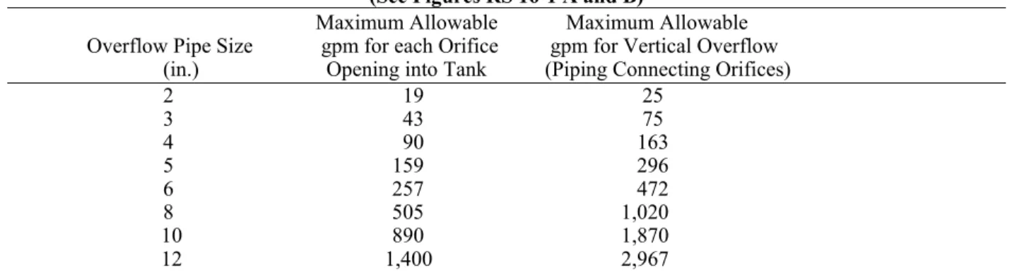
RS 16-7 Minimum Rate of Flow and Minimum Required Pressure During Flow for Sizing Individual Branch Supplies for Plumbing Fixtures RS 16-8 Size of Overflows for Gravity and Suction
Tanks
RS 16-9 Size of Weirs for Gravity and Suction Tanks RS 16-10 Suction Tank Sizes
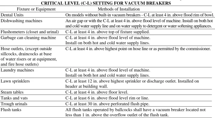
RS 16-11 Cross-Connection Where Protective Devices are Required and Critical Level (C-L) Setting for Vacuum Breakers
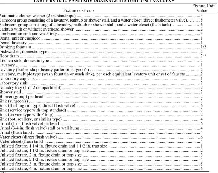
RS 16-12 Sanitary Drainage Fixture Unit Valves RS 16-13 Maximum Permissible Loads for Sanitary
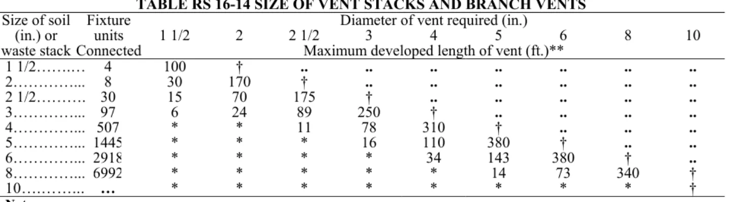
Drainage Piping (in terms of fixture units) RS 16-14 Size of Vent Stacks and Branch Vents RS 16-15 Deleted
RS 16-16 Deleted
RS 16-17 Size of Horizontal Storm Drains RS 16-18 Size of Vertical Leaders RS 16-19 Size of Roof Gutters* *Local Law 85-1973
RS 16-20 Fixture Unit-Drainage Square Footage Equivalent
RS 16-21 Minimum Distances Between Sewage System Components and Between Components and Encumbrances
RS 16-22 Minimum Capacity of Septic Tanks RS 16-23A Design Data for Absorptive Capacity of
Disposal Field and Seepage Pits RS 16-23BDesign Data for Absorptive Capacity of
Disposal Field and Seepage Pits RS 16-24 Limiting Dimensions of Disposal Field
Components
RS 16-25 Minimum Number of Fixtures for Hospitals and Institutions
RS 16-26 Stack Sizes for Bedpan Steamers and Boiling Type Sterilizers, and of Connections Permitted
RS 16-27 Stack Sizes for Pressure Sterilizers and Number of Connections Permitted RS 16-28 Fixture Water Supply Protection
LIST OF ILLUSTRATIONS Figure No.
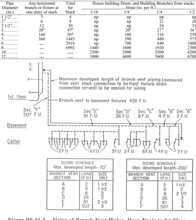
RS 16-1 Methods of Connecting Overflow from Gravity House and Suction Water Supply Tanks RS 16-2 Sizing of Branch Vent Piping and Drop Vents
to First Floor, Basement and Cellar Fixtures RS 16-3 Deleted
RS 16-4 Vent Arrangements RS 16-5 Deleted
RS 16-6 Offsets in Buildings Five Stories or More RS 16-7 Relief Vents for Stack of More than Ten Branch
Intervals
RS 16-8 Suds Pressure Zones
RS 16-9 Combination Waste and Vent Oil Waste Drainage
**RS 16-9A Yard Drain With Sump
**RS 16-9B Detail of Dry Well With Sand Column RS 16-10 Acid Drainage for Buildings Four Stories or Less
RS 16-11 Acid Drainage for Buildings Over Four Stories
*RS 16-12A Typical Concrete Septic Tank *RS 16-12B Typical Metal Septic Tank *RS 16-13A Absorption Type System *RS 16-13B Absorption Type
*Local Law 85-1973 **Local Law 103-1989
Section P100.0 Definitions
The following definitions shall be used in the application of this reference standard.
AIR-BREAK (DRAINAGE SYSTEM).—A piping arrangement in which a drain from a fixture, appliance, or device discharges through an air break into a fixture, receptacle, or interceptor at a point above the flood level rim of the receptacle.
AIR GAP (WATER DISTRIBUTION SYSTEM).— The unobstructed vertical distance through the free atmosphere between the lowest opening from any pipe or faucet supplying water to a tank, plumbing fixture, or other device and the flood level rim of the receptacle.
BACKFLOW.—The flow of water or other liquids, mixtures, or substances into the distributing pipes of a potable supply of water from any source or sources other than its intended source. (See back-siphonage.)
BACK-SIPHONAGE.—The flowing back of used, contaminated, or polluted water from a plumbing fixture or vessel into a water-supply system due to a negative pressure in such pipe. (See backflow.)
BATTERY OF FIXTURES.—Any group of two or more similar adjacent fixtures that discharge into a common horizontal waste or soil branch.
BRANCH.—That part of a piping system other than a main, riser, or stack that extends to fixtures on two or less consecutive floors.
BRANCH INTERVAL.—A distance along a soil or waste stack corresponding in general to a story height, but in no case less than 8 ft. within which the horizontal branches from one floor or story of a building are connected to the stack.
BRANCH VENT.—A vent connecting one or more individual vents with a vent stack or stack vent.
BUILDING HOUSE DRAIN.—That part of the lowest piping of a drainage system that receives the discharge from the soil, waste, and other drainage pipes of the building and conveys it to the building house sewer by gravity; the building house drain shall be considered to extend 5 ft. outside the building wall.
BUILDING HOUSE DRAIN (COMBINED).— A building house drain that conveys both storm water and sewage or other drainage.
BUILDING HOUSE DRAIN (SANITARY).— A building house drain carrying sewage only.
BUILDING GRAVITY DRAINAGE SYSTEM.— A drainage system that drains by gravity into the
215 building house sewer.
BUILDING HOUSE SEWER.—That part of the horizontal piping of a drainage system that extends from the end of the building house drain and that receives the discharge of the building house drain and conveys it to a public sewer, private sewer, individual sewage-disposal system or other point of disposal.
BUILDING HOUSE SEWER (COMBINED).— A building house sewer that conveys both sewage and storm water and other clear water wastes.
BUILDING HOUSE SEWER (SANITARY).— A building house sewer carrying sewage only.
BUILDING HOUSE STORM DRAIN.—That part of the lowest piping of a storm drainage system that receives clear water drainage from leaders, surface run-off, ground water, subsurface water, condensate, cooling water or other similar storm or clear water drainage pipes inside of the walls of the building and conveys to it to the building house storm sewer by gravity; the building house storm drain shall be considered to extend 5 ft. outside of the building wall.
BUILDING HOUSE STORM SEWER.— That part of the horizontal piping of the storm drainage system that extends from the building house storm drain to the public storm sewer, combined sewer, or other point of disposal.
BUILDING SUB-HOUSE DRAIN.—The portion of a house drainage system that conveys the drainage from the lower portion of the building to an ejector pit or sump pit from which it is pumped into the building house sewer.
BUILDING HOUSE TRAP.—A trap, or assembly of fittings, installed in the building house drain to prevent circulation of air between the house drainage system and the building house sewer.
CESSPOOL.—A covered excavation in the ground that receives the discharge of domestic sewage or other organic wastes from a drainage system, so designed as to retain the organic matter and solids, but permitting the liquid to seep through the bottom and sides.
COMBINATION FIXTURE.—A fixture combining one sink and tray or two- or three-compartment sink or tray in one unit.
COMBINATION WASTE AND VENT SYSTEM.—A specially designed system of waste piping embodying the horizontal wet venting of one or more sinks or floor drains by means of a common waste and vent pipe.
COMMON VENT.—A vent connecting at the junction of two fixture drains and serving as a vent for both fixtures and drains.
CONTINUOUS VENT.—A vertical vent that is a continuation of the drain to which it connects.
CONTINUOUS WASTE.—A drain from two or three fixtures connected to a single trap.
CROSS-CONNECTION.—A physical connection
or arrangement between two otherwise separate piping systems, one of which contains potable water and the other with either water of unknown or questionable safety or steam, gases, or chemicals whereby there can be a flow from one system to another.
DEAD END.—A branch leading from a soil, waste, or vent pipe, building house drain, or building house sewer, which is terminated to a developed distance of 2 ft. or more by means of a plug or other closed fitting.
DEVELOPED LENGTH.—The length along the center line of pipe and fittings, both horizontal and vertical.
DIAMETER.—Unless otherwise specifically stated, the term "diameter" is the nominal diameter as designated commercially.
DOMESTIC SEWAGE.—The water-borne wastes derived from ordinary living processes.
DRAIN.—Any pipe that carries waste water or water-borne wastes in a building drainage system.
DRAINAGE SYSTEM.—Includes all the piping within public or private premises, which conveys sewage, rain water, or other liquid wastes to a legal point of disposal, but does not include the mains of a public sewer system or private or public sewage-treatment or disposal plant.
DRY WELL.—See leaching well or pit. DUAL VENT.—See common vent.
EFFECTIVE OPENING.—The minimum cross-sectional area at the point of water-discharge, measured or expressed in terms: (1) diameter of a circle; (2) if the opening is not circular, the diameter or a circle of equivalent cross-sectional area.
EXISTING WORK.—A plumbing system or any part thereof installed prior to the effective date of this code.
FIRE LINE.—A system of pipes and equipment used exclusively to supply water for extinguishing fires.
FIXTURE.—See plumbing fixture.
FIXTURE BRANCH.—A water supply pipe connecting one or more fixtures to a main water supply header or riser.
FIXTURE DRAIN.—The drain from the trap of a fixture to the junction of that drain with any other drain pipe.
FIXTURE SUPPLY.—A water-supply pipe connecting the fixture with the fixture branch.
FLOOD LEVEL RIM.—The top edge or rim of a receptacle from which water can overflow regardless of the location of any overflow piping from the receptacle.
FLOODED.—A fixture is flooded when the liquid therein rises to the flood level rim.
FLUSH VALVE.—A device located at the bottom of the tank for the purpose of flushing water closets and similar fixtures.
FLUSHOMETER VALVE.—A device that discharges a predetermined quantity of water to fixtures
for flushing purposes and is actuated by direct water pressure. FROSTPROOF WATER CLOSET.—A hopper that has no water in the bowl and has the trap and the control valve for its water supply installed below the frost line.
GAS DISTRIBUTION PIPING.—All piping from the house wide of the gas meter piping that distributes the gas supplied by a public utility to all fixtures and apparatus used for illumination or fuel in any building
GAS METER PIPING.—The piping from the shut-off valve inside the building to the outlet of the meter. GAS SERVICE PIPING.—The supply pipe from the street main through the building wall and including the stopcock or shut-off valve inside the building.
INDIRECT WASTE PIPE.—A drain pipe used to convey liquid wastes that does not connect directly with the drainage system, but which discharges into the house drainage system through an air break into a trap, fixture, receptacle, or interceptor.
INDUSTRIAL WASTE.—A liquid, gaseous or solid substance, or a combination thereof resulting from any process of industry, manufacturing, trade or business or from the development or recovery of any natural resource.
INTERCEPTOR.—A device designed and installed so as to separate and retain deleterious, hazardous, or undesirable matter from normal wastes and permit normal sewage or liquid wastes to discharge into the disposal terminal by gravity.
LEACHING WELL OR PIT.—A covered pit constructed so as to permit the liquid contents to seep into the ground.
LEADER.—A vertical drainage pipe for conveying storm water from roof or gutter drains to the building storm drain, building house drain (combined). or other means of disposal. The leader shall include the horizontal pipe to a single roof drain or gutter drain.
LIQUID WASTE.—The discharge from any fixture, appliance, or appurtenance, in connection with a plumbing system that does not receive fecal matter.
LOAD FACTOR.—The percentage of the total connected fixture unit flow rate that is likely to occur at any point in the drainage system.
LOCAL VENTILATING PIPE.—A pipe on the fixture side of the trap through which vapor or foul air is removed from a room or fixture.
NORMAL SEWAGE.—Normal sewage means "normal sewage" as defined in the rules and regulations of the Department of Public Works.
PITCH.—See grade.
pH VALUE.—An arbitrary symbol adopted to express the degree of acidity or alkalinity of a solution. It is the logarithm of the reciprocal of the hydrogenion concentration, in gram mols per liter at 71.6oF. A pH of 7.0 represents a neutral solution, lower values represent acidity, higher values alkalinity.
PIPING.—As used in this reference standard, piping shall include fittings, valves, and other accessories or appurtenances required to make a complete installation.
PLUMBING.—The practice, materials, and fixtures used in the installation, maintenance, extension, repair, replacement, relocation and alteration of all piping, fixtures, appliances, and appurtenances in connection with any of the following, sanitary drainage or storm drainage facilities, the venting system, and public or private water supply systems, within or adjacent to any building; also, the practice and materials used in the installation, maintenance, extension, repair, replacement, relocation or alteration of storm water, liquid-waste, or sewerage, and water-supply systems of any premises in their connection with any point of public disposal or other acceptable terminal.
PLUMBING FIXTURES.—Installed receptacles, devices, or appliances that are supplied with water or that receive or discharge liquids or liquid-borne wastes.
PLUMBING SYSTEM.—Includes the water-supply and distribution pipes; plumbing fixtures and traps; soil, waste, and vent pipe; building house drains and building house sewers including their respective connections, devices, and appurtenances within the property lines of the premises, and water-treating or water-using equipment.
POOL.—A water receptacle used for swimming or as a plunge or other bath, designed to accommodate more than one bather at a time. Also a receptacle used for decorative purposes.
POTABLE WATER.—Water free from impurities present in amounts sufficient to cause disease or harmful physiological effects. Its bacteriological and chemical quality shall conform to the requirements of the department of health of the City of New York.
PRIVATE OR PRIVATE USE.—In the classification of plumbing fixtures, "private" applies to fixtures in residences and apartments and to fixtures in bathrooms of hotels and similar installations where the fixtures are intended for the use of a family or an individual.
PRIVATE SEWER.—A sewer privately owned and controlled by public authority only to the extent provided by law.
PUBLIC OR PUBLIC USE.—In the classification of plumbing fixtures, "public" applies to fixtures in general toilet rooms of schools, gymnasiums, hotels, railroad stations, public buildings, bars, comfort stations, and other installations (whether pay or free) where fixtures are installed so that their use is similarly unrestricted.
PUBLIC SEWER.—A common sewer directly controlled by public authority.
RELIEF VENT.—A vent installed so as to permit additional circulation of air between the drainage and vent systems where the drainage system might otherwise be air bound.
217 RISER.—A water-supply pipe that extends
vertically one full story or more to convey water to branches or fixtures.
ROOF DRAIN.—A drain installed to receive water collecting on the surface of a roof and to discharge it into the leader (downspout).
ROUGHING-IN.—The installation of all parts of the plumbing system that can be completed prior to the installation of fixtures. This includes drainage, water-supply, and vent piping, and the necessary fixture supports.
SANITARY SEWAGE.—See domestic sewage. SANITARY SEWER.—A pipe that carries sewage and excludes storm, surface and ground water.
SEEPAGE PITS OR WELLS.—A covered pit with open jointed or perforated lining into which the septic tank effluent is discharged. The liquid portion of the sewage seeps into the surrounding porous soil. The remaining solids or sludge is retained in the pit.
SEPARATOR.—See interceptor.
SEPTIC TANK.—A watertight receptacle that receives the discharge of a drainage system or part thereof, and is designed and constructed so as to separate solids from the liquid, digest organic matter during a period of detention, and allow the liquids to discharge into the soil outside of the tank through a system of open-joint or perforated piping, or seepage pit.
SEWAGE.—Any liquid waste containing animal or vegetable matter in suspension or solution, and may include liquids containing chemicals in solution.
SEWAGE DISPOSAL SYSTEM.—A system for the disposal of domestic sewage by means of a septic tank, cesspool, or mechanical treatment, all designed for use apart from a public sewer to serve a single establishment, building, or development.
SEWAGE EJECTOR.—A mechanical device used to pump or eject sewage.
SEWAGE EJECTOR PIT.—A tank or pit that receives sewage located below the normal grade of the gravity system and that must be emptied by mechanical means.
SIDE VENT.—A vent connecting to the drain pipe through a fitting at an angle not greater than 45 degrees to the vertical.
SLOPE.—See grade.
SOIL PIPE.—A pipe that conveys sewage containing fecal matter.
SPECIAL WASTE.—Waste which requires special treatment before entry into the normal plumbing system.
STACK.—A general term for any vertical line of soil, waste, vent, or inside leader piping. This does not include vertical fixture and vent branches that do not extend through the roof or that pass through not more than two stories before being reconnected to the vent stack or stack vent.
STACK VENT (SOMETIMES CALLED A
WASTE VENT OR SOIL VENT).—The extension of a soil or waste stack above the highest horizontal drain connected to the stack.
STACK VENTING.—A method of venting a fixture or fixtures through the soil waste stack.
STORM DRAIN.—See building storm drain. STORM SEWER.—A sewer used for conveying rain water, surface water, condensate, cooling water, or similar clear liquid wastes.
SUB-HOUSE DRAIN.—See building sub-house drain.
SUB-SURFACE DISPOSAL FIELD.—A system of open jointed tile or perforated pipes or drains through which storm water or the sewage effluent from a septic tank is distributed beneath the surface of the ground for absorption into the soil, as well as evaporation into the air during favorable weather conditions.
SUB-SOIL DRAIN.—A drain that receives only sub-surface or seepage water and conveys it to a place of disposal.
SUMP PIT.—A tank or pit that receives clear liquid wastes, that do not contain organic materials or compounds subject to decomposition, located below the normal grade of the gravity system and which must be emptied by mechanical means.
SUMP PUMP.—A mechanical device used to eject or pump the liquid waste from a sump pit into the gravity drainage system.
SUPPORTS.—Devices for supporting and securing pipe, fixtures, and equipment.
SWIMMING POOL.—Any structure, basin, chamber or tank containing water for swimming, diving, or recreational bathing and having a depth of 2 ft. or more at any one point.
TRAP.-A fitting or device with a smooth interior passage, the inside diameter of which is equal to the inlet pipe diameter, and which provides a liquid seal of at least 2 in.
TRAP SEAL.-The maximum vertical depth of liquid that a trap will retain, measured between the crown weir and the top of the dip of the trap. Seal 2 in. in normal traps and 3 in. or more for deep seal traps.
VACUUM BREAKER.—A device used to prevent backflow by siphonic action.
VENT PIPE.—See vent system.
VENT STACK.—A vertical vent pipe installed primarily for the purpose of providing circulation of air to and from any part of the drainage system.
VENT SYSTEM.—A pipe or pipes installed to provide a flow or air to or from a drainage system or to provide a circulation of air within such system to protect trap seals from siphonage and back pressure.
VERTICAL PIPE.—Any pipe or fitting that is installed in a vertical position or that makes an angle of not more than 45 degrees with the vertical.
liquid waste, free of fecal matter.
WATER-DISTRIBUTION PIPING.—In a building or premises, piping that conveys water from the water service pipe to the plumbing fixtures and other water outlets.
WATER (STREET) MAIN.—A water-supply pipe for public or community use controlled by public authority.
WATER OUTLET.—As used in connection with the water-distributing system, is the discharge opening for the water to a fixture; to atmospheric pressure (except into an open tank which is part of the water-supply system); to a boiler or heating system; to any water-operated device or equipment requiring water to operate, but not a part of the plumbing system.
WATER SERVICE PIPING.—That portion of the water supply system extending from the public street water main to the house control valve inside the building to a point where the supply is fully metered.
WATER SUPPLY SYSTEM.—Consists of the water-service pipe, the water-distribution pipes, and the necessary connecting pipes, fittings, control valves, and all appurtenances used for conveying water.
YOKE VENT.—A pipe connecting upward from a soil or waste stack to a vent stack for the purpose of preventing pressure changes in the stack. Section P101.0 General Provisions
P101.1 Protection of
Pipes.-(a) Breakage.—Pipe passing under or through walls shall be protected from breakage. Any plumbing pipe passing under a footing or through a foundation wall shall be protected from carrying any weight of the structure by an arch or lintel constructed above the pipe by an iron-pipe sleeve built into the masonry wall and greater in size than the pipe passing through the wall, or by an equivalent method of protection.
(b) Corrosion.—Pipe subject to external corrosion by passing through or under corrosive material shall be protected against external corrosion by protective coating, wrapping, or other equivalent means that will resist such corrosion.
P101.2 Trenching, Excavation, and Backfill.-(a) Material for backfill.—Trenches shall be backfilled by hand and tamped, in 6 in. layers, for 1 ft. above the crown of the pipe. Loose earth, free from frozen earth chunks or other material that may break the pipe, shall be used to provide firm bedding around the pipe.
(b) Trenching
methods.-(1) Trenches shall be excavated to a width sufficient to permit workmen to properly install the pipe. The bottom of the pipe trench shall be constructed so that the pipe between joints will have solid bearing along its entire length. Bell holes shall be provided at points where the
pipe is joined together to insure uniform bearing along the length of the pipe. In rock excavation the material shall be removed 3 in. to 6 in. below the grade line of the trench and then backfilled and tamped to grade with sand to provide a uniform firm foundation for the pipe. If soil materials of class 11-65 or poorer are encountered the pipe shall be supported in accordance with the applicable provisions of the building code for structural work. (2) Where open trenches are impractical, pipe may be installed by driving or tunneling methods acceptable to the commissioner. Where driving or tunneling methods are employed, special care shall be exercised to protect the pipe from breakage and against earth settling or caving. Pipe may be installed in a previously driven conduit slightly larger than the pipe. Earth tunnels with a length not exceeding the depth of the trench may be employed, providing adequate supporting structures are provided to prevent future settling or caving.
(3) Permits for sidewalk and street openings shall be obtained from the department of highways.
P101.3
Sleeves.-(a) The annular space between sleeves and pipe through foundation or exterior building walls shall be filled or partly caulked with polysulphide compound, lead, or other equivalent waterproofing material. (b) Where pipes and sleeves pass through construction required to have a fire-resistance rating, they shall comply with the applicable requirements of the building code.
P101.4 Ratproofing.—In an apartment or in dwelling units, and in buildings or building areas used for the storage or preparation of food, the openings in walls, floors, or ceilings for the passage of pipes shall be closed and protected by metal collars securely fastened to the structure.
P101.5 Toilet Facilities for Workmen.—The site upon which any building, except a one- or two-family dwelling, is being constructed shall be provided with toilet facilities for use of workmen as specified in Table RS 16-5.
Section P102.0 Materials
P102.1 General
Requirements.-(a) Materials required.—All materials used in the construction of any plumbing system, fixtures, or equipment shall be as required by this reference standard. (b) Installation.—All materials installed in plumbing systems shall be handled and installed so as to avoid damage to the material.
P102.2 Standards for Plumbing Materials.-(a) Materials.—Materials shall conform to one of the standards cited in Table RS 16-1. Equivalent materials not listed in Table RS 16-1 may be used provided they are approved.
*TABLE RS 16-1 STANDARDS FOR PLUMBING MATERIALSa
Materials ANSI Other
Ferrous Pipe and Fittings-
Cast iron soil pipe and fittings coupling... None CISPI 310-1985 Hubless cast iron soil pipe ... None CISPI 301-1985 Cast iron soil pipe and fittings,
extra heavy and service weights ...… None CS188-66 Cast iron water pipe ...… A21.6-1962
A21.8-1962
Cast iron pipe, drainage, vent and waste… None FS-WW-P356-1936
Cast iron pipe, pressure (50 lb.)
gas and water ……… None FS-WW-P360a-1959
Cast iron (threaded) pipe ... A40.5-1943 Cast iron (threaded) fittings ... B16.4-1963 Cast iron drainage fittings ... B16.12-1965
Galvanized pipe and fitting ... None FS-WW-P406(1) 1945 Malleable iron fittings (threaded)
150 lbs. ... B16.3-1963 300 lbs. ... B16.3-1963 Steel pipe, seamless and welded,
black and zinc coated
(not intended for close coiling) ….... B36.20-1966 Steel pipe, seamless and welded,
black and zinc coated
(suitable for close coiling) ……... B36.1-1966 Stainless steel pipe ... B36.19-1965
Union, malleable iron or steel ... None *FS-WW-O531a-1957
FS-WW-U536(1)-1953 Wrought-iron pipe ... B36.2-1966
Valves, cast iron, gate 125 and
250 lb. threaded and flanged ... None FS-WW-V58(1)-1946 Pipe fittings, bronze and ferrous
(bushings, plugs and locknuts),
threaded ..………... None FS-WW-P471(1)-1946
Nipples, pipe threaded ... None FS-WW-N351a-1956 Non-Ferrous Pipe and Fittings-
Finished and rough brass
plumbing fixture fittings ... None ASME A112.18.1M-79 Brass tube ... H36.1-1967
Brass pipe ... H27.1-1963 Brass or bronze flanges and
flanged fittings, 150 and 300 lb. ... B16.24-1962 Brass or bronze screwed fittings,
125 lb and 250 lb. .………... B16.15-1964 Cast-bronze solder joint pressure
fittings ………... B16.18-1963
Cast-brass solder joint drainage
fittings .………... B16.23-1960
Copper pipe ... H26.1-1963 Copper pipe, threadless ... H26.2-1963 Seamless copper tube ... H23.3-1965 Copper water tube, type K, L ... H23.1-1967 Wrought copper and wrought
bronze solder joint fittings ...…... H16.22-1963
*As enacted but “FS-WW-U531a-1957” probably intended.
Wrought copper and wrought copper
alloy solder joint drainage fittings….. H16.29-1966
Lead pipe and traps ... None WW-P325-1944 Unions, brass or bronze, 250 lb. ... None FS-WW-U516-1933 Valves, bronze; angle, check and
globe, 125 and 150 lb., threaded
and flanged ………... None FS-WW-V51a(2)-1954
Valves; bronze, gate, 125 and
150 lb., threaded and flanged ... None FS-WW-V54b-1962 Pipe fittings, bronze and ferrous
(bushings, plugs and locknuts),
threaded ………... None FS-WW-P471(1)-1946
Non-Metallic Pipe and Fittings-
Asbestos cement (sewer) pipeb... None ASTM-C428-65T
Asbestos cement underdrain ... None ASTM-C508-67T Clay drain tile ... None ASTM-C4-62 Concrete sewer pipe, reinforced ... None ASTM-C76-65T Concrete sewer pipe, nonreinforced…. None ASTM-C14-67
Clay sewer pipe, standard strength ... A106.3-1965 ASTM-C13-64T Vitrified clay sewer pipe, salt-glazed
and unglazed extra strength………... None ASTM-C200-65T Vitrified clay sewer pipe, ceramic
glazed, extra strength …………... None FS-SSP361b-1962 Vitrified clay sewer pipe, perforated,
standard strength ………... A106.1-1962 Plumbing Fixtures-
Drinking fountains ... Z4.2-1942
Enameled cast iron plumbing fixtures.. None ASME 112.19.1M-87 Earthenware (vitreous glazed)
plumbing fixtures ..…………... None CS111-43
Formed steel enameled sanitary ware.. None FS-WW-P541b(2)-1962 Formed metal porcelain enameled
sanitary ware ...…………... None FS-WW-P541b(2)-1962 Heaters, water, instantaneous
(steam-water converter type) ... None FS-WW-H191-1954 Plumbing fixtures (for) land use ... None FS-WW-P541b(2)-1962 Stainless steel plumbing fixtures ... None ASME A112.19.3M-87
Vitreous china plumbing fixtures ... A112.19.2M-82 Stills, water; portable (without heating
device) for U.S.P." distilled water"…. None FS-RR-S726(1)-1950
Porcelain enameled formed steel plumbing fixtures. None ASME A112.19.4M-84 Miscellaneous Materials and
Standards-
Automatic relief valves ... Z21.22-1964 Air gap standards ... A40.4-1942 Backflow preventers ... A40.6-1943
Brass cleanout plugs ... None *FS-WW-P401(3)-1951 Brazing filler metal ... None ASTM-B260-62T
Caulking lead, Type I ... None FS-QQ-L156(1)-1946 Caulking: lead wool and lead pig ... None FS-QQ-C40-1963
Cement lining ... A21.4-1964
Coal-tar, enamel, protective coating.... None AWWA-C203-62
221 Fixture setting compound ... None FS-HH-C536a-1954
Flange dimensions, standard classes 125 and 250 cast iron flanges, classes 150, 250 and
300 bronze flanges (land use) ... None FS-WW-F406a(1)-1943 Galvanized iron and steel sheets ... G8.2-1964
Gaskets, plumbing-fixture-setting ... None FS-HH-G116-1936 Hangers and supports, pipe ... None FS-WW-H171b-1959 Resilient joints ... None ASTM-C425-64 Rubber gaskets (concrete sewer pipes). None ASTM-C443-65 Seal joints, sewer ... None FS-SS-S169-1954 Sheet brass, leaded and non-leaded ... None ASTM-B36-66
ASTM-B121-66 Sheet copper ... None ASTM-B152-60 Sheet lead, grade A ... None FS-QQ-L201d-1961 Solder metal ... None ASTM-B32-66T Steel septic tanks ... None CS177-62 Domestic hot water heaters ... Z21.10.1-1966 C72.1-1949
Notes-** a Abbreviations used in the table refer to the following organizations:
***USASI-United States of America Standards Institute ASTM—American Society for Testing and Materials AWWA—American Water Works Association CS—Commercial Standards
FS—Federal Specifications
*Local Law 100-1989; Local Law 29-1989; Local Law 63-1976
**List as enacted, but probably intended to add "ASME-American Society of Mechanical Engineers." ***As enacted, but probably intended to read "ANSI-American National Standards Institute, Inc."
b Asbestos cement building sewer pipe shall meet the requirements of ASTM Standard C428-63T expanded as follows: (1) Additional sizes 4 in. and 5 in.
(2) No hydrostatic test for building sewer service (3) Flexural strength:
Size (in.) Length (in.) Class 1500 Class 2400 Class 3300
4 10 550 775 1100 4 13 750 1000 1350 5 10 950 1375 1900 5 13 1250 1775 2350 6 10 1500 1700 2100 6 13 2000 2200 2600
(4) Crushing strength: Include 4 in. and 5 in. for Classes 1500, 2400, 3300 Crushing test: One specimen from each 300 lengths of 4 in., 5 in., and 6 in. size pipes.
†(b) Plastic piping and fittings.-Plastic piping and fittings may be used only in residential buildings of three stories or less in height, except that corrugated polyethylene piping with a diameter of twelve inches or more and plastic fittings may be used in connection with any type of building for underground yard drainage and storm water piping when used outside of the foundation walls of the building and not connecting to any piping system from the interior of the building and shall be approved. Plastic drain, waste and vent pipe and fittings used inside of residential buildings of three stories or less in height shall be required to conform with ASTM Standard D2661-97 Specification for Acrylonitrile-Butadiene-Styrene (ABS) Schedule 40 Plastic Drain, Waste, and Vent Pipe and Fittings or ASTM Standard D2665-98 Specification for Poly Vinyl Chloride (PVC) Plastic Drain, Waste, and Vent Pipe and Fittings, as well as the International Association of Plumbing and Mechanical Officials Installation Standards for ABS Building Drain, Waste and Vent Pipe and Fittings (IAPMO IS 5-92) and PVC Building Drain, Waste and Vent Pipe and Fittings (IAPMO IS 9-95) and Non-Metallic Building Sewers (IAPMO IS 1-91).
†Local Law 2-2001; Local Law 58-1973; Local Law 75-1971 P102.3 Identification of Materials.-Materials shall be identified as provided herein.
P102.4 Piping System Materials.-(a) Water supply
systems.-*(1) WATER SERVICE PIPE.-Water service piping within the property line shall be of red brass or copper pipe; type K copper tube; type "TP" threadless copper; cast iron or ductile iron water pipe; or plastic pipe in accordance with section P102.2(b). Water service piping outside of the property line shall comply with requirements of the department of environmental protection. When used underground in corrosive soil or fill, all ferrous pipe and fittings shall be coal tar, enamel coated. Threaded joints shall be coated and wrapped after installation regardless of the nature of the soil. (2) WATER DISTRIBUTION SYSTEM PIPE.-Water distribution system piping shall be of red brass pipe, type "TP" threadless copper pipe, hard temper type "K" copper tube, hard temper type "L" copper tube, galvanized wrought iron pipe, galvanized steel pipe, or ductile cast iron properly anchored. Cast iron and ductile-iron pipe may be cement lined in accordance with ANSI A21.4-1971. Type "L" copper tube shall not be installed in soil or concrete floor fill.
***(b) Drainage
systems.-*Local Law 29-1987; Local Law 63-1976; Local Law 58-1973 ***Local Law 63-1976
(1) ABOVE GROUND PIPING WITHIN BUILDINGS.-Soil, waste, and storm water or leader piping above ground in buildings shall be brass pipe, copper pipe,
hard temper type "K" copper tube, hard temper type "L" copper tube, extra heavy cast iron soil pipe, service weight cast iron soil pipe, no-hub cast iron soil pipe, AWWA class 22 or stronger iron, stainless steel pipe, threaded cast iron pipe, galvanized wrought iron pipe, galvanized steel pipe, or lead pipe, singly or in combination. Cast iron piping and fittings may be coated or uncoated. The maximum developed length to which lead may be used in connection with any one fixture shall be 5 feet. Plastic pipe will be permitted if it conforms to the requirements set forth in section P102.2(b). (2) UNDERGROUND PIPING WITHIN All underground building drains shall be extra heavy cast iron soil pipe, service weight cast iron soil pipe, no-hub cast iron soil pipe, AWWA Class 22 or stronger cast iron water piping, ductile cast iron, brass pipe, type "K" hard temper copper tube, or plastic pipe conforming to the requirements set forth in section P102.2(b). Cast iron pipe and fittings may be coated or uncoated. (3) BUILDING HOUSE
SEWERS.-**a. Building house sewers shall be extra heavy iron soil pipe and fittings, service weight cast iron soil pipe and fittings, no-hub cast iron soil pipe and fittings, AWWA class 22 or stronger cast iron water piping, ductile cast iron and fittings, or plastic pipe conforming to the requirements set forth in section P102.2(b), a minimum of 8 in. size in the borough of Manhattan and 6 in. in the other boroughs, except that a house sewer from one- and two-family dwellings may be the size specified in Table RS 16-13 and may run up to the street line. Cast iron pipe and fittings may be coated or uncoated.
**Local Law 58-1973; Local Law 39-1972
b. Building house sewers for one- and two-family dwellings when installed in a separate trench from the water service may be of vitreous pipe or asbestos cement pipe. c. Existing building sewers may be used in connection with a new building sewer and drainage system only when found by examination and test to conform to the new system in quality of material.
†(4) UNDERGROUND YARD DRAINAGE AND STORM WATER PIPING.-Underground yard drainage and storm water piping within the property line but outside of the foundation walls of the building shall be extra heavy cast iron soil pipe, AWWA Class 22 or stronger cast iron water pipe, ductile cast iron, service weight cast iron, no-hub cast iron soil pipe, asbestos cement pipe, vitreous tile pipe, concrete pipe, or plastic pipe conforming to the requirements set forth in section P102.2(b). Cast iron pipe and fittings may be coated or uncoated.
†Local Law 63-1976; Local Law 58-1973
(5) CHEMICAL WASTES (ACID
WASTES)-Separate drainage systems for chemical waste shall be of acid resistant material when the waste water at any point in the system will have a pH value of less than 4.5
223 or more than 9.5. Chemical waste drainage piping shall
be low expansion, borosilicate glass pipe; high silicon cast iron pipe; chemical stoneware pipe; chemical lead pipe; or approved plastic pipe regardless of building height, or other equivalent materials. Materials may be used singly or in combination.
***(c) Venting
Systems.-(1) ABOVE GROUND VENTING.-Vent piping installed above ground shall be brass pipe, type "TP" threadless copper pipe, hard temper type "K" copper tube, hard temper type "L" copper tube; extra heavy cast iron soil pipe, service weight cast iron soil pipe, no-hub cast iron soil pipe, AWWA Class 22 or stronger cast iron water pipe, ductile cast iron, threaded cast iron pipe, galvanized wrought iron pipe, galvanized steel pipe, singly or in combination. Cast iron pipe and fittings may be coated or uncoated. Plastic pipe will be permitted if it conforms to the requirements set forth in section P102.2(b).
***Local Law 63-1976
(2) UNDERGROUND VENTING. Underground vent piping shall be extra heavy cast iron soil pipe, service weight cast iron soil pipe, no-hub cast iron soil pipe, AWWA Class 22 or stronger cast iron water pipe, ductile cast iron, brass pipe, copper pipe, or type "K" hard temper copper tube. Cast iron pipe and fittings may be coated or uncoated.
(3) CHEMICAL WASTE SYSTEMS.-Vent piping for chemical waste systems shall conform to the requirements for the chemical waste pipe.
(d) Fittings.-The materials of which water supply, drainage, and venting system pipe fittings are made shall conform to the type of piping material used in the water supply, drainage, or venting system (i.e., brass or bronze fittings with copper pipe or tubing), except that black cast iron may be used with brass or galvanized pipe. Threaded drainage pipe fittings shall be of the recessed drainage type. Fittings used to prevent or
reduce galvanic corrosion may be installed within a system only at the point of isolation.
(e) Other piping systems and miscellaneous materials.-(1) ROOF DRAINS.-Roof drains shall be cast iron, bronze, copper, brass, stainless steel, lead, or other equivalent corrosion resistant material.
(2) EXTERIOR LEADERS (DOWNSPOUTS).-Exterior leaders and gutters installed above ground level shall be sheet metal or copper, aluminum, galvanized steel, stainless steel, or other equivalent corrosion resistant material. Pipe (galvanized steel, galvanized wrought iron, cast iron or brass) may be used for the first 15 ft. of leader extending up from grade, providing that the pipe is securely anchored with offset clamps to the face of building at two points in the vertical section of pipe. Pipe will not be acceptable above 15 ft.
*(3) SUBSOIL DRAINS.-Subsoil drains shall be clay tile that is open jointed, horizontally split, or perforated; open jointed cast iron soil pipe; porous concrete pipe; asbestos cement pipe that is open jointed, horizontally split, or perforated or plastic pipe in accordance with section P102.2(b) that is open jointed, horizontally split, or perforated.
*Local Law 39-1972; Local Law 58-1973
(4) LEAD BENDS AND TRAPS.-The walls of lead bends and traps shall be at least 1/8 in. thick.
(5) SHEET COPPER.-Sheet copper shall weigh at least 12 ounces per sq. ft.
(6) SHEET LEAD.-Sheet lead shall weight at least 4 psf. (7) CAULKING FERRULES.-Caulking ferrules shall be brass or copper, and shall be made in accordance with Table RS 16-3.
Ferrules may be tapped "T" or tapped "Y" types with bossings provided on the tapped connection.
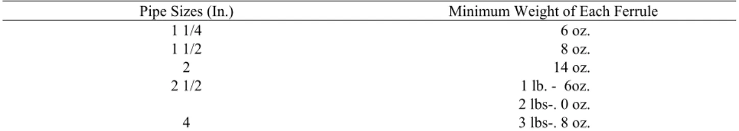
(8) SOLDERING BUSHINGS.-Soldering bushings shall be brass or copper in accordance with Table RS 16-4.
TABLE RS 16-3 CAULKING FERRULES
Pipe Sizes (In.) Inside Diameter of Ferrule (In.) Minimum Length of Ferrule (In.) Minimum Weight of Each Ferrule
2 2 1/4 4 1/2 1 lb. - 0 oz.
3 3 1/4 4 1/2 1 lb. - 12 oz.
4 4 1/4 4 1/2 2 lbs. - 8 oz.
TABLE RS 16-4 SOLDERING BUSHINGS
Pipe Sizes (In.) Minimum Weight of Each Ferrule
1 1/4 6 oz. 1 1/2 8 oz. 2 14 oz. 2 1/2 1 lb. - 6oz. 2 lbs-. 0 oz. 4 3 lbs-. 8 oz.
(9) FLOOR FLANGES.-Floor flanges for water closets or similar fixtures shall be of cast brass at least 1/8 in. thick, of cast iron at least 1/4 in. thick and having a caulking depth not less than 2 in., or of hard lead weighing at least 1 lb.-9 oz. and composed of lead alloy having at least 7.75 per cent antimony by weight. The use of floor flanges of other equivalent materials may be used. (10) CLEANOUT PLUGS.-Cleanout plugs shall be of brass at least 1/8 in. thick and shall have raised square or hexagonal heads except that where raised heads will cause a tripping hazard, countersunk heads shall be used. Cleanout plugs of nylon may be used in exposed or accessible locations.
(11) FLUSH PIPES AND FITTINGS.-Flush pipes and fittings shall be of nonferrous material. When brass or copper tubing is used, the material shall be at least 0.0313 in. thick (no. 22 U.S. gage).
(12) TUBULAR BRASS TRAPS.-The "J" bend and wall tube shall be formed of brass tubing having a wall thickness of at least 0.045 in. (no.17 P & S gage) conforming to ASTM-B135-63, alloy No. 3. Bends shall be properly annealed after forming to prevent season-cracking. Nuts shall be cast brass conforming to ASTM-B146-52, alloy 6A, and the collars shall be cut from brass tubing conforming to ASTM B135-63, alloy No. 4. Collars shall be fully soldered on "J" bends. ***(13) INSULATION.-Coverings and insulations, including
vapor barriers, shall have a maximum flame spread rating of 25 without evidence of continued progressive combustion, and shall have a maximum smoke developed rating of 50. If the coverings and insulations, including vapor barriers are to be applied with adhesives, they shall be tested as applied with such adhesives, or the adhesives used shall have a maximum flame spread rating of 25 and a maximum smoke developed rating of 50. Tests shall be performed in accordance with ASTM-E84-61. ***Local Law 63-1976
(14) MISCELLANEOUS.-Internal and external parts of faucets, valves, ballcocks, etc. may be made with plastics meeting the criteria of this reference standard. Section P103.0 Joints and Connections
*P103.1 Types of Joints for Piping
Materials.-*Local Law 13-1993
(a) Asbestos cement pipe joints._Joints in asbestos cement pipe shall be made with sleeve couplings of the same composition as the pipe, and sealed with approved rings. (b) Brazed joints._Brazed joints for type "TP" threadless copper, copper, brass pipe, or copper water tube type "K" or "L" shall be made by first cleaning down to the base metal the surfaces to be welded or brazed, then applying a flux for such joints, and finally, making the joint with a brazing alloy having a melting point higher than 1000oF.
***(c) Cast iron pipe._Joints in cast iron pipe shall be compressed elastomeric, mechanical, caulked, or threaded,
or of another type as approved. ***Local Law 63-1976
***(d) Cast iron soil
pipe.-(1) Caulked joints for cast iron bell and spigot soil pipe shall be firmly packed with oakum or hemp, filled with molten lead at least 1 inch deep and the surface shall not be depressed more than 1/8 inch below the rim of the hub. No paint, varnish, or other coatings will be permitted on the jointing material until after the joint has been tested and accepted. Lead shall be run in one pouring and shall be caulked tight.
(2) Mechanical joints for cast iron soil pipe shall be made with an approved preformed molded ring secured by pulling the pipe together in such a way as to compress the molded ring or shall be made with a corrosion resistant joint and clamp assembly surrounding a sealing sleeve of an approved elastomeric material so that the sealing sleeve is firmly compressed by the tightening device in the clamp assembly to provide a gas and water tight joint. Obstructions to the flow of water through a mechanical joint shall not be greater than those of a caulked joint. ***Local Law 63-1976
(e) Cast iron water pipe (caulked joint).-Caulked joints for cast iron bell and spigot water pipe shall be firmly packed with clean and sound asbestos rope, treated paper rope, or with molded or tubular approved rings. The remaining space in the hub shall be filled with molten lead according to the following schedule:
Pipe Size Depth of Lead
Up to 20 in. 2 ¼ in.
24, 30, or 36 in. 2 ½ in. Larger than 36 in. 3 in.
Lead shall be run in one pouring and shall be caulked tight. ***(f) Cast iron water pipe.-Compression and mechanical
joint.-Mechanical joints in cast iron water pipe shall conform to ANSI A21.11-1972 and shall be made with a flanged collar, a ring gasket and appropriate number of securing bolts, or with a preformed molded ring secured by pulling the pipe together in such a way as to compress the molded ring. Mechanical joints may be used wherever AWWA cast iron or ductile iron is permitted in section P102.0.
***Local Law 63-1976
(g) Clay sewer pipe.-Joints in clay sewer pipe shall either be of hot poured compounds, or of preformed materials consisting of approved resilient materials that are installed on both the spigot and bell ends.
(h) Concrete sewer pipe.-Joints in concrete sewer pipe shall be of hot poured compound, of preformed material, or of approved gasketing rings.
(i) Concrete pipe (slip joint).-Flexible joints between lengths of concrete pipe may be made by using approved
225 rubber materials on the spigot end and in the bell end of
the pipe.
**(j) Copper tube (type "K" or "L")._Joints in type "K" or "L" hard temper copper tube for water supply piping or drainage and vent piping shall be made by soldering or brazing. Solder shall be lead-free. Permissible lead-free solders are 95-5 tin-antimony, 96-4 tin-silver, 94-6 tin-silver, 95-5 tin-silver, or any other solder approved by the commissioner. Joints in copper tube for vent or drainage piping shall be made using cast brass or wrought copper solder joint drainage fittings. Tubing for water piping may be bent by mechanical means with no crushing or crimping of the tubing. For purposes of this section, lead-free solder shall mean solder containing less than 0.2 percent lead.
**Local Law 13-1993; Local Law 29-1987; Local Law 63-1976 (k) Couplings._All built-in threaded piping carrying gas or water shall be installed with couplings.
(l) Expansion joints._Expansion joints must be accessible and shall be used only where necessary to provide for expansion and contraction of the pipes. All expansion joints shall be of type and material suitable for use with the type of piping in which they are installed.
(m) Hot poured joints._All surfaces of the joint shall be cleaned and dried before pouring. Hot poured compound for clay or concrete sewer pipe shall not be water absorbent, and when poured against a dry surface, shall have a bond to withstand a pressure of at least 100 psi. If wet surfaces are unavoidable, a suitable primer shall be applied. The compound shall not soften sufficiently to destroy the effectiveness of the joint when subjected to a temperature of 160o F., nor shall it be soluble in any of the waste carried by the drainage system. Approximately 25 percent of the joint space at the base of the socket shall be filled with jute or hemp. A pouring collar, rope, or other device shall be used to hold the hot compound during pouring. Each joint shall be poured in one operation until the joint is filled. Joints shall not be tested until at least 1 hr. after pouring.
(n) Glass pipe joints._Joints in chemical waste glass piping shall be made with approved compression coupling, adapter coupling or adjustable joints.
(o) Preformed joints._Preformed collars shall be formed in both the spigot and bell of the pipe in advance of closing the joint. Collar surfaces shall be conical with side slopes of 3 degrees with respect to the axis of the pipe, and the length shall be equal to the depth of the bell socket. Prior to making joint contact, surfaces of collars shall be cleaned and coated with solvents and adhesives. When the spigot end is inserted in the collar of the bell end, it shall bind before reaching the base of the socket. Collar material shall be inert and resistant to both acids and alkalies.
***(p) Slip joints._Slip joints in expansion joints will be permitted. Slip joints shall be made with packing or gasket material or with ground joint brass compression rings. Ground joint brass connections that allow adjustment of tubing but provide a rigid joint when made up shall not be
considered as slip joints. Slip joints will be permitted between the stop valve and faucet connection but the stop and pipe size shall not be less than required pipe size indicated for the fixture by Table RS 16-7, but not less than 3/8 inch size nor longer than 18 inches from stop to faucet. Slip joints will be permitted between a tubular fixture trap and the sanitary waste.
***Local Law 63-1976
**(q) Soldered joints._Soldered joints for type "K" or type "L" tube shall be made with fittings. Soldered joints shall be lead-free, as defined in subdivision (j). **Local Law 13-1993; Local Law 29-1987; Local Law 63-1976 (r) Threaded joints._Threaded joints shall conform to American national taper thread, USASI-B2.1-1960 or FS-GGG-P351a. All burrs shall be removed. Pipe joint cement and paint shall be used only on male threads. (s) Threadless copper pipe._Joints in threadless copper pipe for water supply piping shall be made by brazing. (t) Unions._Unions shall have metal-to-metal ground seats, and their material shall conform to the type of piping in which they are installed.
(u) Wiped joints._Joints in lead pipe or fittings, or between lead pipe or fittings and brass or copper pipe, ferrules, solder nipples, or traps, shall be full wiped joints. A wiped joint shall have an exposed surface of at least 3/4 in. on each side of the joint and a minimum thickness of 3/8 in. at its thickest part.
P103.2 Joints Between Different Piping Material.-(a) Cast iron and copper tube.-Joints between cast iron and copper tube shall be made either by directly caulking the copper tube in to the bell of the cast iron pipe or by using a brass caulking ferrule and properly sweating the copper tube to the ferrule.
(b) Cast iron and vitrified clay.-Joints between cast iron pipe and vitrified clay pipe shall be made either of hot poured bitumastic compound or by a preformed bituminous ring. This ring shall after ramming, completely fill the annular space between the cast iron spigot and the vitrified clay hub.
***(c) Copper tube and threaded pipe.-Joints between copper tube and threaded pipe shall be made with brass adapter fittings. The connection between the copper tube and the fitting shall be properly brazed or soldered, and the connection between the threaded pipe and the fitting shall be made with a standard pipe size screw joint. ***Local Law 63-1976
(d) Threaded pipe and cast iron pipe.-Joints between threaded pipe and cast iron pipe shall be either caulked or threaded, or shall be made with adapted fittings. Threaded piping shall include wrought iron, steel, brass, or copper pipe.
(e) Lead and cast iron, wrought iron, steel, copper or brass pipe.-Joints between lead and cast iron, wrought iron, steel, and copper or brass pipe shall be made by means of wiped joints to a caulking ferrule, soldering nipple, or bushing, or by means of a soil pipe adapter soldered to the copper tube.