Proceedings of the
Sixth International Workshop on
Graph Transformation and Visual Modeling Techniques
(GT-VMT 2007)
Graph-Based Engineering Systems
A Family of Software Applications and their Underlying Framework
Gregor Wrobel, Ralf-Erik Ebert, Matthias Pleßow
12 pages
Guest Editors: Karsten Ehrig, Holger Giese
Managing Editors: Tiziana Margaria, Julia Padberg, Gabriele Taentzer
Graph-Based Engineering Systems
A Family of Software Applications and their Underlying Framework
Gregor Wrobel, Ralf-Erik Ebert, Matthias Pleßow
{wrobel,ebert,plessow}@gfai.de
R&D Department of Graph-Based Engineering Systems Society for the Promotion of Applied Computer Science
Berlin, Germany
Abstract: In various engineering disciplines visual modeling techniques are used for the definition as well as representation of complex systems. Besides the pictorial illustration, the included structural information is often used for application-specific procedures. This paper presents a few engineering systems for quite different ap-plication fields, but they use a common graph-based model. This model is part of a framework that underlies these applications. Various kinds of applications can be developed on the basis of this framework by means of configurations and exten-sions. The development of new applications is supported by convenient assemblies of suitable system functions and layout methods as well as by integration of appli-cation functionalities. The introduced framework is the basis for a product line of graph-based engineering systems.
Keywords: visual modeling techniques in engineering, software architectures and frameworks, software product line, tool support
1 Introduction
In the early 1980s, the use of computers for the design and documentation of schematic dia-grams increased in response to both the new possibilities of computers and the growing use of IT in engineering. In many engineering disciplines, apart from computer-aided design, computers are important for the production of logic models. In line with human thought and decision pro-cesses, these models are complex, frequently have a net-like structure, and represent hierarchical phenomena [PP98].
2 System Architecture
Based on engineering applications developed [PP98][BPPS01] and former research activities in drawing schematics [PS89], we performed a domain engineering process to detect common fea-tures of what we call graph-based engineering systems. In order to create such systems in an effi-cient way, a system architecture has been developed whose main element is a domain framework so-called CASTool (Computer Aided Schematics ToolBox). A core software component of this framework is a meta data model. Based on this model, several framework software components for domain functionalities are implemented. Hence, by using this framework, the development of a concrete system should be restricted to implement specific application knowledge. In order to achieve this goal the following implementation strategies are used: configuration management,
component orientation,common and extendable meta modelandgeneric programming.
Figure1shows the system architecture. The main elements and some implementation techniques to create CASTool-based applications are outlined below.
a
CASTool
I/O Engine ELADO ConfigurationEngine
Registry Engine Command Factory Presentation Engine a undo redo log ...
System Layout Application
Application Subsystem
Configuration Files / Scripts (GUI, Behavior, Interactors, Layout, ...)
command 2 command 1 command 2 command 1 command 2 command 1 Application Model Application Functions Model Configuration Structure Parameters Command Queue
graph-based engineering system File Edit View Insert
ABC
XML
... ... ...
Figure 1: System architecture
2.1 Data Model
One common characteristic of graph based engineering systems is the usage of an extended graph model. ELADO (Extended Layout Data Model) represents such structure and is comprised of three main sections: astructure model, anapplication modeland avisualization model.
ELADO 0..1 0..2 2..* 0..* 0..* structure model application model 0..* visualization model 0..1 0..* 0..1 0..* 0..1 0..1 0..1 0..1 NetworkElement Pin Net PropertyPackage Property BaseValue RepresentationPackage LayoutPackage BehaviorPackage GraphicPackage Component
Figure 2: ELADO model parts (extract)
in a scheme or a simple project node (e.g. a folder). The latter is used for project structuring. Apart from the hierarchical structure, networks differ from graphs in that components have pins.
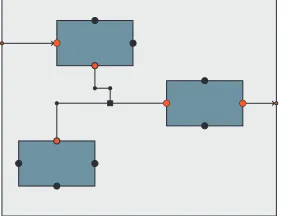
Figure 3: ELADO structure Pins are the connection points for nets. Figure3shows a
sim-ple network. A outer component contains three components. These components are connected by a net. This net is owned by the upper component and associated with pins of the in-ner components. Additional, Figure3denotes other elements of the ELADO structure model. In the mathematical sense, the net between the inner components is a hyper edge. The three parts of the net (called as segments) are ending in a com-mon branch point (shown as smal black rectangle in Figure3). Further, each segment is modeled by segment parts which are delimited by bend points (shown as smal black cicles in Fig-ure3). Apart from the model elements featured above, other classes exist for group representation, annotations and special structure elements.
Besides the structure model, ELADO consists of a visualization model. This part of ELADO is used to store information about the geometry of a network element, its shape as well as layout-specific behaviors. This means for instance, that standardized symbols from various fields of applications can be simply represented. For example in Figure4, the net’s segment representing a bus is drawn by a double line and in Figure3 the component’s pins are located on fixed po-sitions on the component’s shape and all connected pins are colored different. The latter could be a special layout behavior. In addition, each component can contain simple graphics (pictures, lines, text, etc.) as well as store its own layout information such as connection rules and routing behaviors. Therefore, in one application various visual languages could be embedded.
ele-ment is modeled by a class, the application model is an abstract data structure. The data is stored in an associative property tree. Each node in the tree can be identified by a key and owns a value object and a subtree. As indicated in Figure2, diverse types of basic values such as numbers, intervals and time series are implemented in ELADO as derived classes.
In conclusion, ELADO satisfies the requirement of an extendable meta model. The use of the same model for networks as well as for project structure modeling and the appropriate applica-tion data management makes CASTool different from standard drawing tools. As a matter of principle, all applications we develop underlie this model approach. Hence, we call such appli-cationsgraph-base engineering applications. ELADO consists of approx. 65 classes. Based on ELADO, CASTool provides a few class libraries to develop graph-based engineering systems in an efficient way. Some of these are described below.
2.2 Extensibility and Configurability
In order to be able to develop diverse engineering solutions, the system architecture must be designed such that new functionality can be added and existing functionality extended or modi-fied. For this purpose, the framework can be augmented by application-specific services such as special layout methods and engineering components like simulators etc.
Figure 1 shows the extension mechanism embedded into the system architecture. Additional software components can be added dynamically at run time via a defined mechanism. On prin-ciple, every user-controlled communication between components is based on the execution of commands. The use of such a command is based on the fabric pattern [GHJV95] whereas the creation is embedded in the command itself.
Due the abstract application data model (see Section2.1), the handling of special data is more complicated and not high-performing. Therefore, every ELADO object (more precisely every CASTool object) can be decorated with interface objects. An interface object provides specific functions for model data access and manipulation, but can not store data persistently. This is not necessary, since all data can be stored in the application model. The registration of interface objects works in the same way as for commands by registering an alias at runtime.
Beside the system’s extensibility, configuration mechanisms have been implemented within the system (configuration engine in Figure1), which are primarily used for the design of GUI and layout management (in form of layout plans that formulate the calls of individual analysis, layout and evaluation methods) of an application. This can be done by modifying initialization files or, alternatively, by dynamic script interpretation at run time. Currently, interpreters forJavaScript,
2.3 Additional Framework Features
CASTool’s presentation module is responsible for outputting the model data corresponding to the application. To visualize the ELADO structure model and interact with it, a software com-ponent for drawing schematics is included (the presentation engine in Figure1). To deal with ELADO application data, generic dialogs and forms have been developed. For that purpose, dialog elements for base data types are developed including optional GUI elements for addition information (units, bounds, intervals). A dialog generator arranges sets of these line by line on forms. Nodes of the application data tree rendered as tabs. Besides this features CASTool provides data exchange routines (XML formats for data exchange, SVG and pixel formats for schematics) as well as client-server components to run the framework in intranet/internet envi-ronments without visualization, in which case CASTool acts as a layout server.
3 Layout Methods
The framework includes a couple of basic layout methods such as the usual procedures for align-ing selected components and simple routalign-ing methods like rubber band. All these methods work direct on ELADO. Furthermore, some special layout and placement methods (with special data structures) are included. These methods also operate with structure as well as geometry infor-mation and have been developed taking graph drawing techniques into account. Their purpose is to emphasize the structural properties of networks, and they also have to be clear and aesthetical. Moreover, layout methods need to be topologically and geometrically stable to prevent recogni-tion problems during interacrecogni-tions on the part of the user [BP90]. Amongst others, the framework includes the following layout methods:
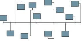
Orthogonal routing: This aids the interactive graphic design of networks by locally adapting the net routing whenever component positions are changed. As a special feature, this method finds long continuous connection parts (buses) and draws them as horizontal or vertical lines.
Figure 4: Bus routing This makes the schemes much easier to read because of the
representation of one main flow. This bus routing method consists of three parts: pattern routing for two point connec-tions, autonomous bus routing and post processing for bus routing. The pattern routing draws two-point connections in a sophisticated way by using a set of defined base patterns. The bus routing handles hyper-edges and embeds them as sub-optimal Steiner-Trees. While the autonomous bus rout-ing disregards collisions, the post processrout-ing optimizes the results by regarding collisions. Figure6shows the bus rout-ing in an application.
Tree layout: This includes techniques that allow to draw networks with tree-like structures. Various basic principles regarding the direction of growth, adjustment and the order of
com-(a) Bottom left tree
A A
A
A A
A A
(b) Tree with star and buses
Figure 5: Various tree layouts
ponents can be selected in accordance with corresponding parameters. The tree layout follows the principle of topological stability. For that purpose, the user can choose the root node of a tree as well as the order of subtrees by graphical interactions. Additional, special network features like stars and busses are supported.
4 Applications
In recent years, various different solutions have been developed on the basis of the domain frame-work presented here. Some of them are briefly described below.
4.1 TOP-Energy - Toolkit for Optimization of Industrial Energy Systems
The main aim of TOP-Energy is to support energy consultants in analyzing and optimizing indus-trial energy supply systems by providing modules for documentation, simulation and evaluation of energy systems with respect to energetic, economic and environmental aspects.
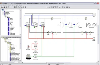
TOP-Energy consists of two major parts: CASTool and a set of modules. The former supplies the services of a modern GUI-application such as module-sensitive dialogs and presentations, flow sheet editing and report generation. Figure6shows the flow sheet editor in TOP-Energy for the modeling of energy supply systems. A flow sheet is TOP-Energy’s visual language to model energy systems and can contain different kinds of energy components. Components represent technical objects (e.g. chiller) as well as non-material objects (e.g. energy rates). The flow sheets are used by a simulator module to calculate energy demands [AWKP04]. The visual language of flow sheets includes some connection rules to connect only pins of the same medium as well as rule definitions of hyper-nets and flow directions. Because of the marginal spatial comprehen-siveness of these systems, a special placement procedure is not necessary. The included local alignment operations and collision detections are adequate. However, strong internal linking structures require an appropriate routing procedure.
Figure 6: Flow Sheet in TOP-Energy
4.2 VotAn - Requirements Engineering Tool for Software of Technical Systems
VotAn is a tool for requirements engineering of software solutions in technical engineering envi-ronments, especially in the field of automation. It provides a model-based approach with focus on a product model. VotAn includes a few well-defined term structures (thesaurus, taxonomy) containing domain-based knowledge for some application areas. Besides product objects, this structure includes terms for functional and non-functional requirements in form of templates, so-called VotAn-Objects. In general, VotAn supports, among other things, the following activities:
• acquisition, specification, structuring, tracing and revision of requirements in a systematic way by further using of standard (third party) software
• adaptable methodical guidance for the structuring of the requirement specification includ-ing their documentation in different forms
• template creation for self-made reusable VotAn-objects
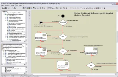
Figure 7: Activity Sequence Scheme in VotAn
of a VotAn-Object that the proxy belongs to, using the framework‘s generic dialogue generation. The conditions in that diagrams are proxies, too. These control the sequence in dependence of a value of a VotAn-Object’s parameter. Additional, some common diagram elements (e.g. message dialogs in form of activities and user controlled branchings in form of conditions) are available. As a result, the user can define wizard-like data administration sequences. Again, these can be stored as templates and reused as domain-specific process model for different projects.
4.3 SwitchLay - Switch Cabinet Layout
Switching stations can be found in modern factories and buildings everywhere. They are utilized as supervisory station to control and observe different technical processes. Electrical/ electrome-chanical engineering systems (ECAD-systems) are often used to design switchboards. As design result, circuit diagrams are mainly developed. But for the physical design of a switchboard they offer no assistance [VSP04].
SwitchLay possesses two methods for layout on the mounting plates of switch cabinets: place-ment and routing. These are quite different layout tasks as in the application descried before. In SwitchLay, a physical layout is required, in which the components have to be full-scale placed, and routing means wiring of cable in a physical environment.
Figure 8: Switch Cabinet Layout Any affinities or incompatibilities
be-tween the electrical devices must be taken into account. Note that the pattern merely describes the basic architecture of the channel frame and the existence of cer-tain rails. During placement, the channel frame needs to be resized depending on space requirements.
The key problem of routing is the decom-position of hypernets. The clamps in-volved in a hypernet must be connected by a tree that branches out only at the clamps. The clamps have limited va-lences for technical reasons. For each hy-pernet, the algorithm forms partial trees, which are successively connected. An extended form of Dijkstra’s algorithm is used [VSP04].
SwitchLay seems to be quite different to applications including logical net-like
structures, but de facto, all SwitchLay components could be modeled by ELADO (see Section
2.1). Consequently, SwitchLay was developed as a prototype based on CASTool to investigate the layout methods and show the layout results. Currently, the routing method is included in a third party ECAD-system.
5 Experiences
We use the described framework in application development since a couple of years. More precisely, we have developed the framework from prototypes, which have been developed in re-search projects. Hence, we used a reactive strategy to develop our framework as a product line infrastructure. This way implicated some necessary redesign processes. As the result, we have now a powerful software basis for application development in the field of graph-based engineer-ing systems. The main approach, the same data model for all applications, has the advantage of using common software components. Especially the GUI components for the ELADO structure model and generic dialogs and forms for the ELADO application model make rapid prototyping possible. Certainly for end products, special GUI elements especially for application data must be implemented. Furthermore, the same date model comprised the data exchange between dif-ferent applications in a native way.
common functionalities in framework libraries and modules.
The system configurability and extensibility necessitate the abstraction level described here. To-gether with the abstract ELADO application data, the system’s complexity increases, which is why particular attention had to be paid to system performance.
In order to cover areas of usage which are as large as possible, the system has been developed to run on various system environments by means of platform-independent libraries. All framework classes are written in C++ using open-source third party libraries such as wxWidgets [SHC05] and Apache Xerces. So far, the framework, including layout methods, comprises about 850 classes and approx. 300,000 lines of code.
6 Related Works
With the increasing popularity of UML in the end of 1990s, the use of visual techniques and graph-based tools increased. Therefore, a large number of (Meta)CASE tools have been devel-oped. The main objective of these systems is to provide software modeling techniques as well as tools for source code generating. Independently of that, many systems for modeling, pro-gramming as well as simulating of technical applications with visual modeling techniques (e.g. LabView and Matlab Simulink) are widely used. These systems are designed for non-application specific languages and require special user knowledge.
In contrast, CASTool offers the development of software systems for engineering applications with user-defined, domain-specific, visual languages and, therefore, provides the modeling of technical systems in an easier way. This and the possibility to extend application-logic (e.g. sim-ulators) enables the end-user to deal with complex issues in a domain-specific environment. Besides many visual modeling tools [JM03], a few frameworks for such applications have been built up to date. The Graphical Modeling Framework (GMF [N06]) is such a framework. GMF is a bridge between the Eclipse Modeling Framework (EMF) and the Graphical Editing Frame-work (GEF). Another frameFrame-work for the development of graph-based applications is UPGRADE
[BJSW02] that is not only used to develop software engineering tools too. It provides many of
the framework features descried above (e.g customizability, extensibility as well as convenient layout methods). GMF provides a number of visual editors for the application development pro-cess. In contrast, CASTool contains only an editor for tree-structured configuration files and a graphical editor to create component appearances. To describe connection rules, CASTool in-cludes a declarative way in form of configuration files. This is rather weak compared to the visual languages provided by GMF and PROGRES. A visual description language for design rules was developed in [FPA05] and will be integrated in the framework by future works.
7 Conclusion
The framework described above enables custom-made engineering systems to be produced effi-ciently. The chosen approach of using a lower abstract meta model enables the implementation of many common functionalities for graph-based engineering systems in the software basis. The simple adaptability of the system supports the supply of ergonomic user interfaces and enables individual configurations. As a result, changing user requirements can easily be taken into ac-count in the latter phases of application development and even after the system has been com-pleted. The presented solutions demonstrate that the system approach can be used for application development, rapid prototyping as well as basis for further frameworks.
One can easily imagine that CASTool can be used not only for engineering systems but also for other similar systems (related to the data model and required system functionalities) of different domains. In particular, the possibility of being able to generically add functionality to the system and to integrate this functionality into the overall architecture opens up a broad sphere of appli-cations for CASTool.
Future work will involve evolving research prototypes into products and developing other layout methods as well as searching for new fields of application.
Acknowledgements: The authors are grateful to the Federal Ministry of Economics and Tech-nology of Germany as well as the Federal Ministry of Educations and Research of Germany for the financial support of several projects on this subject.
Bibliography
[AWKP04] E. Augenstein, G. Wrobel, I. Kuperjans, M. Pleßow. TOP-ENERGY -
Computa-tional Support for Energy System Engineering Processes. In Tsahalis (ed.), Proceed-ings of the 1st International Conference ”From Scientific Computing to Computa-tional Engineering”. Volume 3, pp. 1284–1291. Patras University Press, Athens, Greece, September 2004.
[BJSW02] B. B¨ohler, B. J¨ager, D. Schleicher, B. Westfechtel. UPGRADE: A Framework for
Building Graph-Based Interactive Tools. In Mens et al. (eds.),Proceedings Interna-tional Workshop on Graph-Based Tools (GraBaTs 2002). Electronic Notes in Theo-retical Computer Science 72(2). Elsevier, Barcelona, Spain, October 2002.
[BP90] K.-F. B¨ohring, F. N. Paulisch. Using Constraints to Achieve Stability in Automatic
Graph Layout Algorithms. InACM SIGCHI Conference on Human Factors in Com-puting Systems. ACM SIGCHI, pp. 43–51. Seattle, WA, April 1-5 1990.
[BPPS01] T. Bartsch, M. Pleßow, M. Pocher, H.-W. Schmidt. Ein universelles System f¨ur die
Projektierung von Prozeßleitsystemen.ZwF Zeitschrift f¨ur wirtschaftlichen Fabrik-betrieb4(96):205–211, 2001.
[DETT99] G. Di Battista, P. Eades, R. Tamassia, I. G. Tollis.Graph Drawing - Algorithms for
[Dit04] K. Dittert. Softwarearchitekturen: Mythen und Legenden.OBJELTspektrum3:34– 39, Mai/Juni 2004.
[FPPL05] R. Fr¨ohling, M. Pocher, M. Pleßow, A. Lisounkin. Tools for Knowledge Acquisition,
Modeling and Visualization Applied to Process Supervision. In Kr¨uger et al. (eds.),
Industrial Simulation Conference. Pp. 358 – 362. EUROSIS, June 2005.
[GHJV95] E. Gamma, R. Helm, R. Johnson, J. Vlissides. Design Patterns. Addison-Wesley,
January 1995.
[GPS03] B. Goetze, M. Pleßow, P. Scheffler. Level-Layout f¨ur die Generierung grafischer
Dokumentationen in der Leittechnik. ZwF Zeitschrift f¨ur wirtschaftlichen Fabrik-betrieb3(98):97–101, 2003.
[JM03] M. J¨unger, P. Mutzel. Graph Drawing Software. Mathematics and Visualization.
Springer, 2003.
[N06] N. N. The Eclipse Foundation - Graphical Modeling Framework.
http://www.eclipse.org/gmf/, 19.12.2006.
[PP98] M. Pleßow, M. Pocher. Intelligente Editoren - ein innovatives Konzept f¨ur die
Erstel-lung von schematischen DarstelErstel-lungen. In Dassow and Kruse (eds.),Informatik ’98. Pp. 141 – 150. Springer-Verlag, Magdeburg, Germany, September 1998.
[PS89] M. Pleßow, P. Simeonov. Netlike Schematics and their Structure Description.
In Menga and Kempe (eds.), Workshop on Informatics in Indusrial Automation. Pp. 144–163. CICIP, Berlin, GDR, Nevember 1989.
[SHC05] J. Smart, K. Hock, S. Csomor.Cross-Platform GUI Programming with wxWidgets.
Bruce Peren’s Open Source Series. Prentice Hall, USA, 2005.
[STT81] K. Sugiyama, S. Tagawa, M. Toda. Methods for Visual Understanding of
Hierarchi-cal System Structures.IEEE Transactions on Systems, Man and Cybernetics SMC-11(2):109–129, 1981.
[VSP04] W. Vigerske, B. Stube, M. Pleßow. Automatic Wiring in Switch Cabinets. In
Maropoulos and Schaefer (eds.),Proceedings of the 1st International Conference on Electrical/Electromechanical Computer Aided Design and Engineering. Pp. 90–93. The University of Durham, School of Engineering, Durham, UK, November 2004.
[WHA07] G. Wrobel, S. Herbergs, E. Augenstein. TOP-Energy - Ein Framework f¨ur