Numerical simulation of gravity dam seepage field based on UDEC – with Datengxia hydropower
station as an example
Tianyang Liu1*, Wen Zhang1, Chun Tan2,3, ZhifaMa2,3
1 Jilin University, Changchun 130000, China
2 China Water Northeastern Investigation, Design & Research Co, Ltd, Changchun 130000, China
3 Engineering Technology Research Center of Ministry of Water Resource in the Cold Region, Changchun 130000, China
Corresponding Author Email:[email protected]
https://doi.org/10.18280/eesrj.050404 ABSTRACT
Received: 5 October 2018 Accepted: 18 December 2018
With the dam section 28# of Datengxia Hydropower Station in Guangxi Province as an example, this paper uses the software UDEC to study the seepage of the dam foundation rock mass and the stability of the dam foundation rock mass under the impacts of seepage. The dam foundation rock mass consists of continuous gently-dipping weak intercalated layers and intermittent steeply-dipping tectonic fissures. In order to analyze the impacts of the anti-seepage curtain on the anti-seepage of the dam foundation rock mass and the stability of the dam foundation, this paper takes parameters such as the displacement of the key points, the lifting pressure, and the unbalanced force and the plastic yield zone within the model as the criteria for quantitative analysis. The analysis results show that the anti-seepage curtain can effectively isolate the seepage of the dam foundation rock mass, so that the dam foundation rock mass can be maintained stable and undamaged. Finally, by comparing the numerical simulation results with the calculation results of the analytical method, this paper proves the reliability and rationality of this method and shows that it can be used as a reference for analysis in similar projects.
Keywords:
seepage, stability, UDEC, discrete element
1. INTRODUCTION
The migration of groundwater in the fracture network of rock masses plays an important role in various projects. The stability of a dam foundation rock mass is affected by the uplift pressure in the weak intercalated layers, beddings and joint fissures, as the uplift pressure acting on the weak intercalated layers or beddings can offset the weight of the upper rock mass to a certain extent, thereby reducing the anti-sliding force and stability of the dam foundation rock mass. In recent years, many water conservancy projects have conducted supervision on the anti-seepage curtains to reduce the impacts of seepage on the projects. However, it is a challenging and urgent problem as how to analyse whether seepage has any impact on the hydraulic engineering and the effects of the anti-seepage curtain on seepage reduction.
So far, many scholars have studied the seepage of fractured rock masses. At present, considering the research methods and the different fracture media, the fractured rock mass seepage models can be roughly divided into the equivalent continuum model, the discrete fracture network model and the double medium model, among which, among them, the equivalent continuum model simulates the seepage in the model based on the traditional porous media analysis under the boundary conditions. [1] studied the impact of the rock mass fissure width on seepage based on the equivalent continuum model; [2] established an equivalent continuum seepage and stress coupling model to conduct coupling analysis on the seepage and stress of the fractured rock mass. However, the equivalent continuum model is only applicable to the analysis of media
with dense fracture distribution. For sparse distribution of fractures, other methods should be selected for research. The discrete fracture network model is a structure formed by the intersection of fractures in space. It ignores the permeability of the rocks and assumes that seepage only occurs in the fracture network. [3-5] established a fracture network model for crack grading, and analyzed the pattern of fissure water during seepage. [6] explained the mechanical effects of seepage on fractured rock masses. [7-12] analysed the rock mass fracture network and analyzed the law of seepage in discrete media. However, in the discrete model analysis, it was impossible to simulate the distribution of each fracture and the hydraulic characteristics of seepage, so they could only analyze the macroscopic law on the generalized basis. The double medium model considers rock as a continuous medium, which is composed of pores and fractures, so they established the equations according to the flow changes of seepage in the two media. [13] etc. analyzed the finite element solution of seepage through the double medium model. [14] analyzed the seepage with the double fracture system and achieved corresponding results. Although the double media model is more in line with the reality, the amount of calculation is larger, which undoubtedly increases the cost of analysis.
The Datengxia Gorge Water Conservancy Project contains a complex structural plane system with obvious discontinuous fractures. Since the discrete element method has so far been the only way to analyze the discrete medium model, after fully considering the engineering geological characteristics and simplifying and modelling the complex structures, we used the software UDEC to conduct this study.
Environmental and Earth Sciences Research Journal
Vol. 5, No. 4, December, 2018, pp. 101-1062.OVERVIEW OF THE DATENGXIA HYDROPOWER STATION PROJECT
The research site selected in this paper is the dam section 28# of the Datengxia Hydropower Station. The main dam of the Datengxia Hydropower Station is located near the Datengxia Gorge outlet of the Qianjiang River, the main stream of the Xijiang River, in the Pearl River Basin. The reservoir is Y-shaped. The normal water level of the reservoir is 61.00m, and the corresponding storage capacity is 28.13×10⁸m3. The flood control water level is 44.00m. The
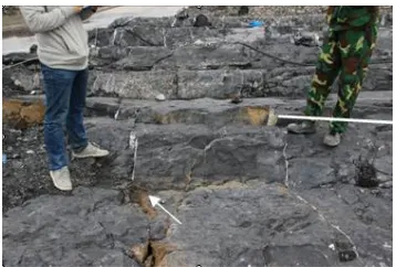
lithology of the dam foundation is the lower Devonian clastic sedimentary rock tidal facies, consisting of argillaceous limestone, limestone and dolomite. The limestone and dolomite are mainly dissolved and weathered, and the surface part is strongly weathered along the cracks and beddings. A number of weak intercalated layers that are developed on site, with occurrences basically consistent with those of the rock formation. The overall picture of the study area is shown in Figure 1.
Figure 1. Overall picture of the working plane at dam section 28#
The dam foundation has a strong geological structure with complex geological conditions. There are a large number of cracks developed on site with different characteristics, and the groundwater in the rock body circulates frequently. In general, most of the site joints have small openings and are characterized by shearing, dominated by steep dips. The cracks on site are divided into two groups. The average tendency of one dominant group intersects with the axis of the dam at a small angle, and the other with the dam axis at a larger angle. The cracks that tend to intersect with the dam axis at a large angle have great impacts on the stability of the dam foundation and can easily form a collapse surface that leads to the failure of the dam foundation rock mass. In addition, a large number of joints that do not cut the interface between the weak layer and the formation are exposed in the vicinity of the interface. The development status is shown in Figure 2.
Figure 2. Joint fissures on site
Per the analysis of the fracture data obtained from the field investigation, the average spacing of the fractures near the
surface at the gate section is about 2m, and the downstream rock mass adopts the fracture spacing data near the gate section. The weak intercalated layers have an inclination of about 11°, and the fissures on site have an inclination of about 79° towards the upstream. Both are nearly vertical.
3.SEEPAGE CALCULATION
3.1 Modelling
UDEC is a two-dimensional discrete element program that handles discontinuous media. It is often used to simulate the response of a discontinuous medium (such as a fractured rock mass) under load. In the UDEC, it is assumed that blocks are impermeable, so it can simulate the seepage and mechanics-seepage coupling of the joints in the model. In UDEC, the fluid is treated as viscous flow between parallel plates. The mechanical deformation of the joints affects the permeability of the rock mass, and at the same time, the mechanical properties of the joints are also affected by the water pressure. The seepage of a flat and smooth single fracture is usually studied based on the fracture cubic law. Suppose the rock mass is a parallel plate model, with a fracture width of the constant a, and the seepage in the fracture conforms to the Navier-Stokes equation, i.e.
,
1
i
i i i ij
u
F
p
u
t
=
−
+
(1)where, μi is the flow rate component; Fi is the acting force; ρ
is the density of water; p is the water pressure; υ is the kinematic coefficient of viscosity, whose value is related to temperature. Since the deep flow in the fractures generally has a small rate, the flow head can be ignored. And when the flow rate is small, the water flow in the model should be in the laminar conditions. Therefore, in the end we can obtain the column vector through the fracture based on the above conditions:
3 2
2
12
a
x a
ga
q u dz J
−
=
=(2) It can be seen from equation (2) that the flow rate q passing through the equal-width slit is proportional to the third power of the slit width a.
in the direction y are fixed. When the reservoir is filled with water, water pressure will be applied to the upstream, downstream and floodgate surfaces.
According to the on-site fracture data, the average spacing of the fractures near the surface close to the gate section is taken as the average spacing of the surface rock mass fractures, i.e. 2m. Since the deep rock mass has little impact on the stability of the dam foundation rock mass, the deep fracture spacing is set at 10m. In the seepage simulation, it is assumed that the bottom and sides of the dam foundation are impervious to water, and that the water storage level is normal. There are two cases – one with a curtain and one with no curtain, which are respectively considered and also compared. In the dam foundation sensitivity study, three working conditions are simulated – the normal water level, the design flood level, and the check flood level, all with a curtain. The water levels under the three conditions are shown in Table 4.
Figure 3. Numerical model of dam section 28#
Table 1. Shear parameters of the dam foundation rock strata
Rock
number Weathering state c′Pa) (M f
Deforma tion modulus
Modulu s of elasticit
y
D1y1-3 moderate 0.82 0.60 5 8
D1y1-2 moderate 0.85 0.62 8 12
D1y1-1 moderate 0.80 0.60 5 8
D1n13-3 moderate 0.79 0.58 3 4
D1n13-2 Weak 1.45 0.64 6 8
D1n13-1 Weak 1.63 0.71 8 12
D1n12 Weak 1.72 0.75 9 8
D1n11-7 Weak 1.46 0.65 5 8
Table 2. Physical and mechanics parameters of the structural plane
Structural
plane type (Pa/m) Kn (Pa/m) Ks (°) φj ϲj (Pa) σ t
j (Pa)
crack 1×10¹¹ 1×10¹⁰ 26.5 0 0
D1n11-7 1×10¹¹ 1×10¹⁰ 14.5 1.5×10⁴ 0
D1n13-1~D1n13-1 1×10¹¹ 1×10¹⁰ 15.6 2×10⁴ 0
D1y1-1 1×10¹¹ 1×10¹⁰ 17.7 4×10⁴ 0
(D1y1-2) 1×10¹¹ 1×10¹⁰ 16.7 3×10⁴ 0
Stratigraphic
boundary 1×10¹¹ 1×10¹⁰ 24.2 1.5×10⁵ 0
The curtain 1×10¹¹ 1×10¹⁰ 42 7.5×10⁵ 2×10⁶
Fault
boundary 1×10¹¹ 1×10¹⁰ 0 0 0
The bottom
of the dam 1×10¹¹ 1×10¹⁰ 42 7.5×10⁵ 0
Table 3. Hydraulic parameters of the structural plane
Structural plane type kj (Pa-1s-1) a0 (m) ares (m)
Structural fissure 83.3 2×10⁻³ 1×10⁻³
Weak intercalation 83.3 2×10⁻³ 1×10⁻³
Stratigraphic boundary 83.3 2×10⁻³ 1×10⁻³
The curtain 0 0 0
Fault boundary 83.3 2×10⁻³ 1×10⁻³
The bottom of the dam 83.3 2×10⁻⁴ 1×10⁻⁴
Table 4. Water levels under the three operating conditions
Normal water level
/m
Design flood level
/m
Check flood level
/m The upstream
water level 61.00 61.00 61.00
The downstream
water level 22.71 46.41 49.2
3.2 Results analysis
3.2.1 Seepage calculation
In order to analyze the impacts of the anti-seepage curtain on the seepage, this paper simulates dam section 28# based on the above boundary conditions, and analyzes the seepage with and without the curtain. The seepage field obtained is shown in Figure 4.
(a) Seepage of dam section 28# with no curtain
(b) Seepage of dam section 28# with a curtain
Figure 4. Seepage of dam section 28#
anti-seepage curtain has a great impact on the anti-seepage of the dam foundation.
3.2.2 Uplift pressure calculation
In order to further analyze the impacts of the anti-seepage curtain on the seepage of the dam foundation, this paper analyses the uplift pressure of the structural plane of the dam foundation. In the calculation, five monitoring points are set at the bottom of the dam foundation to monitor the uplift pressure in the model, denoted as A, B, C, D and E. The layout of the monitoring point is shown in Figure 5, and the same is also arranged for the monitoring points in the case with a curtain.
Figure 5. Layout of the seepage monitoring points
Figure 6 shows the comparison of the uplift pressure at different monitoring points of dam section 28# with and without curtain. As can be seen, before the anti-seepage curtain, the maximum uplift pressure of all the key monitoring points in the model is 0.41MPa, the minimum value 0.34MPa, and the average value 0.37MPa. After the anti-seepage curtain is set up, the maximum uplift pressure in the model is 0.29 MPa, the minimum value 0.2 MPa, and the average value 0.24 MPa, indicating a reduction of 0.13MPa (34.1%). Such significant reduction of uplift pressure in the structural plane further proves the great impact of the anti-seepage curtain on the seepage of the dam foundation.
Figure 6. Comparison of the uplift pressure in dam section 28# with and without curtain
3.2.3 Verification by the analytical method
In order to verify the accuracy of the numerical simulation results, the uplift pressure of the upstream sliding surface and the lower sliding surface is calculated using the analytical method, and it is also monitored at the same positions in the numerical simulation model. The comparison chart is shown in Fig. 7, where the red line part indicates the result of uplift pressure simulated by software, and the black line part the result of the uplift pressure calculated by the analytical method.
It can be seen from the figure that in the case with curtain, the maximum uplift pressure of the upstream sliding surface obtained by numerical simulation is 510.9 KPa, which is smaller than the analytically calculated 520KPa by 1.75%; that
of the interface between the upstream and downstream sliding surfaces obtained by numerical simulation is 260 KPa, which is larger than the analytically calculated 247.1KP by 5.2%; that of the downstream sliding surface obtained by numerical simulation is 287.9KPa, greater than the analytically calculated 274.5 KPa by 4.88%, and that at the exit of the downstream sliding surface is 84.98 KPa, which is greater than the analytically calculated 77.5kg by 9.65%. The numerical simulation results of the uplift pressure at the special points are not much different from those calculated by the analytical method, indicating that the numerical simulation results are credible.
(a) Comparison of the uplift pressure in dam section 28# with no curtain
(b) Comparison of the uplift pressure in dam section 28# with curtain
Figure 7. Comparison of the uplift pressure in dam section 28#
3.3 Stability analysis of the dam foundation
A gravity dam will be affected by groundwater seepage after being completed and put into service. According to our previous analysis, there is indeed great uplift pressure at the bottom of the dam foundation, which is a potential hazard to the dam foundation. Therefore, in order to verify the safety of the floodgate, it is necessary to study the stability of the dam foundation.
The author clears the displacement field after the settlement of dam section 28# is stabilized and then applies the external load to solve the problem. Through analysis of the unbalanced force curve of the model, it can be seen that as the calculation time step increases, the maximum unbalanced forces of the three working conditions all tend to zero in the end, which means that the model can eventually reach the stable equilibrium state.
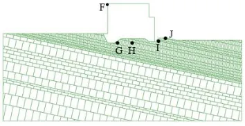
According to the geological characteristics of the site, the distribution of the structural planes and the force conditions, the gate chamber may be turned over, the bottom of the dam foundation may experience surface sliding or deep sliding, and the downstream may collapse or cut out, so the monitoring points are mainly concentrated in the gate chamber and the bedrock at the bottom of the floodgate, which are the positions that are most prone to damages. In the calculation, 5 monitoring points different from the previous ones are arranged at the above positions to monitor the displacement changes in the directions x and y. To better present the specific locations of the key monitoring points and the following descriptions, the five key monitoring points are denoted as F, G, H, I and J, respectively, as shown in Fig.8.
Figure 8. Layout of the displacement monitoring points Figure 9 is a graph showing the displacement deformation of each monitoring point with the variation of the time step under three working conditions. From Figure 8, it can be seen that the displacements of each point at the directions x and y all converge at the three different water storage levels. At each water level, the point F, i.e. the gate chamber, has the greatest displacements in both the directions x and y. Take the displacements of the point F for example. From the curve, it can be seen that the x-direction displacement of the gate chamber tends to be 9.0×10⁻³m and the y-direction
displacement -1.5×10⁻³m under the normal water storage level;
under the design water level, the x-direction displacement of the gate chamber tends to be 8.0×10⁻³m, and the y-direction
displacement -3.6×10⁻³m; and under the check flood level, the
x-direction displacement of the gate chamber also tends to be 7.8×10⁻³m, and the y-direction displacement -4.0×10⁻³m.
From the normal water level to the check flood level, the upstream water level remains unchanged, while the downstream level is rising. Therefore, the hydrostatic pressure of the downstream water body towards the left on the gate chamber is getting larger, so is the hydrostatic pressure of the downstream water body on the downstream bedrock, and accordingly, the x-direction displacement of the entire dam towards the right is reduced, while the y-direction displacement is increased.
In summary, the displacements of the gate chamber and the dam foundation rock mass under the three conditions are all convergent, with very small deformations (on the millimetre level). There is no plastic zone in the model, and the dam functions normally. It also shows that the model has finally
reached a stable equilibrium state. Therefore, dam section 28# is safe under the three water storage levels.
(a) Displacement with the variation of the time step at the normal water storage level
(b) Displacement with the variation of the time step at the design water level
(c) Displacement with the variation of the time step at the check flood level
Figure 9. Displacement deformation of the monitoring points with the variation of the calculated time step
4.CONCLUSIONS
This paper carries out simulation and analysis of the dam section 28# of Datengxia Hydropower Station and obtains the following conclusions.
(1) This paper presents a method for analyzing the seepage of the dam foundation rock mass to determine if it will affect the project. It provides some reference for similar projects.
(2) The anti-seepage curtain has obvious barrier effect on seepage. The numerical simulation results show that after the anti-seepage curtain is set up, the flow and the uplift pressure are obviously reduced, indicating that the anti-seepage curtain has a great effect on the seepage control of the dam.
force curve is convergent. Therefore, it can be seen that the dam foundation is stable under these three water levels.
(4) Through comparison, it is found that the uplift pressure of the upstream and downstream sliding surfaces calculated by the analytical method are close to that obtained by numerical simulation, proving that the numerical simulation method adopted in this paper is credible.
REFERENCES
[1] Gao Y, Ye X, Xia Q. (2016). Numerical simulation of single fracture seepage based on equivalent continuum model. Groundwater 38(5): 40-43. http://doi.org/10.3969/j.issn.1004-1184.2016.05.016 [2] Wang Y, Su BY, Xu ZY. (1998). Full coupling analysis
of seepage and stress in equivalent continuous fractured rock mass. Journal of Hohai University (2): 26-30. http://doi.org/10.3321/j.issn:1000-1980.1998.02.005 [3] Wang D, Shen ZZ, Tao XH. (2012). Three-dimensional
finite element analysis and safety assessment for seepage field of a tailings dam. Journal of Hohai University (Natural Science Edition) 40(3): 307-312. http://doi.org/10.3876/j.issn.1000-1980.2012.03.011 [4] Chen SK, Yan J, Li JM. (2011). Seepage field 3D finite
element simulation of concrete faced rockfill dam under failure condition of vertical fracture. Rock and Soil Mechanics 32(11): 3473-3478, 3486. http://doi.org/10.3969/j.issn.1000-7598.2011.11.045 [5] Liu J, Xie DS. (2011). Development status of seepage
control theory for rock DAMS in China. Journal of Geotechnical Engineering 33(5): 714-718. http://doi.org/10.3354/cr00999
[6] Wang EZ, Han XM, Huang YZ. (2003). Nonlinear
seepage mechanism of low-permeability rock. Rock and Soil Mechanics (S2): 120-124, 132.
[7] Wang EZ, Sun Y, Huang YZ, Wang HM. (2002). 3-D seepage flow model for discrete fracture network and verification experiment. Chinese Journal of hydraulic
Engineering (5): 37-40.
http://doi.org/10.3321/j.issn:0559-9350.2002.05.008 [8] Chai JR, Li SY, Wu YQ. (2000). Research on
multiple-level fracture network modelfor. coupled seepage and stress fields in rock mass. Chinese Journal of Rock Mechanics and Engineering (6): 712-717. http://doi.org/10.3321/j.issn:1000-6915.2000.06.006 [9] Chai JR. (2000). On Mathematical model for coupled
seepage and temperature field in concrete dam. Chinese Journal of Hydroelectric Power (1): 27-35. http://doi.org/10.3969/j.issn.1003-1243.2000.01.005 [10] Chai JR. (2000). Calculation of fracta dimension of
fractured rock mass by monte-carlo analogy technique. Hydrogeology Engineering Geology (2): 12-13. http://doi.org/10.3969/j.issn.1000-3665.2000.02.004 [11] Wang EZ. (1993). Network analysis and seepage model
of rock mass fractures. Chinese Journal of Rock Mechanics and Engineering (3): 214-221.
[12] Yang YY, Zhou WY. (1991). Seepage-damage coupling analysis model of fractured rock mass and its engineering application. Chinese Journal of Hydraulic Engineering (5): 19-27, 35. http://doi.org/10.3321/j.issn:0559-9350.1991.05.003
[13] Zhang YK. (1983). Seepage model of fissure-karst aquifer double media and ritz finite element solution. Engineering Investigation (4): 57-62, 68.