Available online through
ISSN 2229 – 5046MAGNETO-HYDRODYNAMIC COUPLESTRESS COSINE FORMCONVEX CURVED PLATES
SYED ARISHIYA NASEEM FATIMA
1, TRIMBAK BIRADAR
2,
S. T. FATHIMA*
3AND HANUMAGOWDA B.N
41Department of Mathematics,
K. C. T College of Engineering, Gulbarga-585104, India.
2Department of Mathematics,
Sharnbasveshwar College of science, Gulbarga-585103, India.
3,4Department of Mathematics,
Reva University, Bangalore-560064, India.
(Received On: 25-06-16; Revised & Accepted On: 19-07-16)
ABSTRACT
O
n the basis of Stokes couplestress fluidmodel together with the hydromagnetic flow the study of MHD-couple stress cosine curved plates is studied and Modified Reynolds equation has been derived which is applied to the study of squeeze film characteristic including the non-Newtonian hydromagnetic effects. According to the results the combined effect of couplestresses and external magnetic fields provide an increase in the load capacity and the response time as compared to the classical Newtonian hydrodynamic convex curved plates.Keywords: convex curved plates, cosine function,couple-stress fluid, Magnetic field.
1. INTRODUCTION
In recent years, the characteristic of Magneto-hydrodynamics (MHD) in flow analysis are important for many engineering and industrial applications. The MHD bearings with conducting fluids possess the high thermal-conductivity and high electrical-thermal-conductivity features over the conventional bearings. The squeeze film lubrication for different configuration of bearings under the action of transverse magnetic field has been discussed by several authors [1-6].
It is known that, the theory of couplestress fluid by Stokes [7-12] is a generalization of viscous fluid theory with couple stresses and body couples. Couplestress fluids are consequence of the assumption that, the interaction of one part of the body on another across a surface is equivalent to a force and momentum distribution. It consists of rigid randomly oriented particles suspended in a viscous medium such as electro-rheological fluids and synthetic fluids. The MHD bearings with conducting fluids possess numerous advantages over the conventional bearings.
Recently, Lin et al. [13] studied hydromagnetic non-Newtonian cylindrical squeeze film and its application to circular plates by derivation of modified lubrication equation. They found that the improved characteristics are further emphasized for circular plates operating with a larger magnetic field parameter and non-Newtonian parameter.
The MHD conducting couplestress squeeze-film characteristics of cosine form convex curved plates has not been studied so far. Hence, in this paper an attempt has been made to study the conducting couple stresses on the MHD squeeze-film characteristics of cosine form convex curved plates. Expressions for the MHD squeeze-film pressure, load carrying capacity and the time height relation are obtained.
Corresponding Author: S. T. Fathima*3
2. MATHEMATICAL FORMULATION OF THE PROBLEM
Figure-1: The physical configuration of convex curved plates in the presence of transverse magnetic field.
Figure.1 shows the squeeze film geometry between the cosine form convex curved plates. The film thickness h for the
squeeze film can be generated by the form of a cosine function
h
h
0d
1 cos
x
L
π
=
+
−
.In the equation, L is thelength of the plates, d is the amplitude of the cosine function, and
h
0is the minimum film thickness. At the centralposition: x = 0, the film thickness is equal to the minimum film thickness
h
0. At the edge position:2
L
x
=
, the filmthickness is equal to the sum of the minimum film thickness and the amplitude
h
0+
d
. A uniform transverse magnetic fieldB
0 is applied to the bearing in theZ
-direction as shown in the above Figure1.It is assumed that the fluid film is thin, the body forces and the body couples are negligible.Under the usual assumption of hydromagnetic lubrication theory applicable to thin films and Stokes theory for couplestresses, the continuity equation and the Magneto-hydrodynamic (MHD) momentum equation in Cartesian form becomes
2 4
2 0
2 4
u
u
p
B u
x
z
z
µ
∂
−
η
∂
−
σ
=
∂
∂
∂
∂
(1)0
p
z
∂
=
∂
(2)0
u
w
x
z
∂
+
∂
=
∂
∂
(3)Where 0
0
M
M
h
=
and1/ 2
0 0 0
M
B h
σ
µ
=
is the Hartmann number.The third term in Eq.[1] is a Lorentz body force coming from
J B
y 0 under the assumption that the induced magneticfield is much less than the applied magnetic field as described by Kuzma [14]. Then, from Ohm’s law the axial current
density becomes
J
y=
σ
B u
0 . Therefore the termσ
B u
02 appears in the Eq. [1].h0 h
z
x
d(1-Cosπx/L)L/2 V
The relevant boundary conditions for the velocity components are
i) At the upper surface z=h
0(
)
u
=
no Slip
2
2
0
u
y
∂
=
∂
(
Vanishing of couplestresses
)
(4a)
(
)
w
= =
V
dh dt SqueezingVelocity
(4b)ii) At the lower surface z=0
0(
)
u
=
no Slip
2
2
0(
)
u
Vanishing of couplestresses
y
∂
=
∂
(5a)0
w
=
(5b)Where
M
0=
B h
0 0(
σ µ
)
1 2 is the Hartmann number.The solution of equation (1) subject to the boundary conditions eqns. (4) and (5) is given by
2 2
2 0
2 2 2
0
(2
)
(2
)
1
2
2
1
(
)
2
2
A
z
h
B
z
h
B Cosh
A Cosh
h
p
l
l
u
Ah
Bh
M
x
A
B
Cosh
Cosh
l
l
µ
−
−
∂
= −
−
+
∂
−
(6)Substituting (6) in (3) and integrating across the film thickness h gives the modified form of Reynolds equation 2
0
0
( , ,
)
h
p
dh
f h l M
x
µ
x
dt
∂
∂
= −
∂
∂
(7) Where 2 20 2 2 2
0
1
2
( , ,
)
tanh
tanh
2
2
l
B
Ah
A
Bh
f h l M
h
A
l
B
l
M
A
B
=
−
−
+
Introducing non-dimensional quantities, the expressions for the pressure distribution and the load-supporting capacity in dimensionless form are
3
* * * * 0
2
0 0 0
2
,
,
,
,
(
/
)
i
x
h
l
ph
d
x
h
l
p
e
L
h
h
L
dh dt
h
θ
δ
µ
=
=
=
=
=
−
* * * 0* *
(
, ,
)
1
p
F h l M
x
x
∂
∂
= −
∂
∂
(8)* *2 * * *2 * *
* * *
0 2 *2 *2 * * * *
0
1
( , ,
)
l
B
tanh
A h
A
tanh
B h
F h l M
h
M
A
B
A
l
B
l
=
−
−
+
{
}
* *1
1 cos(
)
h
= +
δ
−
π
x
The pressure conditions are:
p
*=
0
at *1
2
x
= ±
and **
0
dp
dx
=
at*
0
x
=
.Integrating (8) and using the pressure conditions, one can obtain
*
*
* *
* * 0
1/ 2
(
, ,
)
x
x
p
dx
F h l M
= −
∫
*
1/ 2 *
* * * * 0
(
, ,
)
xx
p
dx
F h l M
=
∫
Integrating the film pressure, one can obtain the load-carrying capacity / 2
/ 2
L
L
W
b
pdx
−
=
∫
(10)where b denotes the width of the curved plates. The non-dimensional form of load supporting capacity is given by 1/ 2
3
* 0 * *
3
1/ 2
(
)
h W
W
p dx
L b
dh dt
µ
−=
=
−
∫
(11)After performing the integration, one can obtain the non-dimensional load capacity.
*
1/ 2
1/ 2 *
*
* *
* * 0 1/ 2 x
(
, ,
)
x
dx
W
dx
F h l M
−
=
∫
∫
(12)
The non-dimensional form of squeeze film time is given by
𝑇𝑇∗=𝑊𝑊ℎ02𝑡𝑡
𝜇𝜇𝐿𝐿3𝑏𝑏 (13)
The elapsed time required for the upper curved plate to approach the lower plate is given by
* *
0
1/ 2
1 1/ 2 *
*
* * *
0 * *
0
1/ 2 x
(
, ,
)
h
x
dx
T
dx dh
F h l M
−
=
∫
∫ ∫
(14)
For T*,
h
*=
h
0*+
δ
{
1 cos(
−
π
x
*)
}
.Using the numerical method of integration, the film pressure (9), the load capacity (12) and the elapsed time (14) can be calculated.
3. RESULTS AND DISCUSSIONS
The effect of MHD on the conducting couplestress fluid lubrication between convex curved plates is observed and the squeeze film characteristics are analysed with respect to the non-dimensional parameters namely the Hartmann number
* 0
M
and conducting couplestress parameterl
*.3.1 Squeeze film pressure:
Figure 2, 3 represents the variation of non-dimensional
p
*with horizontal coordinate 𝑥𝑥∗ for different values ofl
* and𝑀𝑀0. It is observed that effect of couplestress is to enhance the pressure at the centre in the presence of magnetic field as
compared to Newtonian case. Increase in p is more pronounced for larger values of 𝑙𝑙∗. The dotted lines represents the non magnetic case, and solid lines represents the magnetic case. It is pragmatic that effect of magnetic field is to enhance the pressure as compared to non-magnetic case.
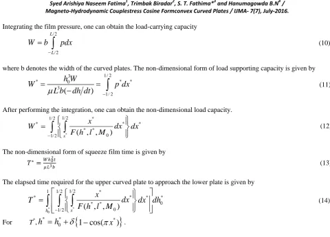
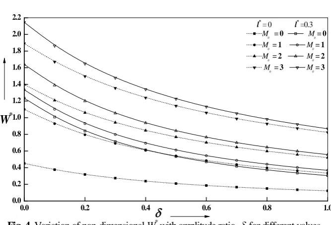
3.2 Load carrying capacity:
Figure.4, and 5 shows the variation of non-dimensional
W
*with amplitude ratio δ for different values of 𝑙𝑙∗ and 𝑀𝑀 0. Itis seen that effect of magnetic field is prominent for increasing values of magnetic parameter
M
0in presence of couplestress fluid. It is observed that with the increasing values of 𝑙𝑙∗ and 𝑀𝑀0 there is significant increase in the load carrying capacityW
∗. The effects are more pronouncedin convex curved plates for CCSF (conducting couplestress fluids) in the presence of transverse magnetic field. The increase in W is more evident for larger values of 𝑙𝑙∗.3.3 Non-dimensional Squeeze film time:
Figure 6, and 7 represents Variation on non-dimensional squeeze film time
T
*withh
0* for different values of 𝑙𝑙∗ and𝑀𝑀0.It is observed that with the increasing values of 𝑙𝑙∗ and 𝑀𝑀0 there is significant increase in squeeze film time
T
*. It isThe effect of couplestress effect in the presence of transverse magnetic field on the squeeze film characteristics is evaluated by relative percentage difference. The increase in the non-dimensional load carrying capacity
R
W∗ and thenon-dimensional squeeze film time
R
T∗ are defined by(
)
{
}
*
* * *
100
couplestress Newtonian Newtonian
W
R
=
W
−
W
W
×
And *
{
(
)
}
* * *
100
couplestress Newtonian Newtonian TR
=
T
−
T
T
×
The values of
W
R
∗ andR
T∗are listed in Table. 1 for various values ofM
0,l
∗
. It is clear that an increase of nearly
4.6%, 24.6% in
W
∗andT
∗is observed forl
∗=
0.2
andM
0=
2
. It is seen that the relative difference in loadW
R
∗isquite significant for increasing values of
l
∗. Further the effect ofl
∗
clearly indicates the increasing values of relative squeeze film time
R
T∗ indicating the enhanced performance characteristics.4. CONCLUSION
The study of Magneto-Hydrodynamic Couplestress Cosine form Convex Curved Plates is studied on the basis of Stokes couplestress fluid model together with the hydromagnetic flow equations Modified Reynolds equation has been derived and the following conclusions are made.
1. The non-dimensional Pressure, load carrying capacity and squeeze film time increases for the couple stress lubricants as compared to the corresponding Newtonian case.
2. The increasing values of magnetic parameter 𝑀𝑀0 is to increase the performance characteristics of conducting cosine form Convex Curved Plates.
3. The relative load carrying capacity and squeeze film time increases with increasing values of couplestress parameter as shown in Table.1
2. Furthur it is observed that the squeeze film time is significant for increasing values of couplestress parameter
𝑙𝑙∗ and magnetic parameter 𝑀𝑀 0 .
NOMENCLATURE
0
B
Applied magnetic field in thez
−
directionH
Film thicknessL length of the plates,
d amplitude of the cosine function b width of the curved plates
0
h
Minimum film thickness
0
h
∗ Dimensionless film thickness after time∆
t
s
h
Stochastic film thickness0
M
Magnetic Parameter
1/ 2
0 0
( )
B h
σ
µ
=
l
Couplestress fluids1 2
η
µ
l
∗ Dimensionless parameter0
2
l
h
𝑢𝑢, 𝑤𝑤 Velocity components in film region
𝑥𝑥, 𝑦𝑦, 𝑧𝑧 Local Cartesian co-ordinates
*
p
Dimensionless pressure3 0 2
(
/
)
ph
L
dh dt
µ
=
−
T
∗ Dimensionless time of approach 2 0 3h Wt
L b
µ
=
V
Squeezing Velocitydh
dt
−
*
W
Dimensionless load carrying capacity3 0 3
(
)
h W
L b
dh dt
µ
=
−
GREEK SYMBOLS
σ
Conductivity of fluidσ
Standard deviationη
Material constant responsible for couplestressµ
Lubricant viscosityξ
Random variableREFERENCES
[1]. W.F.Hughes, “The magnetohydrodynamic Finite Step Slider bearing,” Journal of fluids engineering, Trans. ASME, series D, vol.85, no.1, (1963), pp.129-135.
[2]. W. F. Hughes and R. A. Elco, “MHD lubrication flow between parallel rotating disks, “Journal of Fluid Mechanics, vol. 13, no.1, (1962), pp. 21-32.
[3]. D.C. Huzma, “The Magneto-hydrodynamic parallel slider bearing,” Journal of Fluids engineering, Trans. ASME, series D, vol.87, (1965), pp.778-780.
[4]. D. C.Kuzma, E. R. Maki ,and R. J.Donnely, “The MHD squeeze film,” Journal of Fluid Mechanics, vol.19, no. 3, (1964), pp. 395-400.
[5]. W. F.Huges and R.J. Elco, “Magnetohydrodynamic journal bearing,” Journal of American Rocket society, vol.32, (1962), pp.776-778.
[6]. J. R. Lin, “Magneto-hydrodynamic squeeze film characteristics between annular plates,” Industrial Lubrication and Tribology, vol. 53, no. 2, (2001), pp.66 - 71.
[7]. V.K.Stokes, “Couple stresses in fluids,” Physics of Fluids, vol.9, (1966), pp.1709-1715.
[8] NaduvinamaniN.B. and Siddanagouda A., Combined effects of surface roughness and couple stresses on the squeeze film lubrication between porous circular steppedplates, Jl. of Engg. Trib., 221(J4), (2007) 525. [9] Naduvinamani N.B and. PatilS.B., Combined effects of surface roughness and couple stresses on the static and
dynamic behaviour of squeeze film lubrication of porous journal bearings, Tri.-Materials, Surf. and Interfaces, 1, N(3), (2007), 145.
[10] Naduvinamani N.B., Hanumagouda B.N. and Syeda Tasneem Fathima., Combined Effects of MHD and Surface Roughness on Couple-Stress Squeeze Film Lubrication between Porous Circular Stepped Plates, Trib. Intl., 56 (2012),19.
[11] Lin J.R., Chu L.M, Hung C.R. and Wang P.Y, “Derivation of two-dimensional couplestress hydromagnetic squeeze film Reynolds equation and application to wide parallel rectangular plates”, Meccanica. 48(1), (2012). [12] Lin J.R., Chu L.M., Liang L.J. and Lee P.H., Derivation of a modified lubrication equation for hydromagnetic
non-Newtonian cylindrical squeeze films and its application to circular plates, J.Eng. Math .77, (2012), 69. [13].Lin J.R., Chu L.M., Liang L.J. and Lee P.H., “Derivation of a modified lubrication equation for
hydromagnetic non-Newtonian cylindrical squeeze films and its application to circular plates,” Journal of Engineering Mathematics, vol. 77, (2012), pp.69-75.
© 2016, IJMA. All Rights Reserved 50
-0.5 -0.4 -0.3 -0.2 -0.1 0.0 0.1 0.2 0.3 0.4 0.5
0.0 0.2 0.4 0.6 0.8 1.0 1.2 1.4
M
0 = 0 M0 = 3 l*
= 0 l*
= 0 l* = 0.1 l* = 0.1 l*
= 0.2 l*
= 0.2 l*
= 0.3 l*
= 0.3
x
*p
*Fig. 2. Variation of non-dimensional P with x*for different values of l* and M
0 with
δ=1.5
-0.5 -0.4 -0.3 -0.2 -0.1 0.0 0.1 0.2 0.3 0.4 0.5
0.0 0.2 0.4 0.6 0.8 1.0 1.2 1.4
l*
= 0 l* = 0.3
M0 = 0 M0 = 0 M
0= 1 M0= 1
M0= 2 M0 = 2 M0 = 3 M0 = 3
x
*p
*Fig. 3. Variation of non-dimensional p* with x*for different values of l* and M0 with δ=1.5
0.0 0.2 0.4 0.6 0.8 1.0
0.0 0.2 0.4 0.6 0.8 1.0 1.2 1.4 1.6 1.8 2.0 2.2
l*
= 0 l* =0.3
M0 = 0 M0 = 0
M0 = 1 M0= 1
M0 = 2 M0= 2 M0 = 3 M0= 3
δ
W
*Fig. 4. Variation of non-dimensional W* with amplitude ratio
δ
for different values of l* and M0.0 0.2 0.4 0.6 0.8 1.0 0.0
0.2 0.4 0.6 0.8 1.0 1.2 1.4 1.6 1.8 2.0 2.2 2.4
M0 = 0 M0 = 3 l*
= 0 l*
= 0 l* = 0.1 l* = 0.1 l*
= 0.2 l*
= 0.2 l* = 0.3 l* = 0.3
δ
W
*Fig. 5. Variation of non-dimensional W* with amplitude ratio
δ
for different values of l* and M0.0.2 0.3 0.4 0.5 0.6
0 20 40 60 80 100
M
0 = 0 M0 = 3 l* = 0 l* = 0 l*
= 0.1 l*
= 0.1 l*
= 0.2 l*
= 0.2 l* = 0.3 l* = 0.3
h
*0T
*Fig. 6. Variation of non-dimensional T* with h*0 for different values of l* and M
0 at
δ=0.2.
0.2 0.3 0.4 0.5 0.6
0 20 40 60 80 100
l* =0 l*
= 0.3
M
0 = 0 M0=0 M
0=1 M0=1 M0=2 M0=2
M
0=3 M0=3
h
*0T
*Fig. 7. Variation of non-dimensional T* with h*0for different values of l* and M
0 at
Table1: Relative non-dimensional load carrying capacity 𝑊𝑊∗for different values of
M
0andl
∗at 𝛿𝛿 = 0.5.*
W
R
R
*T0
M
=0l
∗=0.1 1.6996 7.214l
∗=0.2 6.7462 27.937l
∗=0.3 14.8912 62.0150
M
=1l
∗=0.1 1.5866 7.0707l
∗=0.2 6.0125 27.082l
∗=0.3 13.0822 59.9520
M
=2l
∗=0.1 1.2651 6.4819l
∗=0.2 4.6135 24.601l
∗=0.3 9.7784 54.2620
M
=3l
∗=0.1 1.0648 5.742l
∗=0.2 3.6549 21.445l
∗=0.3 7.4131 46.986Source of support: Nil, Conflict of interest: None Declared