HP StorageWorks
2000 G2 Modular Smart Array
Reference Guide
Part number: 500911-002 First edition: May 2009
Legal and notice information
© Copyright 2009 Hewlett-Packard Development Company, L.P.
The information contained herein is subject to change without notice. The only warranties for HP products and services are set forth in the express warranty statements accompanying such products and services. Nothing herein should be construed as constituting an additional warranty. HP shall not be liable for technical or editorial errors or omissions contained herein.
About this guide. . . 11
Intended audience . . . 11
Prerequisites. . . 11
Related documentation . . . 11
Document conventions and symbols . . . 11
HP technical support . . . 12
Product warranties . . . 12
Subscription service . . . 12
HP web sites . . . 12
Documentation feedback . . . 12
1 Getting started . . . 13
Configuring and provisioning a new storage system . . . 13
Browser setup . . . 13
Signing in . . . 13
Tips for signing in and signing out . . . 14
Tips for using the main window . . . 14
Tips for using the help window . . . 15
System concepts . . . 15
About user accounts. . . 15
About vdisks . . . 16
About spares. . . 16
About volumes. . . 17
About hosts. . . 17
iSCSI host security. . . 17
About volume mapping . . . 18
About volume cache options . . . 19
Using write-back or write-through caching . . . 19
Optimizing read-ahead caching . . . 19
About the Snapshot feature . . . 20
About the Volume Copy feature. . . 21
About the VDS and VSS hardware providers. . . 23
About RAID levels . . . 23
About size representations . . . 25
About the system date and time . . . 25
About storage-space color codes . . . 26
About vdisk reconstruction . . . 26
About data protection in a single-controller storage system . . . 27
2 Configuring the system . . . 29
Using the Configuration Wizard. . . 29
Step 1: Starting the wizard . . . 29
Step 2: Change default passwords . . . 29
Step 3: Configuring network ports . . . 29
Step 4: Enabling system-management services. . . 29
Step 5: Setting system information . . . 30
Step 6: Configuring event notification. . . 30
Step 7: Configuring host ports. . . 31
Step 8: Confirming configuration changes . . . 32
Installing a license . . . 32
Configuring system services . . . 33
Changing management interface settings . . . 33
Configuring email notification . . . 34
Configuring SNMP notification . . . 34
Configuring user accounts . . . 34
Adding users. . . 34
Modifying users. . . 35
Removing users . . . 36
Configuring system settings . . . 36
Changing the system date and time . . . 36
Changing host interface settings . . . 37
Changing network interface settings. . . 38
Setting system information . . . 38
Configuring advanced settings . . . 39
Changing disk settings . . . 39
Configuring SMART . . . 39
Configuring dynamic spares . . . 39
Configuring the EMP polling rate . . . 39
Changing cache settings . . . 40
Changing the synchronize-cache mode . . . 40
Changing the missing LUN response . . . 40
Controlling host access to the system's write-back cache setting . . . 40
Changing auto-write-through cache triggers and behaviors . . . 41
Configuring partner firmware update . . . 41
Configuring system utilities . . . 41
Configuring background scrub . . . 41
Configuring utility priority . . . 42
Configuring a vdisk . . . 42
Managing dedicated spares . . . 42
Changing a vdisk's name . . . 43
Changing a vdisk's owner . . . 43
Configuring a volume . . . 43
Changing a volume's name or OpenVMS UID . . . 43
Changing a volume's cache settings . . . 44
3 Provisioning the system . . . 45
Using the Provisioning Wizard. . . 45
Step 1: Starting the wizard . . . 45
Step 2: Specifying the vdisk name and RAID level . . . 45
Step 3: Selecting disks . . . 46
Step 4: Defining volumes . . . 46
Step 5: Setting the default mapping . . . 46
Step 6: Confirming vdisk settings . . . 47
Creating a vdisk. . . 47
Deleting vdisks . . . 47
Expanding a vdisk . . . 48
Before expanding a vdisk . . . 48
Managing global spares . . . 48
Creating a volume set . . . 49
Creating a volume . . . 49
Deleting volumes . . . 50
Changing a volume's default mapping . . . 50
Changing a volume's explicit mappings . . . 51
Expanding a volume . . . 51
Creating multiple snapshots . . . 52
Creating a snapshot . . . 52
Deleting a snapshot . . . 53
Resetting a snapshot . . . 53
Creating a volume copy . . . 54
Aborting a volume copy . . . 55
Rolling back a volume. . . 55
Adding a host . . . 56
Changing a host's name . . . 57
Changing host mappings. . . 57
Configuring CHAP . . . 58
Deleting schedules . . . 58
4 Using system tools . . . 59
Updating firmware . . . 59
Updating controller module firmware . . . 59
Updating expansion module firmware . . . 59
Updating disk firmware . . . 60
Saving logs . . . 61
Resetting a host port . . . 61
Rescanning disk channels . . . 62
Clearing disk metadata . . . 62
Restarting or shutting down controllers. . . 62
Restarting . . . 62
Shutting down . . . 63
Verifying a vdisk. . . 64
Scrubbing a vdisk. . . 64
Removing a vdisk from quarantine . . . 65
5 Viewing system status . . . 67
Viewing information about the system . . . 67
System properties . . . 67
Enclosure properties. . . 67
Disk properties . . . 67
Vdisk properties. . . 67
Volume properties . . . 67
Snap-pool properties . . . 67
Snapshot properties . . . 68
Schedule properties . . . 68
Configuration limits . . . 68
Licensed features . . . 68
Version properties . . . 68
Viewing the system event log . . . 68
Viewing information about all vdisks . . . 69
Viewing information about a vdisk . . . 70
Vdisk properties. . . 70
Disk properties . . . 71
Volume properties . . . 72
Snap-pool properties . . . 72
Viewing information about a volume . . . 72
Volume properties . . . 72
Mapping properties . . . 72
Schedule properties . . . 73
Viewing information about a snapshot . . . 73
Snapshot properties . . . 73
Mapping properties . . . 74
Schedule properties . . . 74
Viewing information about all hosts . . . 74
Viewing information about a host . . . 74
Host properties . . . 75
Mapping properties . . . 75
Viewing information about an enclosure . . . 75
A SNMP reference. . . 77
Standard MIB-II behavior . . . 77
Enterprise traps . . . 77
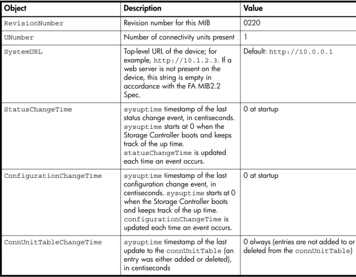
FA MIB 2.2 SNMP behavior . . . 78
External details for connUnitRevsTable . . . 83
External details for connUnitSensorTable . . . 84
External details for connUnitPortTable. . . 85
Configuring SNMP event notification in SMU. . . 85
SNMP management . . . 85
Enterprise trap MIB . . . 85
FA MIB 2.2 and 4.0 Differences. . . 87
B Event code reference . . . 89
C Using FTP to download logs and update firmware. . . 107
Downloading system logs . . . 107
Updating controller module firmware . . . 108
Updating expansion module firmware. . . 109
Updating disk firmware. . . 110
Installing a license file . . . 111
Glossary . . . 113
Figures
1 Relationship between a master volume and its snapshots and snap pool. . . 20 2 Rolling back a master volume . . . 21 3 Creating a volume copy from a master volume or a snapshot . . . 22
Tables
1 Document conventions . . . 11
2 SMU communication status icons . . . 14
3 Settings for default users . . . 16
4 Example applications and RAID levels . . . 23
5 RAID level comparison . . . 23
6 Vdisk expansion by RAID level . . . 24
7 Size representations in base 2 and base 10 . . . 25
8 Decimal (radix) point character by locale . . . 25
9 Storage-space color codes . . . 26
10 FA MIB 2.2 objects, descriptions, and values . . . 78
11 connUnitRevsTable index and description values . . . 83
12 connUnitSensorTable index, name, type, and characteristic values . . . 84
13 connUnitPortTable index and name values . . . 85
14 Event code descriptions and recommended actions . . . 89
15 Disk error conditions and recommended actions . . . 105
About this guide
This guide provides information about managing an 2000 G2 Modular Smart Array storage system by using its web interface, Storage Management Utility (SMU).
Intended audience
This guide is intended for storage system administrators.
Prerequisites
Prerequisites for using this product include knowledge of: • Network administration
• Storage system configuration
• Storage area network (SAN) management and direct attach storage (DAS)
• Fibre Channel, Serial Attached SCSI (SAS), Internet SCSI (iSCSI), and Ethernet protocols
Related documentation
In addition to this guide, please refer to other documents for this product: • HP StorageWorks MSA2000 G2 Installation Instructions
• HP StorageWorks 2000 G2 Modular Smart Array Cable Configuration Guide • HP StorageWorks 2312fc and 2324fc User’s Guide
• HP StorageWorks 2000i G2 Modular Smart Array User’s Guide • HP StorageWorks 2000sa G2 Modular Smart Array User’s Guide • HP StorageWorks 2000 G2 Modular Smart Array CLI Reference Guide
• Online help for HP StorageWorks 2000 G2 Modular Smart Array management interfaces
These and other HP documents can be found on the HP documents web site:http://www.hp.com/support/.
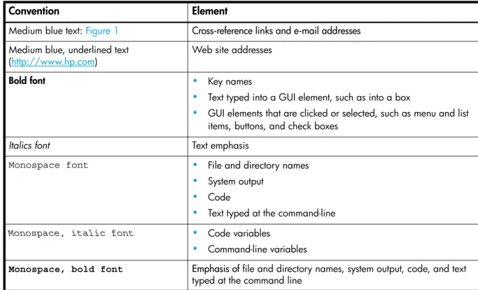
Document conventions and symbols
Table 1 Document conventions
Convention Element
Medium blue text: Figure 1 Cross-reference links and e-mail addresses Medium blue, underlined text
(http://www.hp.com) Web site addresses
Bold font • Key names
• Text typed into a GUI element, such as into a box
• GUI elements that are clicked or selected, such as menu and list items, buttons, and check boxes
Italics font Text emphasis
Monospace font • File and directory names
• System output • Code
• Text typed at the command-line
Monospace, italic font • Code variables
• Command-line variables
Monospace, bold font Emphasis of file and directory names, system output, code, and text typed at the command line
CAUTION: Indicates that failure to follow directions could result in damage to equipment or data.
NOTE: Provides additional information.
TIP: Provides helpful hints and shortcuts.
HP technical support
Telephone numbers for worldwide technical support are listed on the HP support web site:
http://www.hp.com/support/.
Collect the following information before calling:
• Technical support registration number (if applicable) • Product serial numbers
• Product model names and numbers • Applicable error messages
• Operating system type and revision level • Detailed, specific questions
For continuous quality improvement, calls may be recorded or monitored.
Product warranties
For information about HP StorageWorks product warranties, see the warranty information website:
http://www.hp.com/go/storagewarranty
Subscription service
HP strongly recommends that customers sign up online using the Subscriber's choice web site:
http://www.hp.com/go/e-updates.
• Subscribing to this service provides you with e-mail updates on the latest product enhancements, newest versions of drivers, and firmware documentation updates as well as instant access to numerous other product resources.
• After signing up, you can quickly locate your products by selecting Business support and then Storage under Product Category.
HP web sites
For other product information, see the following HP web sites:
• http://www.hp.com
• http://www.hp.com/go/msa
• http://www.hp.com/go/storage
• http://www.hp.com/support/
• http://www.hp.com/service_locator
• http://www.docs.hp.com
Documentation feedback
HP welcomes your feedback.
To make comments and suggestions about product documentation, please send a message to
1
Getting started
Storage Management Utility (SMU) is a web-based application for configuring, monitoring, and managing the storage system.
Each controller module in the storage system contains a web server, which you access when you sign in to SMU. In a dual-controller system, you can access all functions from either controller. If one controller becomes unavailable, you can continue to manage the storage system from the partner controller. SMU is also referred to as the web-browser interface (WBI).
NOTE: It is possible to upgrade an MSA2000 storage system by replacing its controllers with
MSA2000 G2 controllers, which use the version of SMU described in this guide. For upgrade information go to www.hp.com/go/msa2000fc, click Resource Library, and view the PDF “Upgrading the HP
StorageWorks MSA2000fc to the next generation.”
Configuring and provisioning a new storage system
To configure and provision a storage system for the first time:
1. Configure your web browser for SMU and sign in, as described in Browser setup and Signing in below. 2. Set the system date and time, as described in Changing the system date and time on page 36.
3. Use the Configuration Wizard to configure other system settings, as described in Using the Configuration Wizard on page 29.
4. Use the Provisioning Wizard to create a virtual disk (vdisk) containing storage volumes, and optionally to map the volumes to hosts, as described in Using the Provisioning Wizard on page 45.
5. If you mapped volumes to hosts then verify the mappings by mounting the volumes from each host and performing simple read/write tests to the volumes.
6. Verify that controller modules and expansion modules have the latest firmware, as described in Viewing information about the system on page 67 and Updating firmware on page 59.
You can then make additional configuration and provisioning changes and view system status, as described in later chapters of this guide.
Browser setup
• Your browser must be Mozilla Firefox 1.5 or Microsoft Internet Explorer 6, or later. For better performance, use Firefox or Internet Explorer 7 or later.
• To see the help window, you must enable pop-up windows.
• To optimize the display, use a color monitor and set its color quality to the highest setting. • To navigate beyond the Sign In page (with a valid user account):
• Set the browser's local-intranet security option to medium or medium-low.
• Verify that the browser is set to allow cookies at least for the IP addresses of the storage-system network ports.
Signing in
To sign in:
1. In the web browser’s address field, type the IP address of a controller network port and press Enter. The SMU Sign In page is displayed. If the Sign In page does not display, verify that you have entered the correct IP address.
2. On the Sign In page, enter the name and password of a configured user. If you are logging in to SMU for the first time, the Language field displays user setting or English, either of which results in English.
3. Click Sign In. If the system is available, the System Overview page is displayed; otherwise, a message indicates that the system is unavailable.
Tips for signing in and signing out
• Do not include a leading zero in an IP address. For example, enter 10.1.4.6 not 10.1.4.06.
• Each user has a Monitor or Manage access level, as described in About user accounts on page 15. Multiple monitor and manage users can be signed in to each controller simultaneously.
• For each active SMU session an identifier is stored in the browser. Depending on how your browser treats this session identifier, you might be able to run multiple independent sessions simultaneously. Each instance of Internet Explorer can run a separate SMU session; however, all instances of Firefox share the same session.
• If you end a SMU session without clicking the Sign Out link near the top of the SMU window, the session automatically ends when the user's automatic sign-out time expires. If this preference is set to Never, the session ends after 9999 minutes.
Tips for using the main window
• The Configuration View panel displays logical and physical components of the storage system. To perform a task, select the component to act on and then either:
• Right-click to display a context menu and select the task to perform. This is the method that help topics describe.
• Click a task category in the main panel and select the task to perform.
• The System Status panel shows how many events of each severity have occurred in the system. To view event details, click a severity icon.
• Many tables can be sorted by a specific column. To do so, click the column heading to sort low to high; click again to sort high to low.
• Do not use the browser's Back, Forward, Reload, or Refresh buttons. SMU is essentially a single page that is automatically updated to show current data; you do not need to refresh it.
• An asterisk (*) identifies a required setting.
• The icon in the upper right corner of the main window shows the status of communication between SMU, the Management Controller (MC), and the Storage Controller (SC), as described in the following table.
• Below the communication status icon, a timer shows how long the session can be idle until you are automatically signed out. This timer resets after each action you perform. One minute before automatic sign-out you are prompted to continue using SMU. The timer does not appear if the current user's Auto Sign Out preference is set to Never.
• If a SMU session is active on a controller and the controller is power cycled or is forced offline by the partner controller or certain other events occur, the session might hang. SMU might say that it is “Connecting” but stop responding, or the page may become blank with the browser status Done. After the controller comes back online, the session will not restart. To continue using SMU, close and reopen the browser and start a new SMU session.
Table 2 SMU communication status icons
Icon Meaning
SMU can communicate with the Management Controller, which can communicate with the Storage Controller.
SMU cannot communicate with the Management Controller.
SMU can communicate with the Management Controller, which cannot communicate with the Storage Controller.
Tips for using the help window
• In the main panel, click the help icon to display help for the last-selected item, whether it is a component in the Configuration View panel or a subpanel in the main panel.
• In the help window, click the table of contents icon to show or hide the Contents pane.
• A help topic remains displayed until you browse to another topic in the help window, display help for a different item in the main window, or close the help window.
• If you have viewed more than one help topic, you can click the arrow icons to display the previous or next topic.
System concepts
About user accounts
The system provides three default user accounts and allows a maximum of 12 user accounts to be
configured. Any account can be modified or removed except you cannot remove the user you are signed in as.
User accounts have these options:
• User Name. A user name is case sensitive and cannot already exist in the system. A name cannot include a comma, double quote, or backslash.
• Password. A password is case sensitive. A password cannot include a comma, double quote, or backslash. Though optional, passwords are highly recommended to ensure system security.
• Access Level. Select Monitor to let the user view system settings, or Manage to let the user view and change system settings.
• User Type. Select Standard to allow access to standard functions, or Advanced to allow access to all functions except diagnostic functions, or Diagnostic to allow access to all functions.
NOTE: This release has no functions that require Advanced or Diagnostic access; a Standard user can access all functions.
• WBI Access. Allows access to the web-based management interface. • CLI Access. Allows access to the command-line management interface.
• FTP Access. Allows access to the file transfer protocol interface, which provides a way to install firmware updates and download logs.
• Base Preference. The base for entry and display of storage-space sizes. In base 2, sizes are shown as powers of 2, using 1024 as a divisor for each magnitude. In base 10, sizes are shown as powers of 10, using 1000 as a divisor for each magnitude. Operating systems usually show volume size in base 2. Disk drives usually show size in base 10. Memory size is always shown in base 2.
• Precision Preference. The number of decimal places (1–10) for display of storage-space sizes. • Unit Preference. Sets the unit for display of storage-space sizes. The Auto option lets the system
determine the proper unit for a size. Based on the precision setting, if the selected unit is too large to meaningfully display a size, the system uses a smaller unit for that size.
• Temperature Preference. Specifies to use either the Celsius scale or the Fahrenheit scale for temperature values.
• Auto Sign Out. Select the amount of time that the user's session can be idle before the user is automatically signed out: 5, 15, or 30 minutes, or Never (9999 minutes). The default is 30 minutes.
• Locale. The user’s preferred display language, which overrides the system’s default display language. Installed language sets include Chinese-simplified, Chinese-traditional, Dutch, English, French, German, Italian, Japanese, Korean, and Spanish.
NOTE: To secure the storage system, set a new password for each default user.
About vdisks
A vdisk is a “virtual” disk that is composed of one or more disks, and has the combined capacity of those disks. The number of disks that a vdisk can contain is determined by its RAID level. All disks in a vdisk must be the same type (SAS or SATA, small or large form-factor). A maximum of 16 vdisks per controller can exist.
A vdisk can contain different models of disks, and disks with different capacities. For example, a vdisk can include a 500-GB disk and a 750-GB disk. If you mix disks with different capacities, the smallest disk determines the logical capacity of all other disks in the vdisk, regardless of RAID level. For example, if a RAID-0 vdisk contains one 500-GB disk and four 750-GB disks, the capacity of the vdisk is equivalent to approximately five 500-GB disks. To maximize capacity, use disks of similar size. For greatest reliability, use disks of the same size and rotational speed.
Each disk has metadata that identifies whether the disk is a member of a vdisk, and other members of that vdisk. This enables disks to be moved to different slots in a system; an entire vdisk to be moved to a different system; and a vdisk to be quarantined if a disk is detected missing.
In a single-controller system, all vdisks are owned by that controller. In a dual-controller system, when a vdisk is created the system automatically assigns the owner to balance the number of vdisks each controller owns; or, you can select the owner. Typically it does not matter which controller owns a vdisk.
In a dual-controller system, when a controller fails, the partner controller assumes temporary ownership of the failed controller's vdisks and resources. If the system uses a fault-tolerant cabling configuration, both controllers' LUNs become accessible through the partner.
When you create a vdisk you can also create volumes within it. A volume is a logical subdivision of a vdisk, and can be mapped to controller host ports for access by hosts. The storage system presents only volumes, not vdisks, to hosts.
You can create vdisks with or without volumes by using the Provisioning Wizard, or you can create vdisks manually.
About spares
A controller automatically reconstructs a redundant (fault-tolerant) vdisk (RAID 1, 3, 5, 6, 10, 50) when one or more of its disks fails and a properly sized spare disk is available.
There are three types of spares:
• Dedicated spare. Reserved for use by a specific vdisk to replace a failed disk. Most secure way to provide spares for vdisks but expensive to reserve a spare for each vdisk.
• Global spare. Reserved for use by any redundant vdisk to replace a failed disk.
• Dynamic spare. A properly sized available disk that is automatically assigned to replace a failed disk in a redundant vdisk.
Table 3 Settings for default users
Name Password Level Type WBI CLI FTP Base Prec. Units Temp. Auto Sign Out
Locale
monitor !monitor Monitor Standard Yes Yes No 10 1 Auto Celsius 30
Min. English manage !manage Manage Yes Yes Yes
When a disk fails, the system looks for a dedicated spare first. If it does not find a properly sized dedicated spare, it looks for a global spare. If it does not find a properly sized global spare and the dynamic spares option is enabled, it takes any properly sized available disk. If no properly sized spares are available, reconstruction cannot start.
About volumes
A volume is a logical subdivision of a vdisk, and can be mapped to controller host ports for access by hosts. This type of volume provides the storage for a file system partition you create with your operating system or third-party tools. The storage system presents only volumes, not vdisks, to hosts. A vdisk can have a maximum of 128 volumes.
You can create a vdisk that has one volume or multiple volumes.
• Single-volume vdisks work well in environments that need one large, fault-tolerant storage space for data on one host. A large database accessed by users on a single host that is used only for that application is an example.
• Multiple-volume vdisks work well when you have very large disks and you want to make the most efficient use of disk space for fault tolerance (parity and spares). For example, you could create one very large RAID-5 vdisk and dedicate one spare to the vdisk. This minimizes the amount of disk space allocated to parity and spares compared to the space required if you created five or six smaller RAID-5 vdisks. However, I/O to multiple volumes in the same vdisk can slow system performance.
When you create volumes you can specify their sizes. If the total size of a vdisk's volumes equals the size of the vdisk, you will not have any free space. Without free space, you cannot add or expand volumes. If you need to add or expand a volume in a vdisk without free space, you can delete a volume to create free space. Or, you can expand the vdisk and then either add a volume or expand a volume to use the new free space.
You can use a volume's default name or change it to identify the volume's purpose. For example, a volume used to store payroll information can be named Payroll.
You can create vdisks with volumes by using the Provisioning Wizard, or you can create volumes manually.
About hosts
A host identifies an external port that the storage system is attached to. The external port may be a port in an I/O adapter in a server, or a port in a network switch. Examples of I/O adapters are FC HBAs. The controllers automatically add hosts that have sent an inquiry command or a report luns command to the storage system. Hosts typically do this when they boot up or rescan for devices. When the command from the host occurs, the system saves the host ID. The ID for an FC or SAS host is its WWPN. The ID for an iSCSI host is typically, but not limited to, its IQN.
You must assign a name to an automatically added host to have the system retain it after a restart. Naming hosts also makes them easy to recognize for volume mapping. A maximum of 64 names can be assigned. The Configuration View panel lists hosts by name, or if they are unnamed, by ID.
iSCSI host security
The storage system can be protected from unauthorized access via iSCSI by enabling Challenge Handshake Authentication Protocol (CHAP). CHAP authentication occurs during an attempt by a host to login to the system. This authentication requires an identifier for the host and a shared secret between the host and the system. Optionally, the storage system can also be required to authenticate itself to the host; this is called mutual CHAP.
The host node identifier is typically, but not limited to, its IQN. A secret can have 12–16 characters. Steps involved in enabling CHAP include:
• Decide on host node names and secrets.
• Define CHAP entries in the storage system. If the node name is a host name, then it may be useful to display the hosts that are known to the system.
• Enable CHAP on the storage system. Note that this applies to all iSCSI hosts, in order to avoid security exposures.
• Define CHAP secret in the host iSCSI initiator.
• Request host login to the storage system. The host should be displayable by the system, as well as the ports through which connections were made.
If it becomes necessary to add more hosts after CHAP is enabled, additional CHAP node names and secrets can be added. If a host attempts to login to the storage system, it will become visible to the system, even if the full login is not successful due to incompatible CHAP definitions. This information may be useful in configuring CHAP entries for new hosts. This information becomes visible when an iSCSI discovery session is established, because the storage system does not require discovery sessions to be authenticated.
About volume mapping
Each volume has default host-access settings that are set when the volume is created; these settings are called the default mapping. The default mapping applies to any host that has not been explicitly mapped using different settings. Explicit mappings for a volume override its default mapping.
Default mapping enables all attached hosts to see a volume using a specified LUN and access permissions set by the administrator. This means that when the volume is first created, all connected hosts can
immediately access the volume using the advertised default mapping settings. This behavior is expected by some operating systems, such as Microsoft Windows, which can immediately discover the volume. The advantage of a default mapping is that all connected hosts can discover the volume with no additional work by the administrator. The disadvantage is that all connected hosts can discover the volume with no restrictions. Therefore, this process is not recommended for specialized volumes such as payroll databases. You can change a volume's default mapping, and create, modify, or delete explicit mappings. A mapping can specify read-write, read-only, or no access through one or more controller host ports to a volume. When a mapping specifies no access, the volume is masked. You can apply access privileges to one or more of the host ports on either controller. To maximize performance, it is recommended to map a volume to at least one host port on the controller that owns it. To sustain I/O in the event of controller failure, it is recommended to map to at least one host port on each controller.
Continuing the example of the payroll volume, it could be mapped with read-write access for the Human Resources host and be masked for all other hosts. An engineering volume could be mapped with read-write access for the Engineering host and read-only access for other departments’ hosts.
A LUN identifies a mapped volume to a host. Both controllers share a set of LUNs, and any unused LUN can be assigned to a mapping; however, each LUN can only be used once per volume as its default LUN. For example, if LUN 5 is the default for Volume1, no other volume in the storage system can use LUN 5 as its default LUN. For explicit mappings, the rules differ: LUNs used in default mappings can be reused in explicit mappings for other volumes and other hosts.
TIP: When an explicit mapping is deleted, the volume’s default mapping takes effect. Therefore, it is recommended to use the same LUN for explicit mappings as for the default mapping.
Volume mapping settings are stored in disk metadata. If enough of the disks used by a volume are moved into a different enclosure, the volume's vdisk can be reconstructed and the mapping data is preserved.
About volume cache options
You can set options that optimize reads and writes performed for each volume.
Using write-back or write-through caching
NOTE: Only disable write-back caching if you fully understand how the host operating system, application, and adapter move data. If used incorrectly, you might hinder system performance.
You can change a volume's write-back cache setting. Write-back is a cache-writing strategy in which the controller receives the data to be written to disks, stores it in the memory buffer, and immediately sends the host operating system a signal that the write operation is complete, without waiting until the data is actually written to the disk. Write-back cache mirrors all of the data from one controller module cache to the other. Write-back cache improves the performance of write operations and the throughput of the controller. When write-back cache is disabled, write-through becomes the cache-writing strategy. Using write-through cache, the controller writes the data to the disks before signaling the host operating system that the process is complete. Write-through cache has lower write operation and throughput performance than write-back, but it is the safer strategy, with minimum risk of data loss on power failure. However, write-through cache does not mirror the write data because the data is written to the disk before posting command completion and mirroring is not required. You can set conditions that cause the controller to change from write-back caching to write-through caching.
In both caching strategies, active-active failover of the controllers is enabled.
You can enable and disable the write-back cache for each volume. By default, volume write-back cache is enabled. Because controller cache is backed by super-capacitor technology, if the system loses power, data is not lost. For most applications, this is the correct setting. But because back-end bandwidth is used to mirror cache and because this mirroring uses back-end bandwidth, if you are writing large chunks of sequential data (as would be done in video editing, telemetry acquisition, or data logging), write-through cache has much better performance. Therefore, you might want to experiment with disabling the write-back cache. You might see large performance gains (as much as 70 percent) if you are writing data under the following circumstances:
• Sequential writes
• Large I/Os in relation to the chunk size • Deep queue depth
If you are doing random access to this volume, leave the write-back cache enabled.
Optimizing read-ahead caching
CAUTION: Only change read-ahead cache settings if you fully understand how the host operating system, application, and adapter move data so that you can adjust the settings accordingly.
You can optimize a volume for sequential reads or streaming data by changing its read-ahead cache settings. Read ahead is triggered by two back-to-back accesses to consecutive LBA ranges, whether forward (increasing LBAs) or reverse (decreasing LBAs).
You can change the amount of data read in advance after two back-to-back reads are made. Increasing the read-ahead cache size can greatly improve performance for multiple sequential read streams; however, increasing read-ahead size will likely decrease random read performance.
• The Default option works well for most applications: it sets one chunk for the first access in a sequential read and one stripe for all subsequent accesses. The size of the chunk is based on the chunk size used when you created the vdisk (the default is 64 KB). Non-RAID and RAID-1 vdisks are considered to have a stripe size of 64 KB.
• The Maximum option lets the controller dynamically calculate the maximum read-ahead cache size for the volume. For example, if a single volume exists, this setting enables the controller to use nearly half the memory for read-ahead cache. Only use Maximum when disk latencies must be absorbed by cache.
• The Disabled option turns off read-ahead cache. This is useful if the host is triggering read ahead for what are random accesses. This can happen if the host breaks up the random I/O into two smaller reads, triggering read ahead.
You can also change the optimization mode. The standard read-ahead caching mode works well for typical applications where accesses are a combination of sequential and random; this method is the default. For an application that is strictly sequential and requires extremely low latency, you can use Super Sequential mode. This mode makes more room for read-ahead data by allowing the controller to discard cache contents that have been accessed by the host.
About the Snapshot feature
Snapshot is a licensed feature that provides data protection by enabling you to create and save snapshots of a volume. Each snapshot preserves the source volume's data state at the point in time when the snapshot was created. Snapshots can be created manually or by using the task scheduler.
When the first snapshot is taken of a standard volume, the system automatically converts the volume into a
master volume and reserves additional space for snapshot data. This reserved space, called a snap pool, stores pointers to the source volume's data. Each master volume has its own snap pool. The system treats a snapshot like any other volume; the snapshot can be mapped to hosts with read-only access, read-write access, or no access, depending on the snapshot's purpose. Any additional unique data written to a snapshot is also stored in the snap pool.
The following figure shows how the data state of a master volume is preserved in the snap pool by two snapshots taken at different points in time. The dotted line used for the snapshot borders indicates that snapshots are logical volumes, not physical volumes as are master volumes and snap pools.
Figure 1 Relationship between a master volume and its snapshots and snap pool
The snapshot feature uses the single copy-on-write method to capture only data that has changed. That is, if a block is to be overwritten on the master volume, and a snapshot depends on the existing data in the block being overwritten, the data is copied from the master volume to the snap pool before the data is changed. All snapshots that depend on the older data are able to access it from the same location in the snap pool; this reduces the impact of snapshots when writing to a master volume. In addition, only a single copy-on-write operation is performed on the master volume.
The storage system allows a maximum number of snapshots to be retained, as determined by an installed license. For example, if your license allows four snapshots, when the fifth snapshot is taken an error message informs you that you have reached the maximum number of snapshots allowed on your system. Before you can create a new snapshot you must either delete an existing snapshot, or purchase and install a license that increases the maximum number of snapshots.
MasterVolume-1 Snap Pool-1
Snapshot-1
Snapshot-2 (Monday)
The snapshot service has two features for reverting data back to original data:
• Deleting only modified data on a snapshot. For snapshots that have been made accessible as read-write, you can delete just the modified (write) data that was written directly to a snapshot. When the modified data is deleted, the snapshot data reverts to the original data that was snapped. This feature is useful for testing an application, for example. You might want to test some code, which writes data to the snapshot. Rather than having to take another snapshot, you can just delete any write data and start again.
• Rolling back the data in a source volume. The rollback feature enables you to revert the data in a source volume to the data that existed when a specified snapshot was created (preserved data). Alternatively, the rollback can include data that has been modified (write data) on the snapshot since the snapshot was taken. For example, you might want to take a snapshot, mount that snapshot for read/write, and then install new software on that snapshot for test purposes. If the software installation is successful, you can rollback the master volume to the contents of the modified snapshot (preserved data plus the write data).
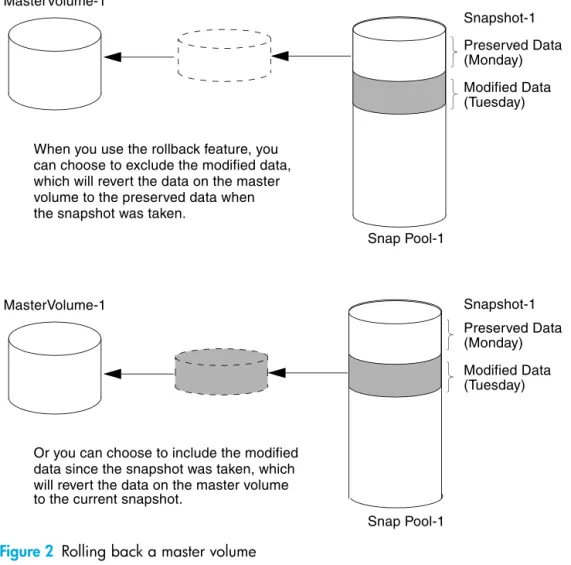
The following figure shows the difference between rolling back the master volume to the data that existed when a specified snapshot was created (preserved), and rolling back preserved and modified data.
Figure 2 Rolling back a master volume
About the Volume Copy feature
Volume Copy is a licensed feature that enables you to copy a volume or a snapshot to a new standard volume.
While a snapshot is a point-in-time logical copy of a volume, the volume copy service creates a complete “physical” copy of a volume within a storage system. It is an exact copy of a source volume as it existed at the time the volume copy operation was initiated, consumes the same amount of space as the source volume, and is independent from an I/O perspective. Volume independence is a key distinction of a volume copy (versus a snapshot, which is a “virtual” copy and dependent on the source volume).
MasterVolume-1
Snap Pool-1
MasterVolume-1
Snap Pool-1
Snapshot-1
(Monday) Preserved Data
Modified Data (Tuesday)
Snapshot-1
Modified Data (Tuesday) When you use the rollback feature, you
can choose to exclude the modified data, which will revert the data on the master volume to the preserved data when the snapshot was taken.
(Monday) Preserved Data
Or you can choose to include the modified data since the snapshot was taken, which will revert the data on the master volume to the current snapshot.
Benefits include:
• Additional data protection. An independent copy of a volume (versus logical copy through snapshot) provides additional data protection against a complete master volume failure. If the source master volume fails, the volume copy can be used to restore the volume to the point in time the volume copy was taken.
• Non-disruptive use of production data. With an independent copy of the volume, resource contention and the potential performance impact on production volumes is mitigated. Data blocks between the source and the copied volumes are independent (versus shared with snapshot) so that I/O is to each set of blocks respectively; application I/O transactions are not competing with each other when accessing the same data blocks.
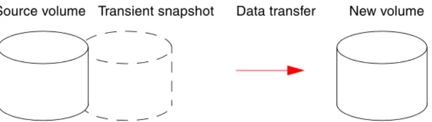
The following figure illustrates how volume copies are created.
Figure 3 Creating a volume copy from a master volume or a snapshot Guidelines to keep in mind when performing a volume copy include:
• The destination vdisk must be owned by the same controller as the source volume.
• The destination vdisk must have free space that is at least as large as the mount of space allocated to the original volume. A new volume will be created using this free space for the volume copy.
• The destination vdisk does not need to have the same attributes (such as disk type, RAID level) as the volume being copied.
• Once the copy is complete, the new volume will no longer have any ties to the original.
• Volume Copy makes a copy from a snapshot of the source volume; therefore, the snap pool for the source volume must have sufficient space to store snapshot data when performing this copy. Source volume Transient snapshot Data transfer New volume
1. Volume copy request is made with a standard volume or a master volume as the source. 3. A new volume is created for the volume copy, and a hidden, transient snapshot is created. 4. Data is transferred from the transient snapshot to the new volume.
5. On completion, the transient volume is deleted and the new volume is a completely independent copy of the master volume, representing the data that was present when the volume copy was started.
Creating a volume copy from a standard or master volume
Master volume Snapshot(s) Data transfer New volume
1. A master volume exists with one or more snapshots associated with it. Snapshots can be in their original Creating a volume copy from a snapshot
state or they can be modified.
2. You can select any snapshot to copy, and you can specify that the modified or unmodified data be copied. 3. On completion, the new volume is a completely independent copy of the snapshot. The snapshot remains,
though you can choose to delete it.
About the VDS and VSS hardware providers
Virtual Disk Service (VDS) enables host-based applications to manage vdisks and volumes. Volume Shadow Copy Service (VSS) enables host-based applications to manage snapshots. For more information, see the VDS and VSS hardware provider documentation for your product.
About RAID levels
The RAID controllers enable you to set up and manage vdisks, whose storage may be spread across multiple disks. This is accomplished through firmware resident in the RAID controller. RAID refers to vdisks in which part of the storage capacity may be used to store redundant data. The redundant data enables the system to reconstruct data if a disk in the vdisk fails.
Hosts see each partition of a vdisk, known as a volume, as a single disk. A volume is actually a portion of the storage space on disks behind a RAID controller. The RAID controller firmware makes each volume appear as one very large disk. Depending on the RAID level used for a vdisk, the disk presented to hosts has advantages in fault-tolerance, cost, performance, or a combination of these.
NOTE: Choosing the right RAID level for your application improves performance. The following tables:
• Provide examples of appropriate RAID levels for different applications • Compare the features of different RAID levels
• Describe the expansion capability for different RAID levels Table 4 Example applications and RAID levels
Application RAID level
Testing multiple operating systems or software development (where redundancy is not an issue) NRAID Fast temporary storage or scratch disks for graphics, page layout, and image rendering 0
Workgroup servers 1 or 10
Video editing and production 3
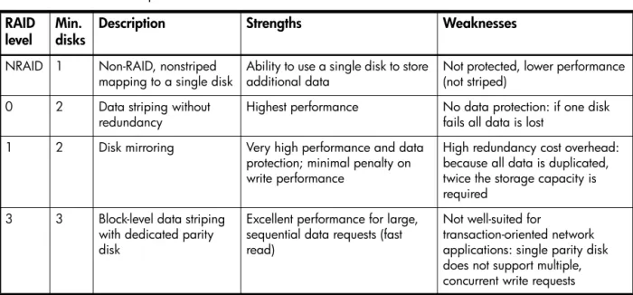
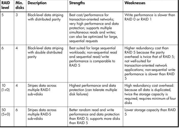
Network operating system, databases, high availability applications, workgroup servers 5 Very large databases, web server, video on demand 50 Mission-critical environments that demand high availability and use large sequential workloads 6 Table 5 RAID level comparison
RAID
level Min. disks Description Strengths Weaknesses
NRAID 1 Non-RAID, nonstriped
mapping to a single disk Ability to use a single disk to store additional data Not protected, lower performance (not striped) 0 2 Data striping without
redundancy Highest performance No data protection: if one disk fails all data is lost 1 2 Disk mirroring Very high performance and data
protection; minimal penalty on write performance
High redundancy cost overhead: because all data is duplicated, twice the storage capacity is required
3 3 Block-level data striping with dedicated parity disk
Excellent performance for large, sequential data requests (fast read)
Not well-suited for
transaction-oriented network applications: single parity disk does not support multiple, concurrent write requests
5 3 Block-level data striping
with distributed parity Best cost/performance for transaction-oriented networks; very high performance and data protection; supports multiple simultaneous reads and writes; can also be optimized for large, sequential requests
Write performance is slower than RAID 0 or RAID 1
6 4 Block-level data striping with double distributed parity
Best suited for large sequential workloads; non-sequential read and sequential read/write performance is comparable to RAID 5
Higher redundancy cost than RAID 5 because the parity overhead is twice that of RAID 5; not well-suited for
transaction-oriented network applications; non-sequential write performance is slower than RAID 5
10
(1+0) 4 Stripes data across multiple RAID-1 sub-vdisks
Highest performance and data protection (can tolerate multiple disk failures)
High redundancy cost overhead: because all data is duplicated, twice the storage capacity is required; requires minimum of four disks
50
(5+0) 6 Stripes data across multiple RAID-5 sub-vdisks
Better random read and write performance and data protection than RAID 5; supports more disks than RAID 5
Lower storage capacity than RAID 5
Table 6 Vdisk expansion by RAID level
RAID level Expansion capability Maximum disks
NRAID Cannot expand. 1
0, 3, 5, 6 You can add 1–4 disks at a time. 16
1 Cannot expand. 2
10 You can add 2 or 4 disks at a time. 16
50 You can add one sub-vdisk at a time. The added sub-vdisk must contain the same number of disks as each of the existing sub-vdisks. 32 Table 5 RAID level comparison (continued)
RAID
About size representations
In SMU panels, parameters such as names of users and volumes have a maximum length in bytes. ASCII characters are 1 byte; most Latin (Western European) characters with diacritics are 2 bytes; most Asian characters are 3 bytes.
Operating systems usually show volume size in base 2. Disk drives usually show size in base 10. Memory size is always shown in base 2. In SMU, the base for entry and display of storage-space sizes can be set per user or per session. When entering storage-spaces sizes only, either base-2 or base-10 units can be specified.
The locale setting determines the character used for the decimal (radix) point, as shown below.
About the system date and time
You can change the storage system's date and time, which are displayed in the System Status panel. It is important to set the date and time so that entries in system logs and event-notification email messages have correct time stamps.
You can set the date and time manually or configure the system to use Network Time Protocol (NTP) to obtain them from a network-attached server. When NTP is enabled, and if an NTP server is available, the system time and date can be obtained from the NTP server. This allows multiple storage devices, hosts, log files, and so forth to be synchronized. If NTP is enabled but no NTP server is present, the date and time are maintained as if NTP was not enabled.
NTP server time is provided in Universal Time (UT), which provides several options:
• If you want to synchronize the times and logs between storage devices installed in multiple time zones, set all the storage devices to use UT.
• If you want to use the local time for a storage device, set its time zone offset.
• If a time server can provide local time rather than UT, configure the storage devices to use that time server, with no further time adjustment.
Whether NTP is enabled or disabled, the storage system does not automatically make time adjustments, such as for U.S. daylight savings time. You must make such adjustments manually.
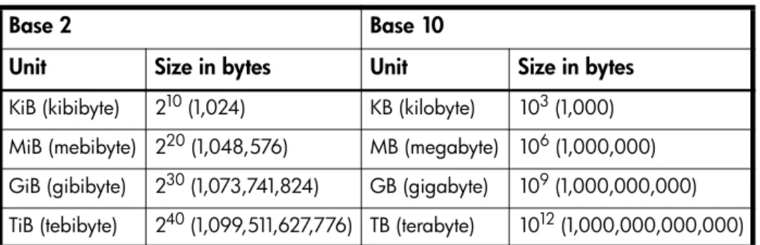
Table 7 Size representations in base 2 and base 10
Base 2 Base 10
Unit Size in bytes Unit Size in bytes
KiB (kibibyte) 210 (1,024) KB (kilobyte) 103 (1,000) MiB (mebibyte) 220 (1,048,576) MB (megabyte) 106 (1,000,000) GiB (gibibyte) 230 (1,073,741,824) GB (gigabyte) 109 (1,000,000,000) TiB (tebibyte) 240 (1,099,511,627,776) TB (terabyte) 1012 (1,000,000,000,000) Table 8 Decimal (radix) point character by locale
Language Character Examples
English, Chinese, Japanese, Korean Period (.) 146.81 GB 3.0 Gb/s Dutch, French, German, Italian, Spanish Comma (,) 146,81 GB
About storage-space color codes
SMU panels use the following color codes to identify how storage space is used.
About vdisk reconstruction
If one or more disks fail in a redundant vdisk (RAID 1, 3, 5, 6, 10, or 50) and properly sized spares are available, the storage system automatically uses the spares to reconstruct the vdisk. Vdisk reconstruction does not require I/O to be stopped, so the vdisk can continue to be used while the Reconstruct utility runs. A properly sized spare is one whose capacity is equal to or greater than the smallest disk in the vdisk. If no properly sized spares are available, reconstruction does not start automatically. To start reconstruction manually, replace each failed disk and then do one of the following:
• Add each new disk as either a dedicated spare or a global spare. Remember that a global spare might be taken by a different critical vdisk than the one you intended.
• Enable the Dynamic Spare Capability option to use the new disks without designating them as spares. Reconstructing a RAID-6 vdisk to a fault-tolerant state requires two properly sized spares to be available. • If two disks fail and only one properly sized spare is available, an event indicates that reconstruction is
about to start. The Reconstruct utility starts to run, using the spare, but its progress remains at 0% until a second properly sized spare is available.
• If a disk fails during online initialization, the initialization fails. In order to generate the two sets of parity that RAID 6 requires, the controller fails a second disk in the vdisk, which changes the vdisk status to Critical, and then assigns that disk as a spare for the vdisk. The Reconstruct utility starts to run, using the spare, but its progress remains at 0% until a second properly sized spare is available. The second available spare can be an existing global spare, another existing spare for the vdisk, or a replacement disk that you designate as a spare or that is automatically taken when dynamic sparing is enabled.
During reconstruction, you can continue to use the vdisk. When a global spare replaces a disk in a vdisk, the global spare’s icon in the enclosure view changes to match the other disks in that vdisk.
NOTE: Reconstruction can take hours or days to complete, depending on the vdisk RAID level and size, disk speed, utility priority, and other processes running on the storage system. You can stop reconstruction only by deleting the vdisk.
Table 9 Storage-space color codes
Area Color Meaning
Overview panels Total space
Available/free space Used space
Reserved space, used for parity and snap pools, for example Vdisk panels Space used by spares
About data protection in a single-controller storage system
A 2000 G2 Modular Smart Array storage system can be purchased or operated with a single controller. Because single-controller mode is not a redundant configuration, this section presents some considerations concerning data protection.
A volume’s default caching mode is write back, as opposed to write through. In write-back mode, data is held in controller cache until it is written to disk. In write-through mode, data is written directly to disk. If the controller fails while in write-back mode, unwritten cache data likely exists. The same is true if the controller enclosure or the target volume's enclosure is powered off without a proper shut down. Data remains in the controller's cache and associated volumes will be missing that data. This can result in data loss or in some cases volume loss; for example, if using snapshot functionality a snap pool might become inaccessible and the master volume could go offline.
If the controller can be brought back online long enough to perform a proper shut down, the controller should be able to write its cache to disk without causing data loss.
If the controller cannot be brought back online long enough to write its cache data to disk, you can move its CompactFlash cache card to a replacement controller. This enables the cache data to be available when the new controller comes online. The CompactFlash card is externally accessible from the back of the controller.
To avoid the possibility of data loss in case the controller fails you can change a volume's caching mode to write through. While this will cause significant performance degradation, this configuration guards against data loss. While write-back mode is much faster, this mode is not guaranteed against data loss in the case of a controller failure. If data protection is more important, use write-through caching; if performance is more important, use write-back caching.
For details about caching modes see About volume cache options on page 19. To change a volume’s caching mode, see Changing a volume's cache settings on page 44.
2
Configuring the system
Using the Configuration Wizard
The Configuration Wizard helps you initially configure the system or change system configuration settings. The wizard has several steps, which are highlighted at the bottom of the panel as you complete them. The last step prompts you to confirm changes before applying them. If you cancel the wizard, no changes are made.
Step 1: Starting the wizard
1. In the Configuration View panel, right-click the system and select either Configuration > Configuration Wizard or Wizards > Configuration Wizard. The wizard panel appears.
2. Click Next to continue.
Step 2: Change default passwords
The system provides the default users manage and monitor. To secure the storage system, set a new password for each default user. A password is case sensitive. A password cannot include a comma, double quote, or backslash. Though optional, passwords are highly recommended to ensure system security.
Click Next to continue.
Step 3: Configuring network ports
You can configure addressing parameters for each controller's network port. You can set static IP values or use DHCP.
In DHCP mode, network port IP address, subnet mask, and gateway values are obtained from a DHCP server if one is available. If a DHCP server is unavailable, current addressing is unchanged. You must have some means of determining what addresses have been assigned, such as the list of bindings on the DHCP server.
NOTE: Changing IP settings can cause management hosts to lose access to the storage system.
To use DHCP to obtain IP values for network ports
1. Set IP address source to DHCP. 2. Click Next to continue.
To set static IP values for network ports
1. Determine the IP address, subnet mask, and gateway values to use for each controller. 2. Set IP address source to manual.
3. Set the values for each controller. You must set a unique IP address for each network port. 4. Click Next to continue.
Step 4: Enabling system-management services
You can enable or disable management-interface services to limit the ways in which users and host-based management applications can access the storage system. Network management interfaces operate out-of-band and do not affect host I/O to the system. The network options are:
• Web Browser Interface (WBI). The primary interface for managing the system. You can enable use of HTTP, of HTTPS for increased security, or both.
• Command Line Interface (CLI). An advanced user interface for managing the system. You can enable use of Telnet, of SSH (secure shell) for increased security, or both.
• Storage Management Initiative Spec. (SMIS). Used for remote management of the system through your network.
• File Transfer Protocol (FTP). A secondary interface for installing firmware updates, downloading logs, and installing a license.
• Simple Network Management Protocol (SNMP). Used for remote monitoring of the system through your network.
• Service Interface. Used for technical support only. • Service Debug. Used for technical support only.
In-band management interfaces operate through the data path and can slightly reduce I/O performance. The in-band options are:
• In-band CAPI Capability. Used for in-band management of the system from custom, host-based management applications written using the Configuration Application Programming Interface (CAPI). • In-band SES Capability. Used for in-band monitoring of system status based on SCSI Enclosure Services
(SES) data.
If a service is disabled, it continues to run but cannot be accessed. To allow users to access WBI, CLI, or FTP, see About user accounts on page 15.
To change management interface settings
1. Enable the options that you want to use to manage the storage system, and disable the others. 2. Click Next to continue.
Step 5: Setting system information
Enter a name, contact person, location, and description for the system. The system name is shown in the browser title bar or tab. All four values are recorded in system debug logs for reference by service personnel. Click Next to continue.
Step 6: Configuring event notification
Configure up to four email addresses and three SNMP trap hosts to receive notifications of system events. 1. In the Email Configuration section, set the options:
• Notification Level. Select the minimum severity for which the system should send notifications: Critical (only); Warning (and Critical); Informational (all). The default is none, which disables email notification.
• SMTP Server address. The IP address of the SMTP mail server to use for the email messages. If the mail server is not on the local network, make sure that the gateway IP address was set in the network configuration step.
• Sender Name. The sender name that, with the domain name, forms the “from” address for remote notification. Because this name is used as part of an email address, do not include spaces. If no sender name is set, a default name is created.
• Sender Domain. The domain name that, with the sender name, forms the “from” address for remote notification. Because this name is used as part of an email address, do not include spaces. If no domain name is set here, the default domain value is used. If the domain name is not valid, some email servers will not process the mail.
• Email Address fields. Up to four email addresses that the system should send notifications to. Email addresses must use the format user-name@domain-name.
2. In the SNMP Configuration section, set the options:
• Notification Level. Select the minimum severity for which the system should send notifications: Critical (only); Warning (and Critical); Informational (all). The default is none, which disables SNMP notification.
• Read Community. The SNMP read password for your network. The value is case sensitive. The default is public.
• Write Community. The SNMP write password for your network. The value is case sensitive. The default is private.
• Trap Host Address fields. IP addresses of up to three host systems that are configured to receive SNMP traps.
3. Click Next to continue.
Step 7: Configuring host ports
In order for hosts to properly access the system, you must configure the system's host-interface options. For FC ports you can set these options:
• Speed can be set to auto, which auto-negotiates the proper link speed with the host, or to 2Gb (Gbit per second) or 4Gb. A speed mismatch with a host prevents that host from accessing the storage system.
• Connection mode can be set to loop or point-to-point. Loop protocol can be used in a physical loop or in a direct physical connection between two devices. Point-to-point protocol can only be used on a direct physical connection between exactly two devices.
• Loop IDs can be set, per controller, to use soft or hard target addressing:
• Soft target addressing (the default) enables a LIP to determine the loop ID. Use this setting if the loop ID is permitted to change after a LIP or power cycle.
• Hard target addressing requests a specific loop ID that should remain after a LIP or power cycle. If the port cannot acquire the specified ID, it is assigned a soft target address. Use this option if you want ports to have specific addresses, if your system checks addresses in reverse order (lowest address first), or if an application requires that specific IDs be assigned to recognize the controller. For iSCSI ports you can set these options:
• IP Address. The port IP address in IPv4 format. • Netmask. The port netmask address in IPv4 format. • Gateway. The port gateway address in IPv4 format.
• Authentication (CHAP). Enables or disables use of Challenge Handshake Authentication Protocol. Disabled by default.
• Jumbo Frames. Enables or disables support for jumbo frames. A normal frame can contain 1500 bytes whereas a jumbo frame can contain a maximum of 9000 bytes for larger data transfers. Disabled by default.
NOTE: Use of jumbo frames can succeed only if jumbo-frame support is enabled on all network components in the data path.
• Link Speed. Sets the link speed to auto, which allows the system to negotiate the proper speed, or forces it to 1 Gbit/sec (1g). The default is auto.
• iSNS. Enables or disables registration with a specified Internet Storage Name Service server, which provides name-to-IP-address mapping. Disabled by default.
• iSNS Address. Specifies the IP address of an iSNS server. The default address is all zeroes. • Alternate iSNS Address. Specifies the IP address of an alternate iSNS server, which can be on a
different subnet. The default address is all zeroes.
For SAS ports there are no host-interface options. Click Next to continue.
To change FC host-interface settings
1. For controller host ports that are attached to hosts:
• Set the speed to the proper value to communicate with the host. • Set the connection mode to loop or point-to-point.
2. For each controller, set the loop ID to use soft or hard target addressing. To use soft target addressing, select Soft?. To use hard target addressing, clear Soft? and enter an address in the range 0–125. You cannot set the same hard target address for both controllers. An asterisk indicates that the value shown will be changed.
To change iSCSI host-interface settings
1. For each iSCSI port, set the IP address, netmask, and gateway.
2. For all iSCSI ports, set the authentication, jumbo frames, link speed, and iSNS options. 3. Click Next to continue.
Step 8: Confirming configuration changes
Confirm that the values listed in the wizard panel are correct.
• If they are not correct, click Previous to return to previous steps and make necessary changes. • If they are correct, click Finish to apply the setting changes and finish the wizard.
NOTE: If you changed a controller’s FC loop ID setting, you must restart the controller to make the change take effect.
Installing a license
A license is required to expand Snapshot limits and to use Volume Copy. The license is specific to a controller enclosure serial number and firmware version.
If a permanent license is not installed and you want to try the Snapshot and Volume Copy features before buying a permanent license, you can create a temporary license one time. A temporary license will expire 60 days from the time it is created. After creating a temporary license, each time you sign in to SMU, a message specifies the time remaining in the trial period. If you do not install a permanent license before the temporary license expires, you cannot create new snapshots or volume copies; however, you can continue to use existing snapshots and volume copies.
After a temporary license is created or a permanent license is installed, the option to create a temporary license is no longer displayed.
To view information about system licenses
In the Configuration View panel, right-click the system and select Tools > Install License. The System Licenses table shows the following information about licensed features: • License Key. The license key number or “not installed” if no license is installed. • Licensed Snapshots. The number of snapshots that the installed license provides. • Maximum Licensable Snapshots. The number of snapshots that the product supports. • Volume Copy. Shows whether volume copy functions are enabled or disabled. • VDS. Shows that the VDS (Virtual Disk Service) Hardware Provider is enabled.
• VSS. Shows that the VSS (Virtual Shadow Copy Service) Hardware Provider is enabled.
• License Duration. Shows the number of days remaining in the trial period if a temporary license is installed.
The panel also shows the licensing serial number (controller enclosure serial number) and licensing version number (controller firmware version), for which a license file must be generated in order to successfully install.
To create a temporary license
1. In the Configuration View panel, right-click the system and select Tools > Install License. If the option to create a temporary license is available, the End User License Agreement appears in the lower portion of the license panel.
2. Read the license agreement.
3. If you accept the terms of the license agreement, select the checkbox. A confirmation dialog appears. 4. Click Yes to start the trial period. The time remaining in the trial period is shown in the panel's License