DOC022.53.80451
Pocket Colorimeter II
User Manual
04/2014, Edition 1
Table of Contents
Section 1 Specifications... 3
Section 2 General information... 5
2.1 Safety information ... 5
2.1.1 Use of hazard information ... 5
2.1.2 Precautionary labels ... 6
2.1.3 Certification ... 6
2.2 Product overview ... 7
Section 3 Startup... 9
3.1 Install the batteries ... 9
3.2 Install the cap cord ... 10
Section 4 User interface and navigation... 11
4.1 Keypad description ... 11
4.2 Display description ... 11
Section 5 Operation... 13
5.1 Configure the instrument ... 13
5.2 Run a test ...13
5.3 Show the recorded measurements ... 16
5.4 Standard calibration adjust ... 17
5.4.1 Adjust the factory calibration with a standard ... 17
5.4.2 Set the standard calibration adjust to off ... 18
5.5 User-entered calibration ... 18
5.5.1 Channel restrictions ... 18
5.5.2 Enter a calibration curve with standards ... 19
5.5.3 Enter a calibration curve with the keypad ... 20
5.5.4 Remove a calibration point ... 21
5.5.5 Set to the factory default calibration ... 22
Section 1 Specifications
Specifications are subject to change without notice.
Specification Details
Dimensions (W x D x H) 6.1 x 3.2 x 15.2 cm (2.4 x 1.25 x 6 in.)
Enclosure IP67, waterproof at 1 m (3.3 ft) for 30 minutes (battery compartment not included). Keep out of direct sunlight.
Light source Light emitting diode (LED) Detector Silicon photodiode
Display LCD with backlight
Weight 0.2 kg (0.43 lb)
Pollution degree 2 Installation category I Protection class 3
Power requirements 4 AAA batteries; approximate life of 2000 tests (use of backlight decreases this number)
Rechargeable batteries are not recommended. Operating environment 0 to 50 °C (32 to 122 °F), 0 to 90% relative humidity
non-condensing
Storage temperature –20 to 55 °C (–7.6 to 131 °F) Photometric precision ± 0.0015 Abs
Wavelength Fixed wavelength ±2 nm, different for each model Filter bandwidth 15 nm
Section 2 General information
In no event will the manufacturer be liable for direct, indirect, special, incidental or consequential damages resulting from any defect or omission in this manual. The manufacturer reserves the right to make changes in this manual and the products it describes at any time, without notice or obligation. Revised editions are found on the manufacturer’s website.
2.1
Safety information
N O T I C E
The manufacturer is not responsible for any damages due to misapplication or misuse of this product including, without limitation, direct, incidental and consequential damages, and disclaims such damages to the full extent permitted under applicable law. The user is solely responsible to identify critical application risks and install appropriate mechanisms to protect processes during a possible equipment malfunction.
Please read this entire manual before unpacking, setting up or operating this equipment. Pay attention to all danger and caution statements. Failure to do so could result in serious injury to the operator or damage to the equipment.
Make sure that the protection provided by this equipment is not impaired. Do not use or install this equipment in any manner other than that specified in this manual.
2.1.1 Use of hazard information
D A N G E R
Indicates a potentially or imminently hazardous situation which, if not avoided, will result in death or serious injury.
N O T I C E
Indicates a situation which, if not avoided, may cause damage to the instrument. Information that requires special emphasis.
2.1.2 Precautionary labels
Read all labels and tags attached to the instrument. Personal injury or damage to the instrument could occur if not observed. A symbol on the instrument is referenced in the manual with a precautionary statement.
This symbol, if noted on the instrument, references the instruction manual for operation and/or safety information.
Electrical equipment marked with this symbol may not be disposed of in European domestic or public disposal systems. Return old or end-of-life equipment to the manufacturer for disposal at no charge to the user.
2.1.3 Certification
Canadian Radio Interference-Causing Equipment Regulation, IECS-003, Class A:
Supporting test records reside with the manufacturer.
This Class A digital apparatus meets all requirements of the Canadian Interference-Causing Equipment Regulations.
Cet appareil numérique de classe A répond à toutes les exigences de la réglementation canadienne sur les équipements provoquant des interférences.
FCC Part 15, Class "A" Limits
Supporting test records reside with the manufacturer. The device complies with Part 15 of the FCC Rules. Operation is subject to the following conditions:
1. The equipment may not cause harmful interference.
2. The equipment must accept any interference received, including interference that may cause undesired operation.
Changes or modifications to this equipment not expressly approved by the party responsible for compliance could void the user's authority to operate the equipment. This equipment has been tested and found to comply with the limits for a Class A digital device, pursuant to Part 15 of the FCC rules. These limits are designed to provide reasonable protection against harmful interference when the equipment is operated in a commercial environment. This equipment generates, uses and can radiate radio frequency energy and, if not installed and used in accordance with the instruction manual, may cause harmful
interference to radio communications. Operation of this equipment in a residential area is likely to cause harmful interference, in which case the user will be required to correct the interference at their expense. The following techniques can be used to reduce interference problems: 1. Move the equipment away from the device receiving the
interference.
2. Reposition the receiving antenna for the device receiving the interference.
3. Try combinations of the above.
2.2
Product overview
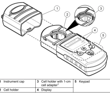
This instrument is a portable filter photometer used for testing water. Refer to Figure 1. This instrument is configured at the factory to measure one or two specific parameters. This instrument is calibrated at the factory. No user calibration is necessary.
Note: This instrument has not been evaluated to measure chlorine and chloramines in medical applications in the United States.
Figure 1 Instrument overview
1 Instrument cap 3 Cell holder with 1-cm
cell adapter1 5 Keypad 2 Cell holder 4 Display
1 Factory installed in some models General information
Section 3 Startup
3.1
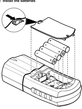
Install the batteries
W A R N I N G
Explosion hazard. Incorrect battery installation can cause the release of explosive gases. Be sure that the batteries are of the same approved chemical type and are inserted in the correct orientation. Do not mix new and used batteries.
Install the batteries as shown in Figure 2. Figure 2 Install the batteries
3.2
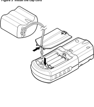
Install the cap cord
Attach the cap cord to prevent loss of the instrument cap. Refer to
Figure 3.
Figure 3 Install the cap cord Startup
Section 4 User interface and navigation
4.1
Keypad description
Figure 4 shows the keypad and gives the key functions. Figure 4 Keypad
1 Power/Backlight key: Sets the power to on and off. Push and hold for 1 second to set the backlight to on or off.
3 Menu key: Enters and goes out of menu mode.
2 Zero/Scroll key: Sets the instrument to zero, scrolls through menu options and numbers
4 Read/Enter key: Starts a sample measurement, selects a menu option, moves the cursor to the next digit
4.2
Display description
Figure 5 Display
1 Numeric display: Measured value
or menu options 4 Menu icon:menu mode. The instrument is in
2 Range icon: Selected range or
parameter 5 Calibration adjusted icon:factory default calibration was The adjusted or a user-entered calibration curve was entered. Refer to the expanded user manual on the manufacturer's website.
3 Range value: Range(s) or
parameters 6 Low battery icon:10%. Flashes when the battery Battery level is level is too low to complete measurements.
Section 5 Operation
5.1
Configure the instrument
1. Push .
2. Push to scroll through the menu options. Push to select an option.
Option Description
SEL Sets the measurement range or parameter. Push to toggle between the measurement ranges or parameters.
00:00 Sets the time in 24-hour format (hh:mm). Push to change the time. Push to change the first digit, then to go to the next digit.
rCL Shows the last 10 measurements recorded. Push to show the recorded measurements (01—most recent measurement, 10— oldest measurement). Push to scroll through the measurements. To select a measurement by number, push to select the number and then . Push to go out of this option.
SCA Refer to Standard calibration adjust on page 17. 3. Push to go back to measurement mode.
5.2
Run a test
W A R N I N G
Chemical exposure hazard. Obey laboratory safety procedures and wear all of the personal protective equipment appropriate to the chemicals that are handled. Refer to the current safety data sheets (MSDS/SDS) for safety protocols.
3. Close the sample cell and clean the optical faces of the sample cell with a lint-free cloth.
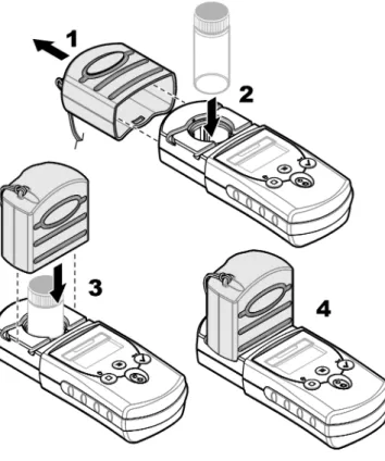
4. Insert the blank sample cell into the cell holder. Make sure to install the blank sample cell in the correct and consistent orientation so that the results are more repeatable and precise. Refer to Figure 6. 5. Install the instrument cap over the cell holder. Refer to Figure 7. 6. Push to set the instrument zero. The display shows "0.000", or
the degree of resolution that was previously selected.
7. Prepare the sample. Rinse the sample cell and cap with the sample three times before the sample cell is filled. Add reagents as specified by the method document.
8. Close the sample cell and clean the optical surfaces of the cell with a lint-free cloth.
9. Insert the sample into the cell holder. Make sure to install the sample cell in the correct and consistent orientation so that the results are more repeatable and precise. Refer to Figure 6. 10.Install the instrument cap over the cell holder. Refer to Figure 7. 11.Push . The display shows the results in concentration units or
absorbance.
Note: The result flashes if the result is less or more than the instrument range.
12.Remove the prepared sample from the cell holder.
13.Immediately empty and rinse the sample cell. Rinse the sample cell and cap three times with deionized water.
Figure 6 Sample cell orientation
1 Orientation mark 2 Sample cell, 25-mm
(10 mL) 3 Sample cell, 1-cm(10 mL)
Figure 7 Install the instrument cap over the cell holder
5.3
Show the recorded measurements
Refer to the "rCL" option in Configure the instrument on page 13. Operation
5.4
Standard calibration adjust
Use the standard calibration adjust (SCA) option when a calibration must be adjusted to meet regulatory requirements. The factory calibration is adjusted slightly with the standard calibration adjust (SCA) option so that the instrument shows the expected value of the standard solution. The adjusted calibration is then used for all test results. This adjustment can increase the test accuracy when there are slight variations in the reagents or instruments.
Note: For instruments with factory-calibrated ranges or methods, the standard calibration adjust (SCA) feature is disabled when a user-entered method is entered into the instrument. To set SCA back to on, set the instrument to the factory default calibration. Refer to Set to the factory default calibration
on page 22.
5.4.1 Adjust the factory calibration with a standard 1. Complete the test procedure for the range to calibrate. For the
sample, use the standard solution concentration given in the test procedure documentation.
Note: If a standard solution concentration is not given in the test procedure documentation, a different known standard can be used.
2. When the test procedure is completed, push . 3. Push until “SCA” shows, then push .
The display shows the standard calibration adjust value. 4. If a different known standard is used, enter the value of the
standard:
a. Push until "Edit" shows, then push .
b. Push to enter the value of the standard. Push to go to the Operation
5.4.2 Set the standard calibration adjust to off To use the factory default calibration again, set standard calibration adjust (SCA) to off.
1. Push .
2. Push until “SCA” shows, then push . 3. Push until "OFF" shows, then push .
Note: To set the SCA function to on again, calibrate with a standard.
5.5
User-entered calibration
This instrument accepts a user-prepared calibration curve. The calibration curve can be from 0 to 2.5 absorbance. Make sure that the calibration curve includes standard values that are less and more than the range of interest.
The instrument range will be the same as the calibration range. For example, when the standards that are used are 1.00, 2.00 and 4.00. The instrument range is 1.00 to 4.00.
There are two options to enter a user calibration curve:
• Enter a calibration curve with standards—The standard solution values are entered with the keypad and the absorbance values are measured.
• Enter a calibration curve with the keypad—The standard solution values and absorbance values are entered with the keypad. Note: If the instrument is set to off or the instrument power is removed before a user-entered calibration curve is completed, the calibration curve is not saved. The instrument automatically switches off in user-entered calibration entry mode after 60 minutes of no activity. User-entered calibrations are completed when the user goes out of calibration (cal) mode or edit mode.
5.5.1 Channel restrictions
A user-entered calibration curve can be entered into any channel that does not contain a factory-programmed curve. These channels have the label:
• “abs” on the instruments that have a single factory calibration Operation
• “1” and “2” on the single wavelength instruments that are not calibrated
Any chemistry that can be done at the instrument wavelength can contain a user-entered calibration in these channels.
5.5.2 Enter a calibration curve with standards
Note: Deionized water can be used for the blank unless the sample is significantly more turbid or has more color than deionized water.
1. Set the instrument to the range to calibrate. Refer to Configure the instrument on page 13.
2. Prepare the blank and the reacted standard solution. Refer to the test procedure. Let the color fully develop.
3. Set the instrument to zero.
a. Insert the blank sample cell in the cell holder. b. Install the instrument cap over the cell holder. c. Push . The display shows “- - - -”, then “0.000”. d. Remove the instrument cap.
e. Remove the sample cell from the cell holder.
4. Push and hold until "USER" and then "CAL" shows, then push .
Note: If "USER" and "CAL" do not show, the factory calibration cannot be changed on the selected range.
5. If "RES" shows on the display, set the resolution.
a. Push . The resolution setting (decimal placement) shows. b. To change the resolution, push , then . Push to save the
6. When "S0" shows on the display, push . Push to enter the blank value, then push .
Note: Push to go to the next digit.
7. When “A0” shows on the display, measure the absorbance of the blank.
a. Insert the blank sample cell in the cell holder. b. Install the instrument cap over the cell holder.
c. Push . The display shows the absorbance value for "S0". d. Remove the sample cell from the cell holder.
8. Push to show "S1".
9. When "S1" shows on the display, push . Push to enter the first standard value, then push .
Note: Push to enter the next digit.
10.When "A1" shows on the display, measure the absorbance of the reacted standard solution.
a. Insert the reacted standard sample cell in the cell holder. b. Install the instrument cap over the cell holder.
c. Push . The display shows the absorbance value for "S1". d. Remove the sample cell from the cell holder.
11.The calibration is completed with two calibration points. If additional standards are necessary for calibration:
a. Push until “Add” shows, then push . b. Do steps 9–10 again to enter more standards. 12.Push two times to go back to measurement mode. 5.5.3 Enter a calibration curve with the keypad At least two data pairs are necessary to enter a user-prepared calibration curve. A concentration value and the absorbance value for the given concentration is necessary for each data pair. A maximum of 10 data pairs can be entered.
Note: This procedure can also be used to change the data pairs in a user-entered calibration curve or factory calibration curve.
1. Set the instrument to the range to calibrate. Refer to Configure the instrument on page 13.
2. Push and hold until "USER" and then "CAL" shows, then push .
Note: If "USER" and "CAL" do not show, the factory calibration cannot be changed on the selected range.
3. Push until "EDIT" shows, then push . 4. If "RES" shows on the display, set the resolution.
a. Push . The resolution setting (decimal placement) shows. b. To change the resolution, push , then . Push to save the
change.
c. To not change the resolution, push .
Note: "RES" does not show on the display of factory-calibrated instruments because the resolution cannot be changed. Only instruments that are not factory calibrated or have "abs" as one of the two ranges show "RES" on the display.
5. When "S0" shows on the display, push . Push to enter the concentration value of the first data pair, then push . Note: Push to go to the next digit.
6. When "A0" shows on the display, push . Push to enter the absorbance value of the first data pair, then push . "S1" shows on the display.
7. Do steps 5–6 again to enter the second data pair (S1 and A1). 8. The calibration is completed with two data pairs. If additional data
pairs are necessary for calibration: a. When “Add” shows, push .
1. Set the instrument to the range to calibrate. Refer to Configure the instrument on page 13.
2. Push and hold until "USER" and then "CAL" shows.
Note: If "USER" and "CAL" do not show, the factory calibration cannot be changed on the selected range.
3. Push until "EDIT" shows, then push .
Note: Calibration points can also be removed in calibration (CAL) mode. 4. Push until the calibration point to remove shows (i.e., S0 or S1),
then push .
5. Push until "dEL" shows, then push .
Note: The minimum number of data pairs is two. When only two data pairs remain, no more data pairs can be removed.
6. Push two times to go back to measurement mode. 5.5.5 Set to the factory default calibration
1. Set the instrument to the applicable range. Refer to Configure the instrument on page 13.
2. Push and hold until "USER" and then "CAL" shows.
Note: If "USER" and "CAL" do not show, the factory calibration cannot be changed on the selected range.
3. Push until "dFL" shows, then push . Operation
Section 6 Maintenance
C A U T I O N
Multiple hazards. Only qualified personnel must conduct the tasks described in this section of the document.
N O T I C E
Do not disassemble the instrument for maintenance. If the internal components must be cleaned or repaired, contact the manufacturer.
6.1
Clean the instrument
Clean the exterior of the instrument with a moist cloth and a mild soap solution and then wipe the instrument dry.
6.2
Clean the sample cells
C A U T I O N
Chemical exposure hazard. Obey laboratory safety procedures and wear all of the personal protective equipment appropriate to the chemicals that are handled. Refer to the current safety data sheets (MSDS/SDS) for safety protocols.
C A U T I O N
Chemical exposure hazard. Dispose of chemicals and wastes in accordance with local, regional and national regulations.
Special cleaning methods are necessary for individual procedures. When a brush is used to clean sample cells, take extra care to avoid scratches on the interior surfaces of the sample cells.
6.3
Replace the batteries
Replace the batteries when the battery power level is low. Refer to
Install the batteries on page 9. Maintenance
Section 7 Troubleshooting
Error Description Solution
E-0 No zero In user calibration mode, a standard solution was measured before the instrument zero was set. Measure a blank solution to set the instrument to zero.
E-1 Ambient light
error1 There is ambient light in the cell holder. Makesure that the instrument cap is fully installed
over the cell holder. E-2 LED error1
The LED (light source) is out of regulation. Replace the batteries. Make sure that the LED in the cell holder comes on when or is pushed.
E-3 Standard adjusterror
• The measured value of the standard solution is more than the adjustment limits. Prepare a fresh standard.
• The standard solution is not within the concentration range that can be used for standard calibration adjust. Prepare a standard with a value at or near the recommended concentrations given in the procedure.
• Make sure that the concentration of the standard solution is entered correctly. E-6 Abs error The absorbance value is not correct or the
user-entered calibration curve has fewer than two points. Enter or measure the absorbance value again.
Error Description Solution
Reading flashes
The reading is more or less than the instrument range.2
If the reading is less than the instrument range, make sure that the instrument cap is fully installed over the cell holder. Measure a blank. If the blank reading is not zero, set the instrument to zero again.
If the reading is more than the instrument range, identify if there is a light blockage in the cell holder. Dilute the sample. Do the test again. For factory-calibrated programs, the maximum and minimum values always equal the factory-calibrated values and cannot be changed.
1 When an E-1 or E-2 error occurs on a measurement, the display shows
“_.__”. The decimal place depends on the chemistry. If the E-1 or E-2 error occurs while the instrument is set to zero, set the instrument to zero again.
2 The flashing value will be 10% over the upper test range limit. Troubleshooting
Section 8 Replacement parts
W A R N I N G
Personal injury hazard. Use of non-approved parts may cause personal injury, damage to the instrument or equipment malfunction. The replacement parts in this section are approved by the manufacturer.
Note: Product and Article numbers may vary for some selling regions. Contact the appropriate distributor or refer to the company website for contact information.
Replacement parts
Description Quantity Item no.
AAA batteries, alkaline 4/pkg 4674300
Cap cord 1 5955900
Instrument cap 1 5954800
Sample cell, 25 mm (10 mL), with caps 6/pkg 2427606 Sample cell, 1 cm (10 mL), with caps 2/pkg 4864302
HACH COMPANY World Headquarters
P.O. Box 389, Loveland, CO 80539-0389 U.S.A.
Tel. (970) 669-3050 (800) 227-4224 (U.S.A. only) Fax (970) 669-2932 orders@hach.com www.hach.com
HACH LANGE GMBH
Willstätterstraße 11 D-40549 Düsseldorf, Germany Tel. +49 (0) 2 11 52 88-320 Fax +49 (0) 2 11 52 88-210 info@hach-lange.de www.hach-lange.de
HACH LANGE Sàrl
6, route de Compois 1222 Vésenaz SWITZERLAND Tel. +41 22 594 6400 Fax +41 22 594 6499