A Multi-Modality Computer-Aided
Framework Towards Postmortem
Identi
fi
cation
Andreas Mang, Jan M¨uller
1and Thorsten M. Buzug
Department of Mathematics and Technology, RheinAhrCampus Remagen, Germany
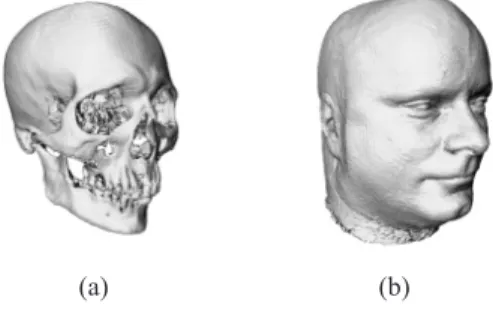
A multi-modality framework for forensic soft-facial re-construction based on computed tomography(CT)and magnetic resonance imaging (MRI) is presented. CT is used to acquire a virtual representation of a skull find and MRI templates provide the desired soft tissue information to produce a facial likeness of a deceased individual. Two main strategies are described. The first is based on a regularized non-linear warping technique using radial basis functions known asthin-plate splines
in 3D space. The second is an automatic segmentation scheme based on active contours, which will provide a facial template that can be morphed onto the CT of the skull find. These approaches are presented in the framework of a forensic workplace.
Keywords: craniofacial reconstruction, forensics, non-linear warping, segmentation, active contours, thin-plate splines, forensic workplace.
1. Introduction
Soft-facial reconstruction on anthropologic or forensic skull finds has been successfully per-formed for many decades. Traditionally, man-ual techniques employing clay or plasticine mod-elled onto the skull are used. The principal goals of this kind of work are twofold. On the one hand, anthropologists are interested in giving an impression of the appearance of fa-mous persons in history — the Stoertebecker face reproduction is an example of such work or giving an idea of a Neanderthaler’s visage as a artwork for a museum’s exhibition. On the other hand, forensic anthropologists are work-ing hand in hand with criminal departments to identify a person by means of a soft-facial re-construction to be published. While the first goal offers some artistic freedom to the sculp-tor, the latter restricts him or her to the informa-tion that has been assembled within the criminal
investigation. If the sculptor, for example, has been supplied with the skull only, without any indication of the structure and color of hair, it is recommended to leave the hair away and to show the reproduction of the face only. Nev-ertheless, one requirement is the same for both goals. Manual face reconstruction requires pro-found know-how in material preparation, a deep understanding of anatomy and anthropology as well as artistic talents and handicraft skills. It is therefore apparent that only a small commu-nity of anthropologic scientists is able to per-form adequate face reconstructions. However, even very experienced anthropologic or forensic sculptors need weeks for this very complicated reconstructive work. For that reason computer-assisted facial reconstruction is becoming more and more important to facilitate and speed up the process of finding the appropriate reproduc-tion of an individual’s facial appearance.
The key to a successful face reconstruction — be it performed manually or computer-assisted — is the anatomical and anthropological knowl-edge of the human facial soft tissue thickness distribution. Research in the field of soft tissue depth measurement has been very active over the last three decades 1]. In order to
estimations, because the bone matrix is consid-ered to support the soft tissue and it is possible to achieve average soft tissue depth at standard-ized points on the cranium (e.g. supraglabella,
nasion, subspinale, supramentale, supraprogo-nion,...).
Acquiring facial soft tissue depth is one of the most widely discussed issues in forensic sci-ences. And, a variety of different measurement strategies were carried out 2, 3, 4]. Most
mea-surements are performed on cadavers. Within these studies, a needle is driven through the skin until the bone is encountered by the tip of the needle. This strategy must result in inac-curacies, because soft tissue depth information is produced as a sparse dataset only and, there are inevitable post-mortem alterations like de-hydration or autolysis, i.e. the breakdown of liv-ing matter by the action of enzymes produced in the cells of the cadaver 1]. Another problem is
the flesh deformation caused by the penetration of the needle. Therefore, current approaches fo-cus on imaging modalities like ultrasound, com-puted tomography(CT)or magnetic resonance
imaging(MRI)to collect the tissue landmarks
from living individuals(see e.g. 5]).
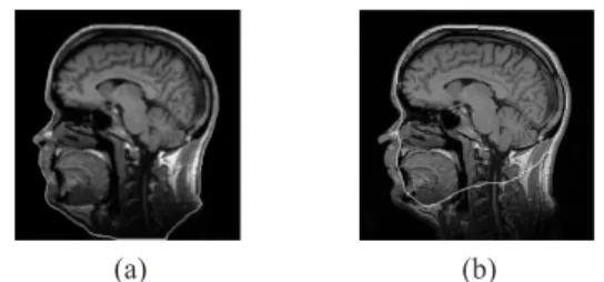
However, many computational methods for the estimation of the individual’s post-mortem fa-cial appearance still suffer from the sparse dis-tribution of depth information across a sub-set of feature points. Even if the soft tissue depth is known at some salient anthropological points, actually, there is an infinity of them. The method proposed in this paper gives a solution to this fundamental problem of sparse soft tis-sue depth information. It is a multi-modality approach combining MR and CT imaging(see
Fig. 1). Due to the fact that MRI especially is
designed to show soft tissue, and the fat signal of the skin is very prominent in MR images,
(a) (b)
Fig. 1.We use(a)CT to acquire a virtual representation of the skull find and(b)MRI to measure facial templates that provide dense soft tissue distributions.
the acquired data inherently carries the desired soft tissue depth information for the entire skull. Hence, we do no longer have to refer to charts providing lacunar depth information at about 20 or 30 standardized landmark positions.
In the application presented here, CT has been used to digitise the discovered skull as CT yields a virtual representation of the skull, which is free of any geometric distortion 6]. As a side
remark, it should be noted that the acquired vir-tual representation of the skull can be employed as a basis for a so-calledrapid prototyping. This technique allows the production of one-to-one plastic casts of the skull. These copies can be utilized for the traditional reconstruction using clay or plasticine, without putting the forensic or archaeological specimen at risk.
However, the aim of this paper is to give an overview on the state of the art of the transition from the traditional manual to the computer-assisted reconstruction techniques, to present a registration-, as well as a segmentation-based face-reconstruction strategy and, finally, to in-troduce a prototype of a computer-based foren-sic workplace.
The paper is organized as follows. (i) the
state of the art of computer-aided reconstruc-tion methods is briefly reviewed in secreconstruc-tion 2.
(ii)the registration-based warping approach is
presented in section 3. It is based on the non-linear warping technique using radial-basis functions known asthin-plate splines(TPS)
ex-tended to 3D space, i.e. a registration method first introduced by Bookstein in 1989 7]. This
landmark-based method, well known from re-gistration studies in medicine, will be used to adjust the acquired MR soft tissue template to the CT cranial bone. To avoid errors induced by misplaced landmarks, a regularized version of this algorithm is used. (iii)The background
to the segmentation-based approach is provided in section 4. It is a semi-automatic segmenta-tion strategy extracting a facial template from MRI to be fit onto the CT data of the skull in a final morphing step. This approach is based on so-calleddeformable models oractive con-tours, respectively, which are well known from image processing applications to locate object boundaries. They were first introduced by Kass, Witkin and Terzopoulos in 1987 8, 9]. (iv)
2. State of the Art in Computer-Aided Craniofacial Reconstruction
This section will focus on principal develop-ments in computer-aided craniofacial reconstruc-tions and briefly review the state of the art. Basically, there are two fundamentally differ-ent methods for facial reconstruction, (i) the
anatomical and (ii) the tissue-depth methods
10, 11]. The first approach is based on
mod-elling the actual face muscles and the latter employing tissue-depth markers at standard-ized positions or landmarks, respectively, on the cranial bone. Anatomical approaches are considered to be extensively time-consuming since each individual muscle needs to be mod-elled separately and must be placed anatomi-cally correct onto the skull 10]. However, most
early computational methods presented in lit-erature are indeed very similar to the manual approach based on dowels representing the soft tissue thickness. In contradiction, some recent approaches take advantage of the entire tissue-depth information.
In 1997 Archer 12]proposed to fit a generic
hi-erarchical B-spline face model to a skull mesh according to predefined virtual landmark dow-els representing the soft tissue thickness. In or-der to overcome drawbacks of applying splines to connect tissue-depth markers and in order to incorporate anatomy-based methods, so called non-uniform rational B-Splines (NURBS) are
proposed in 13]to model the facial surface.
Andersson and Valfridsson 10] likewise
em-ploy landmark dowels defining the distance be-tween skull and skin. All vertices of an arbitrar-ily chosen reference mesh are projected onto the CT representation of the cranial bone corre-sponding to the depth markers. Facial features can be chosen from a library and manipulated in a post-processing step. In order to make the model appear more lifelike, textures can be ap-plied before rendering. One drawback of this approach is that the user needs to manipulate the mesh manually in order to insert or control facial features(e.g. one needs to identify all vertices
defining the outline of the socket to introduce eyes to the mesh). Overall, the resulting faces
appear slightly artificial.
Registration is very prominent in many medi-cal image-processing applications to map one dataset onto another based on a certain cor-respondence between these different datasets. Thus, it is at hand to use registration-based ap-proaches for craniofacial reconstruction as well. Moreover, Subsol and Quatrehomme 14]state
that registration-based approaches are the most promising ones. Quatrehomme et al. 15], 14]
employ single modality matching using a CT scan of the skull find and a CT scan of a refer-ence skull. Additionally, a cast of the referrefer-ence head soft tissue is incorporated to produce a fa-cial approximation of the deceased individual. After registration the reference skull mesh is deformed parametrically according to so called
crest linesonto the discovered skull. Applying the same mapping to the reference head the soft tissue cast is considered to result in the desired facial estimation.
Jones 16] suggests using cross-correlation to
automatically identify feature points in the un-derlying datasets, i.e. the CT cranial bone and a CT reference head, respectively. Subsequently, this resulting correspondence is used to map the soft tissue of the reference head onto the skull find according to a so called distance-field warp function.
The approach presented by B´erar et al. 17] is
similar to those presented by Quatrehomme et al. 15] and Jones 16] concerning the
imag-ing modality used. However, a statistical shape model of skull and face is used instead of deformation-field calculation. Based on CT a database providing different skull surfaces as-sociated with their corresponding skin surfaces is established. A series of tri-linear transforma-tions is applied in order to register the different datas into a subject-shared reference system. In that way, a direct statistical model between face and skull is computed and subsequently used for the reconstruction of the deceased individual’s face upon the CT cranial bone representation. Tu et al. 18] use a set of CT scans to acquire
the average face corresponding to the contri-bution of the chosen deformation mode. Post-processing allows altering features such as nose, eyes and lips and, in addition, texture mapping might be applied in a final step.
Similar to Tu et al. 18], Vandermeulen et al.
19] use multiple reference skin and skull
sur-faces. According to the method presented by Jones 16] a warping of a reference to a target
skull is applied to a reference skin. For each CT in the reference database the facial surface and the skull surface need to be segmented and af-terwards are transformed into signed Distance Transform (sDT) maps. Subsequently, these
warps are applied to the target skull’s sDT. Fi-nally, the zero level set of their arithmetic av-erage is defined as the reconstructed target skin surface.
Claes et al. 20]present an approach similar to
the one proposed by M¨uller et al. 21]. A
statisti-cal facial model is statisti-calculated from different CT scans of living individuals in order to produce an unbiased facial template. Subsequently, this template is fitted onto the digital copy of the skull according to a set of corresponding land-marks. In particular, the method employs a minimal bending thin-plate-spine deformation
(see section 3).
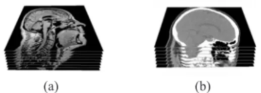
All the methods described above generally yield promising reconstruction results. One draw-back that all these methods suffer from is that they take advantage of CT to acquire the nec-essary soft tissue information. It is quite hard to generate a satisfying reference database, as most cranial CT scans of living individuals are only taken in a limited field of view in order to reduce X-ray exposure(see Fig. 2.). Even with
a low-dose CT scanning protocol, it is not wise — and in many countries simply not allowed — to acquire CT data from healthy volunteers. Therefore, in the methods proposed in the next sections, MRI is used instead of CT to form a soft tissue database.
(a) (b)
Fig. 2.Part of a typical stack of an MRI and of a CT dataset of the head.
K¨ahler et al. 11] present another
registration-based approach. It consists of an anatomy-based virtual head model, incorporating skin and muscles to a scanned skull using statisti-cal data on skull-tissue relationships. Based on Rhine’s tissue-depth tables 2, 3] landmark
dowels are set on the volume CT scan of the skull find and, using non-rigid registration, the reference head is deformed onto the virtual cra-nium. Moreover, underlying muscles are in-corporated into the computed model and thus, this approach seems to be the first one integrat-ing facial expression into computer-aided facial reconstruction. The resulting reconstruction is considerably nice. However, K¨ahler et al. state that, due to the limited number of landmarks,the computed deformation does not properly align the skin to the skull in all places. Therefore, ad-ditional landmark pairs are computed automat-ically by interpolation between existing ones.
Chen 22] presents an interface which might
complement existing methods. In contrast to other approaches, this method does not change features of the face in order to achieve a positive identification. Starting from a central average face, the user has the possibility to choose from a set of related faces the one that resembles the desired face most closely. Each choice will ar-rive in a new set of related faces. Thus, the user is iteratively guided towards the desired fa-cial estimation. This method takes advantage of faces produced by theFaceGen Software De-velopment Kidpackage.
For a comprehensive historical overview of three-dimensional reconstruction methods, see Tyrrell et al. 23] and the book of Clement and Marks
24].
3. 3D Soft Tissue Warping
This section deals with a non-linear registration-based approach to produce a facial likeness of a deceased individual. Particularly, we use a 3D extended implementation of Bookstein’s thin-plate splines(TPS). It falls within the category
of global basis-function methods. In general, it is an interpolation method for non-rigid reg-istration of two sets of homologous anatomical landmark points in an irregular spacing, which need to be identified in both, the MRI and the CT datasets. Subsequently, the MRI dataset carrying the soft facial template is warped onto the CT scan of the cranial bone. As tradi-tional methods require a precise knowledge of the anatomy of the face, the thickness of soft tissue at salient anthropological points and the relationship between various key features, such as eyes, nose, lips, chin, ears, in terms of pro-portion 1], using MRI as a second modality is
at hand, because MRI already contains these features in an anatomically correct relationship.
3.1. Mathematics in Brief
This subsection provides a brief overview of the algebra of regularized 3-dimensional TPS; for a comprehensive coverage of 2-dimensional TPS we refer to Bookstein 7].
A volume is deformed by the interpolation of a so calledcorrespondence function. The general problem can be stated as follows. A function
f must be found, which defines the continuous transformationR
3
!R
3of all pointsp
T of the
target volume (i.e. the CT cranial bone) onto
their corresponding locations pS in the source
volume(i.e. the MRI of the reference head).
f(pT)=pS (1)
The labelstarget and source are related to the role of both volume data sets in the actual imple-mentation. For each voxel in the target volume
T the method calculates the corresponding co-ordinates of the source data S and copies the relevant gray value information found at these locations back to T. Therefore, any voxel of
T contains a gray value even if the volume is enlarged during transformation.
If we consider TPS in a physical manner, they can be compared with a thin metal plate be-ing deformed by external forces. The more the
plate is bent, the higher is the bending energy. If we permit small deviations only, in the ab-sence of gravity, such a plate will bend in such a way that the associated physical bending en-ergy J (eq. (2)) is at minimum 7]. In
gen-eral, this behaviour can be described with one of Duchon’s seminorms of appropriate dimen-sion and order 25, 26]. For the deformation of
a volume dataset a seminorm of third dimension and second order is used 27].
J (f)= ZZZ
R
3
@
2f
@x
2
2 +
@
2f
@y
2
2
+
@
2f
@z
2
2 +2
@
2f
@x@y 2
+2
@
2f
@x@z 2
+2
@
2f
@y@z 2
dxdydz
(2)
Note that in eq.(2)f denotes a scalar field. The
criterion for the vectorfcan be taken simply as the sum of bending energies for each component
x,yandz 26].
J (f)=J (fx)+J ;
fy
+J (fz) (3)
Thus, the correspondence function can be sep-arated into three components, one for each di-mension:
f(pT i)= "
fx(pT i)
fy(pT i)
fz(pT i) #
=pS i; i2f1:::ng
(4)
wherendenotes the number of landmarks in the source and in the target volume, respectively. As stated above, an interpolantfneeds to be de-termined among all possible functions(i)
satis-fying eq.(1) and (ii) minimizing the bending
energy J from eq. (2). Such an interpolation
function must be continuously defined and will map each landmark from the target volumeT
exactly onto its corresponding landmark in the source volumeS; forR
3it is given by
f (xyz)=ap
T
+
n
X
k=1
wk U
; P
k;P
T
(5)
wherea= a0 a1 a2 a3 ]andp= 1xyz].
P= xyz]andPk denotes thex,y andz
The functional of eq.(5)consists of two parts.
The first part determines an affine transforma-tion in 3D and the second part comprises the local elastic deformation. As a straightforward extension of Bookstein’s warping formula 7], it
minimizes eq.(2). The way the volume data is
deformed is controlled by the still unknown pa-rametersaandw. U(r)is the so called
radial-basis function(RBF). Since we are dealing with
a 3D implementation, the RBF is as follows(for
other dimensions than R
3 we refer to Kybic
26]):
U(r)= f(xyz)=krk= p
x2
+y
2
+z
2
(6)
The RBF is the fundamental solution of the so called biharmonic equation Δ2f
= 0 7]; i.e.,
U(r)must satisfy
Δ2U
(r)= @
4
@x
4+ @
4
@y
4+ @
4
@z
4 +2 @
4
@x
2
@y
2
+2 @
4
@x
2
@z
2+2 @
4
@y
2
@z
2
U(r)/δxδyδz)
(7)
whereΔ2denotes the two times iterated
bilapla-cian operator and δ(xyz) is the Dirac
distri-bution.
Further investigations on eq. (5) indicate the
need of boundary conditions to ensure that lo-cal deformations do not affect the whole area.
n
X
k=1
wk =0
n
X
k=1
wk xk =0
n
X
k=1
wk yk =0
n
X
k=1
wk zk =0: (8)
Again,ndenotes the number of landmarks and w = w1 :::wn ]is the set of elastic
param-eters of eq. (5). These conditions restrict the
translation and rotation of the elastic part, as they ensure that terms with a more than linear increase — far away from the landmarks — will not be taken into account. The different coeffi-cients a = a0 a1 a2 a3 ]of the affine and
w = w1 :::wn ]of the elastic part,
respec-tively, from the analytic solution can be deter-mined (5) by solving the following system of
linear equations 27]:
KwT +Pa
T
=v
PTwT =0
(9)
whereKis a matrix containing the values of the radial-basis function, v is a matrix containing the source locations andPis a matrix contain-ing the target landmarks.
Due to the fact that the landmark placement is affected by errors, it is not favourable to force the graph of the interpolation function f
to pass through these erroneous points. Instead, small deviations of the graph of f should be al-lowed. In order to minimize the influence of these errors, a regularized TPS version was im-plemented. We slightly need to change eq.(9)
27].
(K+λI)w
T
+Pa
T
=v
PTwT =0
(10)
Iis an identity matrix of appropriate size andλ denotes the regularization parameter.
3.2. Results and Discussion on 3D Soft Tissue Warping
We have presented a multi-modality approach to the reproduction of a facial appearance for post-mortem identification. It is based on a 3D non-linear warping technique, which allows de-forming an MRI reference template onto the CT data of the cranial bone of a deceased individ-ual. This method is able to provide a solution to the fundamental problem of sparse information about the depth of the soft tissue, as we de-form an acquired reference MRI dataset, which contains the complete information related to the soft tissue to be matched onto the cranial bone. In our implementation the CT scan of the skull represents the target volume T and, accord-ingly, the MRI dataset providing the soft tis-sue template represents the source volumeS. A tri-linear interpolation is used to suppress arte-facts which are likely to occur using a nearest-neighbour interpolation. Our current imple-mentation in a MatLabTM 7 environment takes 10 minutes to map a typical 2563volume dataset
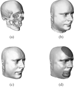
containing 30 landmarks on a 2.2 GHz standard PC. First results can be seen in Fig. 3.
(a) (b)
(c) (d)
Fig. 3.Illustration of the warping of an arbitrarily chosen reference MRI(b)onto a CT cranial bone of an unknown deceased individual(a). In(c)one can see the resulting facial estimation and in(d)the warped dataset
is compared to the initial one.
Adding further individual spatial features like eyebrows, hair and further textures will yield nice reconstruction results. However, since the criminal investigation did not provide us with any further details about hair etc., the finishing make-up step is not carried out.
The main problem of the presented approach is the identification of corresponding landmarks in both datasets. As an option, a split view of sagittal, coronal and axial slices can be used, in order to set the corresponding anatomical landmarks in a three-dimensional spacing(see
Fig. 4.). In some cases, this interaction scheme
does not lead to adequate results. As an exten-sion, the process of landmark setting is
there-Fig. 4.Screenshot of the currently implemented Volume Registration Tool Software.
fore integrated into a virtual three-dimensional visualization. Aditionally, it is recommended to set the homologous points in real world onto the cranial bone or rapid prototyping cast us-ing an optical-trackus-ing system. This leads to the concept of a forensic workplace that will be described in section 5.
According to anthropological and anatomical analysis of the particular skeletal remains, an appropriate MR template needs to be chosen. This is an important step as TPS warping is not capable of all the transformations which are potentially needed, because only those transfor-mations which preserve topology are possible. Therefore, an MRI soft tissue database must be built up containing different templates corre-sponding to ethnic groups, gender, age, weight, physiognomy etc., from which suitable initial templates can be chosen.
4. Soft Tissue Measurements Based on Deformable Models
This section addresses one of the most widely discussed issues in forensic sciences — the soft tissue measurements. In the following a seg-mentation strategy is presented to extract a facial template from a reference MRI dataset. This template provides the desired soft tissue-related information for the entire skull find and can be mapped onto the CT representation of the cra-nial bone in a final morphing step. A similar approach to the one presented below was intro-duced by Rifai et al. 28].
As illustrated in Fig. 5, the visualization of the MR fat signal of the skin yields two sharp boundaries. Detecting these edges will result in the desired soft tissue template. In a first step,
(a) (b)
Fig. 5.This image illustrates the mid-sagittal section(a) and theSobelfiltered mid-sagittal section(b)through the head. As one can see in(b), two sharp boundaries
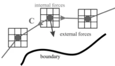
the object shape is mathematically described by so called active contours 8, 9]. These
deformable models are widely used in image processing applications to locate object bound-aries. They move through the image domain by means of energy minimization towards salient features (usually object boundaries) under the
influence of external and internal forces (see
Fig. 6.). Additionally, some internal
regular-ization constraints ensure the regularity of the curve and restrict its bending. Its physical ana-logue is a rubber band, which resists elongating and bending.
Fig. 6.Schematic snake movement through the image domain towards a boundary.
In the following, a brief overview is given of the deformable models used in forensic appli-cation. A detailed review of active contours can be found in 29].
4.1. Mathematics in Brief
Generally, an active contour model is an energy-minimizing spline guided by internal constraint forces and pulled by image forces toward fea-tures such as boundaries 8]. The contour is
initialized with an arbitrary initial shape and lo-cation within the image domain. Due to their intrinsic trend of energy minimization, they de-form into the desired shape and move towards the desired location to align the object bound-ary. There are two different versions of active contours; (i)the geometricorimplicit and(ii)
the parametric or explicit deformable models. In contrast to the parametric models, which are local methods based on an energy minimization procedure guided by external forces, geomet-ric models can be regarded as zero level sets of a higher dimensional function, produced in an energy minimizing way 30]. These implicit
models are based on the level-set method and on the theory of curve evolution, respectively. In
the following, we will speak of active contours in the sense of parametric deformable models. In 2D an active contour is a curveC(s) which
can be described by
C(s)=fx(s)=(x(s)y(s)) j s2 ab]g (11)
where x 2 R
2 denotes the coordinate vector,
which embeds the curve inR
2 ands
2 ab]is
the arc length of C parametrizing the contour. The complete energy functionEguiding the
de-formation ofCwithin the spatial image domain is as follows
E = Z a
b
S(x(s))ds+ Z a
b
P(x(s))ds
!
=min
(12) S(x(s))denotes the so called internal energy,
which defines the physical properties of the con-tour. Particularly, it is composed of two terms
S(x(s))=Ee(x(s))+Eb(x(s)) (13)
S(x(s))=α(s)
@x(s) @s
2
+β(s)
@x
2
(s) @s
2
2
(14)
whereα(s)andβ(s)are non-negative
weighting-parameter functions determining elasticity and rigidity, respectively. Accordingly,γ from(15)
and(16)might as well be altered with respect to
s. For simplicityα(s),β(s)andγ(s)are
com-monly implemented as constant non-negative regularization parameters.
The first order term in(14) makes the contour
behave like a membrane(i.e. it resists
stretch-ing), while the second term in(14)makes the
contour act like a thin plate(i.e. it resists
bend-ing) 31]. Correspondingly, the first derivative
in(14) defines the deformation along the
tan-gential direction atx(s)and the second
deriva-tive defines the deformation of its curvature at that point. Eeis at minimum, if the first
deriva-tive disappears, i.e. x(s) = const. Thus, Ee
tends to shrinkx(s) towards a single location.
The bending energyEbrepresents the curvature
and, therefore, it tends to be smoothenC.
P(x(s))from eq.(12)denotes the potential
as-sociated to the external forces along C. It is computed directly from the imageI(xy); if we
consider a grey level image with continuous po-sition variables(xy)typical potential energies
P(xy)=;γ jrI(xy)j
2
(15)
P(xy)=;γ jrGσ(xy)rI(xy)j
2
(16)
where γ is a non-negative weighting parame-ter, r is the gradient operator andGσ(xy)
rI(xy)denotes the convolution between the
gradient of the imageI and a two-dimensional Gaussian functionGσ(xy)with standard
devi-ation σ. The larger the standard deviation σ, the larger is the capture range of the external energy. Regardless of the choice of the exact external energy, the method for minimizing the
E in (12)is the same. Finding a curve C that
minimizes the associated energy functional is a so calledvariational problem 29]. Each curve
that balances the internal and external energies needs to satisfy the following Euler-Lagrange equation:
@ @s
α(s) @x(s)
@s
;:::
:::; @
2
@s
2
β(s) @
2x
(s) @s
2
;rEx =0 (17)
In order to find the solution of(17)x(s)is made
dynamic and thus, must be treated as a function of time t. The partial derivative of x(s) with
respect totneeds to be set equal to the left-hand side of equation(17) 29]. This results in
η@x(st) @s
= @ @s
α(st)
@x(st) @s
; @
2
@s
2
β(st) @
2x
(st) @s
2
; rP(x(st)):
(18)
The coefficient η needs to be introduced to match the units of the left-hand side to the units on the right-hand side. As soon as the solution of x(st), which must be found numerically,
converges, i.e. the contour reaches a steady state, all energies are at equilibrium. Accord-ingly, the left-hand side of (18) vanishes and,
hence, the solution of equation(12)is found.
4.2. Results and Discussion on Deformable Models in Forensic Applications
The current implementation is based on a greedy algorithm. This method that computes the so-lution of(12), was first proposed by Williams
et al. 32]. As mentioned above, the underlying
problem is the segmentation of the head’s soft tissue, as dense information about soft tissue depth is required in the forensic application. The algorithm is organized as a two-step method. In the first segmentation step, the contour shrinks from the image boundary onto the outer bound-ary of the support of the image, which is essen-tially the skin surface of the head(see Fig. 7(b)).
This first step is typically uncritical. However, as the skin thickness is needed, the inner bound-ary of the skin’s fat signal is required as well. Here it is proposed to use the result of the first segmentation step as initial contour of the sec-ond step. To start further iteration towards the inner skin boundary, the high-pass filter signal of the outer skin edge is erased in the filtered im-age, i.e. the external energy at the corresponding image area is forced to be zero. In that way, the curve evolves to the inner boundary of the MR fat signal of the head. This procedure yields en-couraging results at most locations. However, due to blurry edges, sparse edge information and high curvature next to the nasion and the chin, the results in these areas are unsatisfactory(see
Fig. 7(b))and need interaction.
(a) (b)
Fig. 7.First segmentation results of the template providing the desired information of the depth soft
tissue. The active contour is coloured white.
A clear way to improve segmentation results is to use CT instead of MRI to obtain the de-sired tissue-depth information, since CT pro-vides the desired template as well, without con-taining complex tissue structures. Nevertheless, we strongly recommend using MRI instead of CT, as we do not believe that it will be possi-ble in future to create a sufficiently large CT database of facial soft tissue templates.
Considering the advantages of geometric de-formable models such as their intrinsic behaviour and their parameterization independence 33],
set-based approach which is currently mented. Moreover, a three-dimensional imple-mentation of the presented method will pos-itively affect segmentation results, as the de-formable model is additionally influenced by edge information present in neighbouring slices of the volume dataset.
Once the MR template is extracted, it might be matched onto the CT representation of the cranial bone with the thin-plate spline method described in section 3. However, as an option the template may be morphed with a slightly modified algorithm utilized for the segmenta-tion. The key idea is to equip a curve to be iterated with the active contour algorithm with one further attribute in addition to rigidity and elasticity, which is the soft tissue thickness. In that way, a curve can be morphed onto the CT data of the skull find that inherently carries the skin information.
As a side remark, it should be noted that this morphing step will face problems in the pres-ence of dental artefacts in the CT reconstruction of the cranial bone. These CT-metal artefacts, which occur due to strong beam hardening, re-sult in artificial stripes when a standard filtered backprojection is used for image reconstruction
(see Fig. 8). However, since the presence of
stripes caused by metallic cavity fillings in teeth is a diagnostic problem in CT as well, itera-tive reconstruction methods are currently im-plemented to reduce metal artefacts 34].
(a) (b)
Fig. 8.Computed Tomography of a cranial bone(a) with dental artefacts and(b)without dental artefacts.
5. Forensic Workplace
As facial reconstruction requires a large amount of anatomical and anthropological knowledge, the main purpose of this part is to facilitate the process of creating an anatomically correct face reproduction. Besides the software modules
described in the sections above, the presented prototype of aforensic workplaceconsists of a skull fixation unit, a PC with volume rendering extension card and an optical navigation system
(Fig. 9.).
Fig. 9.The forensic workplace.
Due to the large and detailed datasets, the PC features a volume rendering card consisting of several highly specialized processors and a huge amount of memory to guarantee a steady work-flow. In this case, it is a VolumePro 1000 card from TeraRecon, which is one of the leading volume rendering solutions at present. The clamp device for the cranial bone is inspired by a medical solution used for the fixation of the head during brain surgery. In order to sim-plify the interaction between forensic scientist and virtual data, the manipulation is done in real world using an optical navigation system. As the coordinates of the pointing device are up-dated several times per second, the opportunity of real-time interaction is provided.
The workflow of a reconstruction is as follows.
(i) the cranial bone is fixed in the clamp and (ii)guided by the software, the user iteratively
identifies predefined landmarks on the cranium using the pointing device; (iii) a proper MRI
dataset, which already contains the correspond-ing landmarks, is chosen from the database and
(iv)the warping is computed;(v)textures might
be applied to make the reconstruction results look more lifelike.
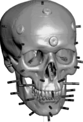
The segmentation-based method presented in section 4 will also be embedded into the foren-sic workplace. It will be combined with an orig-inally B-spline-based reconstruction approach, that made use of the optical-tracking system to set virtual dowels representing the soft tissue depth at salient points on the CT representation of the cranial bone Fig. 10. According to Archer 12], B-splines are used to interpolate the soft
tissue thickness between these dowels in order to produce a facial estimation.
Fig. 10.Dowels representing the soft tissue thickness at standardized locations on the cranial bone.
As mentioned throughout the paper, the virtual dowels provide too sparse information on the soft tissue thickness. However, the methods described in the sections above, benefit from a combination with the dowels. The virtual dow-els might be used to guide the shrinking process of the augmented contour, carrying the soft tis-sue related information. In addition, the dowels can be used to avoid rotation of the augmented contour, while morphing onto the skull. Fur-thermore, the dowels prevent the deformation of protruding parts of the face, such as the nose.
6. Conclusion
A framework has been presented towards the fa-cial reconstruction for post-mortem identifica-tion. The methodology includes a registration-based approach, which allows deforming a ref-erence MRI soft tissue template onto the CT representation of the skull find. Furthermore,
a method for segmenting the soft tissue depth-related information from MRI was presented. It has been demonstrated that the deformation of an MRI template based on non-linear warping leads to encouraging results and, moreover, it has been shown that active contours are capable of extracting a soft-facial template from MRI providing the required information on the depth of dense soft tissue for the entire CT represen-tation of the cranial bone. Both, the registration as well as the segmentation-based approach, are integrated into a prototype of a forensic work-place that is inspired by the workflow of navi-gated surgery.
As MR and CT datasets are usually acquired from a lying individual, the facial shape, and therefore, the measured soft tissue depth, may differ from the one measured in upright position 1]. Studies will have to show to what extent
these inaccuracies really affect reconstruction results.
Forensic facial reconstruction is a research area between art and science. Therefore, computer-aided craniofacial reconstruction is actually a way to simplify the reconstruction procedure, but it will not be capable of replacing the intu-ition of the artist, which is highly demanded to achieve positive identifications.
7. Acknowledgements
The authors would like to thank Markus Pung and Stephan Theisen for their work in the field of image-guided navigation for forensic facial reconstruction. Additionally, we would like to thank Dirk Thomsen for the kind support in CT-image acquisition and Prof. Dr. Dr. J¨urgen Ruhlmann for providing us with MR images.
References
1] G. QUATREHOMME ANDG. SUBSOL, Classical non-computer-assisted craniofacial reconstruction. In
Computer-Graphics Facial Reconstruction, chapter 2, page 1532. Academic Press, USA, April 2005.
3] J.S. RHINE ANDC.E. MOORE, Facial Reproduction: Tables of Facial Tissue Thickness of American Caucasoids in Forensic Anthropology, University of New Mexico, Technical Report Maxwell Mu-seum, Technical Series 1, Albuquerque,(1984).
4] G.P. HELMER, S. ROHRICHT, C. PETERSON ANDF. MOHR, Assessment of the reliability of facial
recon-struction,Forensic Analysis of the Skull, Wiley-Liss, 17(1993), pp. 229–246.
5] V. PHILLIPS ANDN. SMUTS, Facial reconstruction: Utilization of computerized tomography to measure facial tissue thickness in a mixed racial population,
Forensic Sci. Int., 83(1996), pp. 51–59.
6] T.M. BUZUG, P. HERING ANDR.P. HELMER, 3D to-mography as a basis for anthropological and foren-sic facial reconstruction, K. Sigl and K. Pr¨ufer
Proceedings of the 1st International Conference
on Reconstruction of Soft-Facial Parts, Postdam, November,(2003), pp. 91–108.
7] F. BOOKSTEIN, Principal warps: Thin plate splines and the decomposition of deformations, IEEE Transactions on Pattern Analysis and Machine In-telligence, 6(11), June,(1989), pp. 567–585.
8] M. KASS, A. WITKIN AND D. TERZOPOULUS, Snakes: Active contour models,International Jour-nal of Computer Vision, 1(4),(1987), pp. 321–331.
9] D. TERZOPOLOUS, On matching deformable
mo-dels to images,Topical Meeting on Machine Vision, Technical Digest Series(1987), pp. 160–163.
10] B. ANDERSSON ANDM. VALFRIDSSON, Digital 3D Facial Reconstruction Based on Computed Tomo-graphy,Link¨opings Universitet, Sweden, February, (2005).
11] K. K ¨AHLER, J. HABER ANDH.P. SEIDEL, Reanimat-ing the dead: Reconstruction of expressive faces from skull data, ACM TOG (SIGGRAPH Confer-ence Proceedings), 22 July,(2003), pp. 554–561.
12] K.M. ARCHER, Craniofacial Reconstruction Using Hierarchical B-Spline Interpolation, University of British Columbia, August,(1997).
13] S.L. DAVY, T. GILBERT, D. SCHOFIELD AND M.P. EVISON, Forensic facial reconstruction using
com-puter modelling software, JG. Clement and MK. Marks, Computer-Graphic Facial Reconstruction, 10 Academic Press, USA, April.(2005)pp. 183– 196.
14] G. SUBSOL ANDG. QUATREHOMME, Automatic 3D facial reconstruction by feature-based registration of a reference head, JG. Clement and MK. Marks,
Computer-Graphic Facial Reconstruction, 5 Aca-demic Press, USA, April,(2005), pp. 79–101.
15] G. QUATREHOMMEet al., A fully three-dimensional method for facial reconstruction based on de-formable models, Journal of Forensic Sciences, 42(1997), pp. 649–625.
16] M.W. JONES, Facial reconstruction using volumet-ric data,Proceedings of the6thInternational Vision
Modelling and Visualisation Conference, Stuttgart, November,(2001), pp. 136–142.
17] M. B´ERAR, M. DESVIGNES, G. BAILLY AND Y. PAYAN, 3D Statistical Facial Reconstruction,
Pro-ceedings of the 4th International Symposium on
Image and Signal Processing and Analysis (ISPA), Zagreb, September,(2005), pp. 365–370 .
18] P. TU, RI. HARTLEY, W.E. LORENSEN, M. ALLYASSIN, R. GUPTA AND L. HEIER, Face
re-constructions using flesh deformation modes ,JG. Clement and MK. Marks, Computer-Graphic Fa-cial Reconstruction, 8 Academic Press, USA, April
(2005), pp. 145–162.
19] D. VANDERMEULEN, P. CLAES, P. SUETENS, S. DE
GREEF ANDG. WILLEMS, Volumetric Deformable
Face Models for Cranio-Facial Reconstruction, Pro-ceedings of the 4th International Symposium on
Image and Signal Processing and Analysis (ISPA), Zagreb, September,(2005), pp. 353–358.
20] P. CLAES, D. VANDERMEULEN, P. SUETENS, S. DE GREEF ANDG. WILLEMS, Statistically Deformable
Face Models for Cranio-Facial Reconstruction, Pro-ceedings of the 4th International Symposium on
Image and Signal Processing and Analysis (ISPA), Zagreb, September,(2005), pp. 347–352.
21] J. M ¨ULLER, A. MANG AND T.M. BUZUG, A Template-Deformation Method for Facial Repro-duction,Proceedings of the4thInternational
Sympo-sium on Image and Signal Processing and Analysis (ISPA), Zagreb, Semptember,(2005), pp. 359–364.
22] T.-P.G. CHEN, 1,001,001 faces, a configural face navigation interface,University of British Columbia, June,(2003).
23] A.J. TYRRELL, M.P. EVISON, A.T. CHAMBERLAIN
ANDMA. GREEN, Forensic three-dimensional facial
reconstruction: Historical review and contemporary developments, Journal Forensic Science, 42 (4) July,(1997), pp. 653–661.
24] J.G. CLEMENT AND M.K. MARKS, Computer-Graphic Facial Reconstruction, 10Academic Press, USA, April,(2005).
25] J. DUCHON, Interpolation des fonctions de deux vari-ables suivant le principe de la flexion des plaques minces,RAIRO Analyse Num´erique, 10(1976), pp. 5–12.
26] J. KYBIC, Elastic Image Registration using Para-metric Deformation Models, Ecole Polytechnique F´ed´erale de Lausanne, Lausanne, Switzerland,
(2001).
27] K. ROHR, H.S. STIEHL, R. SPRENGEL, T.M. BUZUG, J. WEESE ANDM.H. KUHN, Landmark-based elastic
registration using approximating thin-plate splines,
IEEE Transactions on Medical Imaging, 20 June,
(2001), pp. 526–534.
28] H. RIFAI, I. BLOCH, S. HUTCHINSON, J. WIART AND
L. GARNERO, Segmentation of the skull in MRI
29] C. XU, D.L. PHAM ANDJ.L. PRINCE, Image Segmen-tation Using Deformable Models, JM. Fitzpatrick and M. Sonka, Handbook of Medical Imaging, 2
(3), SPIE press, May,(2000), pp. 129–174.
30] M. WEI, Y. ZHOU ANDM. WAN, A fast snake model based on non-linear diffusion for medical image segmentation,Computerized Medical Imaging and Graphics, 28(3),(2004), pp. 109–117.
31] N. PARAGIOS, O. MELLINA-GOTTARDO AND V.
RAMESH, Gradient vector flow fast geodesic
ac-tive contours, International Journal of Computer Vision, 1(2001), pp. 67–73.
32] D. WILLIAMS, D.J. SHAH ANDM. SHAH, A fast algo-rithm for active contours and curvature estimation,
CVGIP: Image Understanding, 55 (1), January,
(1992), pp. 14–26.
33] X. HAN, C. XU ANDJ. PRINCE, A Topology Preserv-ing Level Set Method for Geometric Deformable Models,IEEE Transaction on Pattern Analysis and Machine Intelligence, 25(2003), pp. 755–768.
34] M. OEHLER, L. PFAFFMANN ANDT.M. BUZUG, Arte-fact Suppression in Computed Tomography using Iterative Reconstruction Methods,Biomedizinische Technik 50, 1 N¨urenberg,(2005), pp. 1130–1131.
Received:December, 2005
Accepted:February, 2006
Contact address:
Thorsten M. Buzug Department of Mathematics and Technology RheinAhrCampus Remagen S¨udallee 2, D-53424 Remagen, Germany e-mail:[email protected]
ANDREASMANGis an undergraduate student at the Department of Mathematics and Technology at the RheinAhrCampus Remagen, Ger-many. Since 2002 he has been studying medical engineering at the RheinAhrCampus Remagen, University of Applied Sciences Koblenz. In 2003 he joined the Research Group of Prof. T. M. Buzug in the field of image processing for craniofacial reconstruction. He worked on the source reconstruction software package CURRY at Compumedics Germany GmbH during his practical term for about seven months in 2004/2005. He is member of the DGBMT(German Society of
Biomed-ical Engineering)of VDE.
JANM ¨ULLERis an undergraduate student at the Department of Math-ematics and Technology at the RheinAhrCampus Remagen, Germany. Since 2002 he has been studying medical engineering at the RheinAhr-Campus Remagen, University of Applied Sciences Koblenz. In 2003 he joined the Research Group of Prof. T.M. Buzug in the field of image processing for craniofacial reconstruction. Currently he is working on iterative reconstruction algorithms in the field of computed tomogra-phy. He is member of the DGBMT(German Society of Biomedical
Engineering)of VDE.
THORSTENM. BUZUGis a Professor at the Department of Mathemat-ics and Technology, RheinAhrCampus Remagen, Remagen, Germany. He was born in L¨ubeck, Germany, in 1963. He received his Diplom-Physiker degree in 1989 and his Ph.D. in Applied Physics in 1993, both from the Christian-Albrechts-University of Kiel, Germany, where he worked in the field of signal processing applied to chaotic systems. From 1993 to 1994 he held a postdoctoral position at the German Federal Armed Forces Underwater Acoustics and Marine Geophysics Research Institute, where he worked on image acquisition and pro-cessing techniques for SONAR applications. In the end of 1994 he joined the Philips Research Laboratories Hamburg, Germany. He was the leader of the Philips Research Cluster Medical Image Processing and responsible for several projects in that field. In October 1998 he was appointed as professor of Physics and Medical Engineering at the RheinAhrCampus Remagen. From 2000 to 2004 he was head of the Academic Development Committee of the RheinAhrCampus Remagen. Since 2005 he is head of the Joint Council of Campus Departments and director of the Institute of X-Ray Optics(IXO)at RheinAhrCampus
Remagen. He has published numerous journal articles, conference papers and books. He is member of Scientific Board of the Journal “Befund: Krebs” and of the Advisory Committee “Stiftung Sparkasse Zukunft Kreis Ahrweiler”. He is member of the German Physical So-ciety(DPG), German Society of Biomedical Engineering(DGBMT),