Cell Library Creation using ALF
Assim Sagahyroon
1and Maddu Karunaratne
2 1American University, Sharjah, UAE2University of Pittsburg, Johnstown, Pennsylvania
The design of Integrated Circuit(ASICs and SoCs) typi-cally relies on the availability of a library consisting of predefined components called technology cells. Silicon vendors use proprietary formats to describe technology cells and macro modules in conjunction with numerous translators to feed technology library data to Electronic Design Automation (EDA) tools. Multiple grammar formats are used to represent various aspects of the cells in the same technology library, such as behavior for simulation, timing parameters for synthesis, physical data for layout, noise parameters for signal integrity checks, etc. In addition, most of these formats are highly tool-oriented and are not grammatically consistent. In this paper we will discuss the newly adopted IEEE 1603–2003 Advanced Library Format (ALF) standard which eliminates such drawbacks. This standard defines a grammar for accurate and comprehensive modeling of technology libraries and macro modules in order to bridge the growing gap between new design rules and the analysis required for complex high-end IC implementations.
Keywords: ASIC, SoC, Technology Cells, Advanced Library Format(ALF).
1. Introduction
Designing integrated circuits(ICs)and System
on Chip(SoC) using 0.18-micron and smaller
process technologies pose tremendous challen-ges for design teams. Perhaps the most signifi-cant problem with existing design environments is that power, timing, and signal integrity ef-fects are strongly interrelated in the nanometer domain, but conventional point-solution design tools do not have the capability to consider all of these effects and their interrelationships con-currently. For example, the number of silicon failures caused by signal integrity problems is on the rise due to the lack of existing design tools and methodologies that can address these issues effectively1].
In this deep submicron era, an increasing num-ber of effects that were previously insignificant are becoming first order and can no longer be ignored in present day IC design requirements. The complex, second-order effects for new sub-wavelength nanometer processes(residence,
in-ductance, crosstalk, leakage, electromigration, etc.) are modeled in abstraction, mostly for the
physical layer. This results in additional number of design iterations that may be required in or-der to fix problems found very late in the design cycle. Therefore it is becoming much more difficult to design in the nanometer era whilst maintaining expected performance, power(
sta-tic and active), area, design cycle time,
man-ufacturability and cost scaling. These effects need to be dealt with at all levels: technology process, data extraction and library modeling, logic synthesis, circuit design, place and route, clock distribution, verification, and final test and assembly. Therefore, architecting a tech-nology cell library with these effects in mind can help reduce their adverse impact on chip design
2].
of available technology for competitive advan-tage. Moreover, with supply voltages reducing to one volt or less, voltage drops due to high switching currents would cause unexpected sig-nal delays in critical circuit areas. Such issues need additional point tools to analyze them and safeguard the designs by applying incremental changes during design and physical implemen-tation phases. Unless the analysis and repair capabilities are combined into the same EDA tool, for high-end designs in SoC domain, the iterative process of analysis and repair of sig-nal integrity violations become inefficient. In general, the quality of results depends on the quality of the analysis models that are provided to the tool. A case in point, for signal noise and electromigration, there was no library model-ing language available in the industry that could represent the characterization data. ALF(IEEE
standard 1603–2003, approved Sept. 2003) is
the only standard language available to model such details and essential information into tech-nology cell libraries and macro modules. Other modeling languages, though none of them are IEEE standards, are being enhanced to accom-modate such information to be in par with ALF. At present, ALF is the only available indus-try standard that can describe not only timing, power and noise, but also electromigration, hot electron, antenna and other factors in consistent and comprehensive formats.
2. IC Design Flow
In this section, we will briefly describe a typi-cal design flow for ASIC and IP modules. For a comprehensive discussion of this flow, readers are referred to3].
The design flow begins with a behavioral spec-ification of the design. The specspec-ification doc-ument can be an elaborate docdoc-ument that in-cludes delay, area and power constraints, and other criteria that might govern the design. At the behavioral level, we are modeling function-ality of the design in the form of an input-output model that suppresses the details about gate and physical level implementations. At this stage, the intended input- output relationship can be verified using functional simulation. Next, ei-ther a Behavioral Synthesis tool or a human designer transforms the behavioral description
into a Register Transfer Level (RTL)
descrip-tion. At this level, the design is described as a dataflow model that will implement the in-tended digital circuit. That is, this level con-sists of components and their interconnections. Logic synthesis tools are then used to convert the RTL description to a gate-level netlist. In essence, the gate-level netlist is a technology-independent description of the circuit in terms of a netlist of standard cells such as gates, flip-flops, latches, and sometimes multiplexors, counters and interconnections between them. The synthesis tool ensures that the generated netlist meets timing, area and power specifica-tions. The process of transforming this generic cell-based logic network into a vendor-specific network is known as library binding or tech-nology mapping. The library contains a set of parameterized technology cells. These cells are usually provided with their physical layout, tim-ing models, behavioral models, etc. The netlist is then input to an automatic Place and Route tool to generate the physical layout. The layout is verified and then fabricated as an IC chip.
3. Technology Cell Libraries
Design approaches can generally be classified into custom and semi-custom designs. Com-pared to the custom design approach, the com-plexity and cost of designing an IC is greatly reduced in the semi-custom design approach. The semi-custom designs use predesigned tech-nology cells and (much larger) macro
mod-ules that are usually optimized, well-designed, and well-characterized. EDA tools are used by designers to choose among the various avail-able cells/modules and to interconnect them
to achieve the desired design functionality and performance. Semi-custom designs can fur-ther be subdivided into two categories: array-based design and cell-based design. Array-based designs use a prefabricated matrix of non-connected components namedsites; these sites are then interconnected to create a circuit with the desired functionality. This paper is mainly concerned with semi-custom design that is cell-based, for a detailed discussion of array-based design, readers can refer to4]. Cell-based
targets. Each cell in the library is typically pa-rameterized in terms of area, delay, and power. In cell-based designs, engineers can use stan-dard cells and/or macro cells. Examples of
standard cells are basic logic gates such as in-verters, NAND gates and NOR gates. Examples of macro cells include memories and complex datapath components such as adders and multi-pliers.
Each cell in an ASIC library must contain at least the following information3]:
A circuit schematic A physical layout A behavioral model A detailed timing model A wire-load model A routing model A cell icon A test strategy A power model
An IC designer needs a high-level or behavioral model for each cell to avoid time consuming and detailed simulation, especially at the ini-tial design iterations. On the other hand, for example, a detailed timing model for each cell is needed in order to assess the performance of the overall design. Silicon Foundries, who are the “library providers”, strive to provide their customers with accurate and complete charac-terization of every cell in their library. In or-der to characterize a cell, the detailed electrical parasitics of cell layout are extracted and the behavior of each library cell is characterized over a range of output loads and input rise/fall
times. Some of the parameters tracked dur-ing this process are propagation delay, output rise/fall times and peak/average current. The
characterization can then be represented as a closed-form equation or in the form of a look-up table of input rise/fall times, output
load-ing, and device characteristics inside the cell. These library elements are typically simulated using different process scenarios and operating conditions to guarantee reliable operation, suffi-cient design margin and scalability4]. The sets
of operating conditions may specify parameters such as the process, temperature, voltage and RC tree models. These can be used during syn-thesis and timing analysis of the design. Before
ALF, contrasting formats had to be used to rep-resent the same technology cells to suit different applications, even from the same EDA vendor. For example: A technology library is described as a logic library and a physical library. An ex-ample of such a commercially available library is theSynopsys technology library5]. This
li-brary can be categorized into two libraries: a logic library and a physical library. The logic library contains information relevant only to the synthesis process and is used for synthesis and design optimization. This information includes pin-to-pin timing, area, pin types and power; no physical information is given in the logic li-brary. On the other hand, the physical library contains the physical characteristics of the cell such as physical dimensions of the cell, layer information and orientation of cells.
Cell libraries are evaluated by considering vari-ous aspects of library characteristics such as its synthesis efficiency, robustness, portability, us-ability, quality, timelines, custom support, and cost. In conclusion, cell libraries determine the overall performance of the optimized logic. A well-characterized cell library will result in fast and efficient designs, whereas a poorly designed and characterized library will, no doubt, de-grade the performance of the end product.
4. A Comprehensive Library Format: The Case for ALF
In the previous section, the authors discussed the role of the library in the design flow and its importance. In this nanometer era, and as the complexity of IC design progresses, one of the main challenges iscell library development. This process has become very critical and of-ten whether to start off on a new design may depend on the availability of an acceptable cell library for that application. Hence, there is an increased need for library accuracy and consis-tency across design flows6].
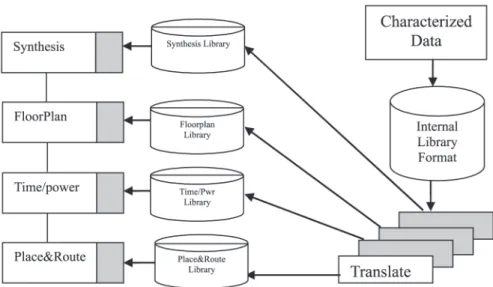
Currently, many large ASIC and semiconductor companies use internally developed formats to describe the technology cells and macro mod-ules in conjunction with numerous translators to feed technology library data to EDA tools
7–8]. Sometimes, multiple formats are used
Fig. 1.Current Library Creation Strategies.
same technology library, such as functionality for simulation, timing parameters, physical de-sign characteristics, de-signal integrity data, etc. Also, most of these formats are highly tool-oriented; that is, it is often the case that a silicon vendor company has to generate several differ-ent library formats for the same technology fam-ily, for different tools to be used in the different parts of the design flows. Figure 1 summarizes the present approach to library creation and us-age9].
To control the complexity of deep submicron design flows and the expensive library creation
(repetitive change of tool-specific libraries), an
industry-wide standard for library format was needed. The advantages include: reduced cost, improved quality, portability and an appreciable time saving in library creation and validation. The Advanced Library Format(IEEE standard
1603) alleviates the aforementioned problems
by providing a modeling language and seman-tics for the functional, physical, and electrical performance description of technology-specific libraries for cell-based and macro-module-based designs. ALF provides models with functional and performance information including simula-tion, synthesis, timing analysis, power analysis and signal integrity characteristics. The basic goals of the proposed format can be summarized as follows10]:
Simplicity: library creation process must be easy to understand and should not become a cumbersome process.
Generality: tools of any level of sophistica-tion must be able to retrieve necessary infor-mation from the library.
Expandability: for early adoption and future enhancement possibilities.
Flexibility: the choice of keeping the in-formation in one library or in separate li-braries must be in the hand of the developer; it should not be mandated by the standard.
Efficiency: the complexity of the design in-formation requires that the process of re-trieving information from the library does not become a bottleneck.
Ease of implementation: unambiguous de-scription and accuracy of contents.
Acceptance: preference for the new standard library over existing libraries.
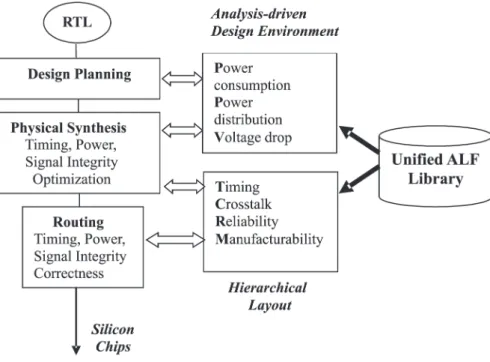
Fig. 2.An Integrated Design Environment Enabled by ALF.
as an elaborate and formalized version of the
databook. The purpose here is quite different from hardware description languages such as VHDL, where the language is designed mainly to specify functionality without other aspects of hardware implementation. In summary, the ALF standard paves the way for efficient de-sign environments such as the one depicted in Figure 2. However, the fact that ALF is richer in grammar and semantics when compared to VHDL and Verilog, makes developing parser and compilers for ALF a demanding task. In the shown environment, an RTL design de-scription is transformed into a netlist by an RTL synthesis tool. The netlist is a collection of cell instances interconnected to form the cir-cuit. The application can use the ALF library to find the library elements needed to map the RTL description into a netlist containing instances of cells. An equivalence checking tool can be used to determine if the RTL-to-netlist transforma-tion has been done correctly, by comparing the RTL design description with the netlist. This application can use the same ALF library used by the synthesis tool. HDL-based simulation tools can be used to verify that both, the RTL design description and the netlist, behave as ex-pected in response to a given stimulus. The simulation tool can use the same ALF cells or higher level ALF modules(for simulation
effi-ciency)10]. During cell placement and
inter-connect, ALF cell models containing abstract physical information, such as the size and shape of the cell, and the location, size, and shape of the cell pins and routing blockages, which are pertinent for layout, can be used. Also, abstract information concerning implementation details
(artwork)within the cell can be represented in
ALF; for example, the area, perimeter and con-nectivity of artwork on specific metal layers. This information is pertinent for manufactura-bility, such as antenna rules and metal density checks. In addition to cell models, technology rules for routing can also be represented in ALF, such as constraints for the width and length of routing segments, and the distance between vias
10]. In addition to functionality and layout,
the ASIC or Integrated Circuit (IC) also has
to meet electrical performance constraints such as timing constraints. Other aspects of electri-cal performance, such as power consumption, signal integrity and reliability, can be modeled using ALF. Also, cell models in ALF support characterization data for timing, power, signal integrity and reliability. After placement and routing, parasitic effects can be extracted and presented in a file using the standard parasitic exchange format. An interconnect model in ALF can describe, using a statistical wire load model(used to statistically estimate parasitics),
esti-mated routes, or an interconnect analysis model. The interconnect analysis model specifies the desired level of granularity for the parasitics and the calculation of timing, noise, voltage, or current based on instances of parasitics and on an electrical model of a driver cell. The data re-lated to the electrical model of a particular driver cell can be represented in ALF as a part of cell characterization data. The end result is a single and unified library where entities are modeled at the functional, electrical and physical levels. A library that has all timing, power, signal in-tegrity, layout, etc, information allowing for the creation of a system that can compute across any tool precise and consistent parameters.
5. Design Descriptions in ALF
ALF consists of several distinguishing char-acteristics, such as Completeness, Simplicity, Orthogonality, Expressiveness, and Reusabil-ity. Descriptions in ALF arecompleteand self-contained. The standard supports the complete description of technology data, as well as how that data is to be processed or used by the ap-plications. In contrast, other languages simply allow the presentation of data leaving their in-terpretations and usage to relevant applications, which may lead to erroneous assumptions. ALF achieves this self-contained characteristic by means of arithmetic models used for calculat-ing mathematically describable quantities; geo-metric modelsthat describe the shape of physi-cal objects;Boolean expressionsto describe the static relationship between objects; vector ex-pressionsused to describe temporal change of logic variable and implications12]. In the
fol-lowing subsections we will introduce the major structural components of this new standard. For the sake of brevity, we will not cover all the de-tails of ALF; readers are referred to10,11]for
an in depth description of the standard.
5.1. Categories of ALF Statements
ALF statements are divided into the following categories10]:
Generic object: the purpose of this category is to provide a definition for use within other ALF statements. Items in this category include,
among others,aliasdeclarations,class declara-tions andgroupdeclarations.
Library-specific object: the purpose of this category is to describe the contents of an IC technology library. Items in the category in-clude library and cell declarations, antenna
declaration,vectordeclaration,pindeclaration,
wire declaration, layer declaration, in addition to other items that are essential to typical IC technology libraries.
Arithmetic model: the purpose of an arith-metic model is to specify a measurable or a calculable quantity within the context of an IC design. Examples of measurable quantities in-clude items such as capacitance, area and de-lay. An arithmetic model can be a trivial model such as a constant value or an equation or a k-dimensional look-up table.
Arithmetic model container: the purpose of the container is to provide a context for an arith-metic model. For example, the purpose of the arithmetic model container limit is to specify one or more quantifiable design limits.
Geometric model: the geometric model is used to describe the form of a physical object used in the physical design of an IC. Geometric model identifiers include polylines, dots and rings that are used in physical IC designs.
Annotation and Annotation container: the annotation provides a qualifier or a set of quali-fiers for an ALF statement, while the container provides a context for an annotation.
Auxiliary statement: the auxiliary statement provides an additional description within the context of a library-specific object, an arith-metic model or geometric model.
An ALF statement can itself contain one or more other ALF statements. The former is called the parent of the latter and the statements form a parent-child relation ship. For example, within the library-specific-object category, a sublibrary can be the child of a library and the sublibrary can be the parent of a cell. Figure 3 is an ex-ample of the parent-child relationship amongst library specific objects 10]. The figure also
depicts ALF design domains.
Although the strength of ALF lies in its domain-independent language elements, such as tem-plates (for re-usable library descriptions) and
Fig. 3.ALF Domains and Child-parent Relationships.
still be associated with modeling domains as shown in Figure 3.
ALF is asimple, yet very expressive language with only a few basic syntax rules. There-fore, translating existing technology libraries into other formats to ALF is straightforward and simple, provided the precise interpreta-tion of other library format data is well under-stood. Syntactical keywords in ALF are writ-ten English words, which have been in use and are therefore familiar to those in the industry
(e.g. SIGNALTYPE, ANTENNA, VOLTAGE,
CURRENT).
ALF allows annotations to be used in specific contexts for readability and to convey infor-mation giving the appearance of familiar ‘Data book’ look to the library. For example, an appli-cation may infer the behavior of a cell with an-notation ‘celltype=memory’, without
analyz-ing its functionality. Annotations are so power-ful that they can even specify whether a cell is usable for a particular application. For example, a cell with annotation ‘restrict class=synthesis’
is meant only for synthesis tools, and may not be used by layout tools. ALF provides a great versatility by introducing Template Objects. A template object allows the re-use of a certain be-havior or logic element regardless of whether it
can be interpreted as a conventional HDL mod-ule or not. It introduces the concept of instan-tiating not only modules, but behavioral blocks and even logic nodes such as PIN and WIRE. Basically, a user can define any ALF object as a Template together with all the physical, electrical, layout, etc. characteristics and re-use this pre-defined object throughout the design in the form of a template instantiation. A tem-plate instantiation gives further control to ALF users by introducing the concept of Place Hold-ers in order to customize the internal attributes of the particular object. Not only the individ-ual logic nodes, but also behavioral blocks, can be re-used using templates. By having place-holders inside the template behavior, the de-signer is given the opportunity to define the be-havior generic to the names of particular logic nodes (wire, pin, etc) that take part in the
5.2. Examples of Characterization and Modeling using ALF
ALF can be used to describe the functional, electrical, performance and layout characteris-tics of an ASIC or Silicon-on-Chip technology library that is scalable from simple cells to com-plex macro modules. As discussed earlier, an ALF library can be part of any ASIC or IC implementation flow that uses cells as building blocks. A specification of acellin ALF includes its name, type, functionality, pins, besides ad-ditional cell items. The cell type, for example, can be of type buffer, latch, memory or core. An example is given below:
CELL NAND2f
CELLTYPE=combinationalf PIN AfDIRECTION=input;
CAPACITANCE=.01;g PIN BfDIRECTION=input;
CAPACITANCE=.01;g PIN YfDIRECTION=output; LIMIT
fCAPACITANCEfMAX=1.0;ggg FUNCTIONf
BEHAVIORfY=! (A& B);g
g g
Arithmetic modelsin ALF are very descriptive and the calculations can be described as:
(a) single number(trivial arithmetic model),
(b) an equation(equation based arithmetic
model),
(c) in table form(table based arithmetic
model), or
(d) a nested arithmetic model.
For example, a trivial arithmetic model may de-scribe static capacitance as:
“CAPACITANCE=2.3 UNIT=1e-15;.”
An equation based arithmetic model can de-scribe VOLTAGE and TEMPERATURE depen-dent capacitance as:
CAPACITANCEf HEADERf
VOLTAGE VfUNIT=1e-3;g TEMPERATURE TfUNIT=1;g
g
EQUATIONf3.5+V*2.05+.005*(273+T)g
g
or by a table based arithmetic model as:
CAPACITANCEf HEADERf
VOLTAGEfTABLEf1.5 1.8 2.0gg /*table of voltage values*/
TEMPERATURE TfTABLEf30 200gg /*table of temperature values*/ g
TABLEf/*table of capacitance depending on voltage and temperature*/ //voltage 1.5 1.8 2.0
2.58 3.01 3.14//30 temperature 2.31 2.57 3.21//200 temperature gg
Information, such as calculation type, interpo-lation methods of table entries, minimum- max-imum limits and units, can be given with anno-tations, so that it is ‘self documenting’. Apart from pre-defined arithmetic models and the as-sociated annotations, user can define his own models and annotations using the KEYWORD declaration.
As discussed earlier, a template instantiation al-lows for re-use of logic nodes and behavioral blocks. For example, a single template associ-ated with PIN can be reused to define different pins whose properties are different from each other.
TEMPLATE my pinf PIN<index>:0]<pin>f
DIRECTION=input; CAPACITANCE=<cap>;
gg
Instantiation of above template may be static or dynamic as follows:
my pinf15 0.5gor my pinfindex=15; cap=0.5g
/* a 16 bit pin with .5 capacitance */
my pin=dynamicf31 cap valg
/* a 32 bit pin whose capacitance ‘cap val’ is determined at runtime by the application */
this concept is allowed with the GROUP state-ment to improve the efficiency and compact-ness.
For example, a set of characteristically equiva-lent pins can be defined, as shown below, as in G1 instead of G2.
(G1): GROUP my pinsfin1 in2 in3 ...g PIN my pinsfDIRECTION=input;
CAPACITANCE=.03;g
(G2): PIN in1fDIRECTION=input;
CAPACITANCE=.03;g PIN in2fDIRECTION=input;
CAPACITANCE=.03;g PIN in3fDIRECTION=input;
CAPACITANCE=.03;g
Also, Grouping can be used to convey that a certain characteristic is common for a set of elements. For example, the UNIT of time mea-surement of DELAY, SKEW and SLEWRATE can be expressed as nano seconds(ns)only one
time, rather than defining it in each model, using the two statements below:
GROUP time unitfDELAY SKEW SLEWRATEg time unitfUNIT=ns;g
The vector expression concept that ALF in-troduced is very powerful in modeling signal changes with associated data measurements. It allows abstraction of modeling views at any hi-erarchy level, far beyond simple library cells. Vector expressions can describe an event or an event pattern to be associated with a particu-lar set of data or an arithmetic model. For example, vector expressions within the con-text of VECTOR can model DELAY, POWER, ENERGY, etc., associated with an event se-quence described by the vector expression. In a 2-input AND(out, in1, in2)gate, if a 0!1
transition on in1 input and 1!0 transition on
in2 input occur before the input-to-output delay elapses, a glitch may result at the output pin. It is possible to describe the glitch ENERGY by a higher order vector as:
VECTOR((01 in1!10 in2)&& !out)f
/* ENERGY description given as an arithmetic model */
g
Vector expressions, being event sequence-de-pendent, offer modeling capability for asyn-chronous behavior, as well as event synchro-nization. Although ALF stands for Advanced Library Format, it is powerful enough to de-scribe and model high level behaviors and com-plex systems. It supports constructs to express the functional behavior in either procedural or concurrent flow. Vector expressions within the context of BEHAVIOR can model higher order sequential logic, which describes sequences of logical events or transitions in addition to static logical states. As a simple example, the event sequence described by ‘01 in!10 out’ will be
true at the instant of time when a rising edge on ‘in’ is followed by a falling edge on ‘out’. Vec-tor expressions can be extended to describe any complex event pattern using boolean and vector arithmetic provided in the language, which is a facility that the behavior can be expressed in a more convenient way, compared to expressing with a set of level sensitive and edge sensitive sequential logic. This expressiveness allows complete characterization of macro cells or IP blocks with abstraction to hide sensitive imple-mentation information.
ALF facilitates reusability with inheritance where a model can implicitly inherit arbitrary properties from a different model of the same ALF type. This is another feature for non- rep-etition of the same characteristic over and over within each and every context. In the following example, UNIT within a DELAY model defined in the global level of the library can be inherited by a DELAY model within a VECTOR, if the UNIT is not specified in the latter.
f
DELAYfUNIT=ns; ...g CELL my cellf
VECTOR(01 in1!01 out1)f
DELAYf//this inherits UNIT to be ‘ns’ ggg
Also, ALF facilitates explicit inheritance with CLASS statement. In the following example, PIN ‘my pin1’ inherits only SIGNALTYPE and POLARITY annotations, while ‘my pin2’ in-herits all three annotations: SIGNALTYPE, POLARITY and PINTYPE.
PIN my pin1fDIRECTION=input; CLASS=my class1;g PIN my pin2fDIRECTION=input;
CLASSfmy class1 my class2gg
ALF also introduces types of pre-defined prim-itives in addition to the ones available in stan-dard HDLs. For example, ALF FLIPFLOP, ALF LATCH, ALF MUX and so on. These allows users to build complex structural func-tional modeling where it would be a tiring job to model with primary language constructs of other standard HDLs.
ALF supports definition of new key words, their contexts/scope and optional valuetype and
val-ues which allowed to be used in other ALF statements. This is one aspect of extensibil-ity of ALF. For instance, the user can define an arithmetic model ‘my model’ in the context of VECTOR whose value type is a number as shown below.
KEYWORD my model=arithmetic modelf SEMANTIC my modelf
CONTEXTfVECTORg
g
VALUETYPE=number; g
Arithmetic models can also be used, for exam-ple, to specify the power consumption of cells or the entire circuit. The semantics below de-scribes an arithmetic model of power and en-ergy.
KEYWORD POWER=arithmetic model ; SEMANTICS POWERf
CONTEXTfLIBRARY SUBLIBRARY CELL VECTOR CLASS.LIMIT CELL.LIMITg VALUETYPE=number;g POWERfUNIT=MilliWatt;g
KEYWORD ENERGY=arithmetic model ; SEMANTICS ENERGYf
CONTEXTfLIBRARY SUBLIBRARY CELL VECTORg VALUETYPE=number;g
g
ENERGYfUNIT=PicoJoule;g
The arithmetic model container limit can be used to specify a design limit for power con-sumption.
ALF also supports interconnect modeling and can characterize cell delays using a distributed
RC load. It also supports interconnect delay and noise calculation. Arithmetic models may also be used to quantify thehot electroneffects. The purpose of the hot electron calculation is to evaluate the damage done to the performance of an electronic device due to the hot electron ef-fect. Here, Flux and/or Fluence models will be
in the context of a CELL or within a VECTOR. Total fluence or flux of a cell will be calculated by combining the data of all models within the CELL or the VECTORS within the cell. De-sign changes can then be implemented to limit the hot electron effect with minimal disturbance to other design parameters.
In ALF, timing models of cells consist of two types: delay models for combinational and se-quential cells, andtiming constraint modelsfor sequential cells. Both types can be described using timing arcs. A timing arc is a sequence of two events that can be described by a VECTOR expression “event e1 followed by event e2”. For example, a particular input to output delay of an inverting logic cell is identified using the fol-lowing timing arc:
01 A!10 F
which reads “rising edge on input A is followed by falling edge on output F”. A set up constraint between data and clock input of a positive edge triggered flip-flop is identified using the follow-ing timfollow-ing arc:
01 D!01 CP
which reads “rising edge on input D is followed by rising edge on input CP”. In addition, ALF allows designers to define a delay arithmetic model to specify a time interval, implying a causal relationship between two events. Users can also make use of the powerful modeling ca-pabilities of ALF to develop arithmetic models for parameters such as SLEWRATE, SETUP and HOLD times.
6. Conclusion
The basic principles of modeling and charac-terization in ALF are introduced, and a subset of its dense set of features is presented. The standard meets the critical need of IC manufac-turers to be able to include various characteri-zation data without library format constraints. With its comprehensive modeling capabilities and extensibility, combined with EDA tools that analyze ALF based technology libraries and de-signs, ALF is posed to be the best modeling language to be used in developing high-end Soc and ASIC technical design libraries.
References
1] Deep-Submicron Signal Integrity: Issues, Analysis
and Solutions, White Paper, Magma Design Au-tomation Corp., March. 2004.
2] C. BITTLESTONE, A. HILL, V. SINGHAL ANDA.N.V. Architecting ASIC Libraries and Flows in Nanome-ter Era,IEEE/ACM Design Automation Conference, June 2003, Anaheim, California.
3] M. SMITH,Application-Specific Integrated Circuits, Addison-Wesley, 1997.
4] W.K. CHEN, The VLSI Handbook, IEEE Press, 1999.
5] H. BHATNAGAR,Advanced ASIC Chip Synthesis
Us-ing Synopsys Design Compiler, Physical Compiler and Prime Time, Kluwer, 2002.
6] M. KARUNARATNE, A. SAGAHYROON AND W. WEERAKODY, An Advanced Library Format for ASIC Design,Proceedings of the IEEE Canadian Conference on Electrical and Computer Engineer-ing, 2004.
7] T. BEDNAR ET AL, Technology migratable ASIC library design,IBM Journal of Research and Devel-opment, vol. 40, no. 4.
8] W. ROETHIG ET AL, Signal Integrity on 300 Mhz SoC Design using ALF Libraries and Tools, EDA Vision, May 2002.
9] J. ABRAHAM ANDS. CHURIWALA, Flexible Model
for Delay and Power, www.si2.org/ola/
pdf/olawhitepaper.pdf
10] IEEE std. 1603–2003, A Standard for an Advanced Library Format (ALF) Describing Integrated Cir-cuits Technology, Cells, and Blocks,IEEE, 2003.
11] W. ROETHIG, Accellera ALF Tutorial, IEC
Work-shop, Oct. 2002.
12] W. ROETHIG, Coherent functional, electrical and physical modeling of IP blocks using ALF, Pro-ceedings of the IEEE Custom Integrated Circuits Conference, 2001.
Received:December, 2004 Accepted:April, 2005
Contact address: Dr. Assim Sagahyroon College of Engineering American University of Sharjah P.O. Box 26666 Sharjah, UAE Phone:+971 6 5152952
e-mail:asagahyroon@ausharjah. edu
DR. ASSIMSAGAHYROONis an associate professor with the Computer Engineering Dept. at the American University of Sharjah. He received his MSc from Northwestern Univrsity and the PhD from the University of Arizona. His research interests include VLSI design automation, computer architecture, embedded systems and fuzzy logic applications in engineering.