ABSTRACT
A particular population balance model (PBM) which consists of hydrodynamic and electrostatic parts is developed for electrocoalescence of distributed water droplet in the continuous oil phase. The approach is the modification of a recognized PBM by adding the electrostatic effects on the overall coalescence rate including the number of times (frequency) occurring collision and the efficiency of coalescence. Moreover, the modified model has been being implemented in a CFD-PBM problem for a pilot plant electrocoalescer to predict the profile of water phase and size distribution of droplets. The results recognize the effect of local electric field intensity and local water content on electrocoalescence rate. Furthermore, the results demonstrate that separation for the very small droplets (<4μm) is minor, for the medium sizes (8-32μm) is more considerable, and for larger droplets (>64μm) occurs completely. Ultimately, by making a comparison between the simulation results and the pilot data, the EHD PB model is validated.
Keywords: Electrocoalescence, w/o Emulsion, Droplet, Electrohydrodynamic (EHD), Population Balance (PB). Mehdi Mohammadi*
Electrocoalescers Research Laboratory, Petroleum Refining and Processing Technology Development Division, Research Institute of Petroleum Industry, Tehran, Iran
Population Balance Modeling for Integrating Hydrodynamics with
Electrostatics in Crude Oil Electrocoalescers
*Corresponding author Mehdi Mohammadi
Email: [email protected] Tel: +98 21 4825 5104 Fax: +98 21 4825 5104
Article history
Received: December 16, 2018
Received in revised form: May 13, 2019 Accepted: May 13, 2019
Available online: December 20, 2019 DOI: 10.22078/jpst.2019.3577.1571
INTRODUCTION
The flow of the produced crude oil and brine through reservoirs and pressure relief valves results in a water-in-oil emulsion. The conventional method which has been used to separate water from crude oil is mainly based on the gravity in which the density difference gets the water droplets separated as the heavier phase. According to the Stokes equation, the rate of settling process is proportional to the square of the droplet size and is controlled by the smallest droplets [1]. The most effective technique for speeding up the separation
process is to apply an electric field to force small water droplets to coalesce [2]. The electric field gives rise to attractive forces among the droplets and increases the probability of the coalescence [3,4]. Conventionally, this electrostatic separation method is operated in horizontal vessels well-known as electrocoalescers.
Journal of Petroleum Science and Technology 2019, 9(4), 3-21 http://jpst.ripi.ir
designed elevation from the bottom of the vessel. The emulsion enters into the treater as laminar flow and moves upward to the strong electric field, where small water droplets are merged into larger ones. The effects of the electrostatic field can be explained by body forces acting on water droplets [5,6].
Crude oil electrocoalescer is a multiphase flow system which consists of water droplets dispersed in a continuous oil phase. Also, the main concern of the subject is to model droplet-scale phenomena like droplet-droplet collision and coalescence either forced by fluid flow or caused by electrostatic forces. Because of the complex behavior of water droplets from the simultaneous effects of electrostatic and hydrodynamic phenomena, there is not a comprehensive model for the electrocoalescers [7,8]. Therefore, a proper design of crude oil electrocoalescers requires pilot tests which are time and money consuming phase through the design stage. Furthermore, scale-up of an electrocoalescer from pilot scale to full-scale is not precise and requests skills and know-how. Population Balance Modeling (PBM) and Computational Fluid Dynamics (CFD) are techniques that help us improve process equipment performance. In addition, CFD can determine fluid dynamics in process systems. Moreover, CFD provides the completely resolved flow field in equipment. PBM can identify coalescence, breakage, and size distribution of droplets while it considers the droplet-scale phenomena in the electrocoalescer. An increase in scale from a Lab-scale to a pilot Lab-scale can be effectively acquire experiments on binary droplet electrocoalescence. Scale-up from a pilot plant to a full-scale plant can be attained using PBM. Furthermore, PBM coupled
with CFD can lead to high precision modeling of industrial electrocoalescers [9].
The interactions among droplets such as coalescence cause a distributed population of the droplets. Droplet-droplet coalescence may occur after the collision of two droplets either by electrostatic attractive forces or through flows of the continuous phase. The success coalescence among the collided droplets is completed if the trapped film is drained out. Moreover, most coalescence models are based on this film drainage theory [10-12]. On the other hand, some models were developed for the breakage rate of droplets by the same researchers [13]. Generally, droplet breakage arises from the effect of turbulent continuous phase on a droplet, if the turbulent kinetic energy overcomes on the surface energy. Furthermore, the breakage is expected to occur if the electric field exceeds the critical strength in electrocoalescers [14-16].
http://jpst.ripi.ir Journal of Petroleum Science and Technology 2019, 9(4), 3-21
regions near the oil-water interface. These differences in the local size distribution of water droplets affect the hydrodynamics and explain changes in velocities and volume percentage of the water phase. Assuming a constant Sauter mean diameter cannot indicate these influences, and the resultant sophisticated behavior has been easier and less complicated in CFD simulations without PBM. So coupling CFD with PBM can share the advantages of two approaches [17].
A coalescence efficiency model which includes the attractive van der Waals and repulsive electrostatic force has been developed according to the DLVO theory into the PBE framework by Kamp and Kraume [18]. It is attempted by them to extend hydrodynamic models of coalescence efficiency so that the coalescence inhibition due to natural electrostatic interactions can be contributed. For this purpose, the model of Coulaloglou and Tavlaridec [10] with the DLVO models of Israelachvili [19] and Derjaguin et al. [20] have been coupled by them. In addition, considering independency of the two coalescence processes (hydrodynamic and electrostatic), the total coalescence efficiency as the product of these two efficiencies has been described by Derjaguin et al. The model of Kamp and Kraume, [18] which is defined as the Debye length, is limited to natural electrostatic interactions which is effective only at very close distances between two drops. Therefore, it is not applicable for electrocoalescence in which an external strong electrostatic field induces intense dipolar attraction force between two far drops. A combined lossy capacitor population balance model (LCPBM) has been developed by Barega et al [21] to predict the effect of a square wave frequency on electric-field coalescence. An electrical-circuit model has been
coupled with the hydrodynamic equation by them to calculate the velocities of drops, which in turn (it has been) used in PBM to determine the time evolution of the drop size. However, it is expressed by them that their model is not able to consider drop-drop coalescence, and it only presents the overall final size distribution.
Journal of Petroleum Science and Technology 2019, 9(4), 3-21 http://jpst.ripi.ir
aspect, limits the model of Atten to generalize directly for practical applications. Therefore, developing an electrohydrodynamic model with the consideration of the important microscale phenomena in electrocoalescers assists in predicting the internal situations of the phases and size distribution of droplets. Moreover, the resulted data achieved from CFD simulation by using the developed model will be so useful to design and improve the internal electric field and hydraulic of the fluid flow.
EXPERIMENTAL PROCEDURE
Population Balance Modeling
A modified droplet-droplet coalescence kernel is developed to describe the EHD phenomena in a w/o emulsion within an electrocoalescer. Because of very laminar flow at the inlet, as the emulsion flows in the strong electric field, probability of droplet breakup is negligible in comparison with droplet-droplet coalescence. Furthermore, the coalescence is less achievable by individual fluid flow impacts, but it is more possible under the effect of an electrostatic field [8].
Nevertheless, no practiced PB model has been developed for electrocoalescence. Therefore, a special PBM of coupled hydrodynamics and electrostatics has to be modified to consider both features simultaneously. The practical approach of this study is to modify an appropriate recognized hydrodynamic PBM in such a way to add the electrostatic effects on overall coalescence rate. Generally, the population balance equation is a continuity term from which could be obtained as a balance for droplets in an element volume. For a number density function n(x ,r ,t) with the coordinates which are external (x) and internal (r),
the population balance equation could be as follows [27]:
∂
+ ∇ + ∇ =
∂nt x.Xn r Rn p (1)
where p in the above equation (Equation 1) is the net rate of production of droplets due to birth and death processes, and X ̇and R ̇are the velocities for external and internal coordinates respectively. In the present case, the continuity equation (Equation 2) for the number density function n(x, V, t), which denotes the spatial position x of a droplet as an external coordinate and the droplet volume V as an internal coordinate, is given by:
( ), . ( ), ( ),
∂ + ∇ =
∂
n V t u n V t S V t
t (2)
where S(V,t) is the source term due to coalescence and breakup of droplets of volume V. Furthermore, it can be written as:
( ), = C( ), − C( ), + B( ), − B( ),
S V t B V t D V t B V t D V t (3) BC, DC, BB, and DB are the birth and death rates
of droplets of volume V due to coalescence and breakup. Generally, the birth and death rates, BC
and DC of droplets of volume V, due to coalescence
are given by the following equations:
( ) ( ) ( ) ( )
0
1 2
, =
∫
V − ′ ′, − ′, ′, CB V t c V V V n V V t n V t dV' (4)
( ) ( ) ( ) ( )
0
, , , ,
∞
′ ′
=
∫
CD V t c V V n V t n V t dV' (5)
where c(V, V’) is the coalescence rate of droplets of volume V with droplets of volume V’.
http://jpst.ripi.ir Journal of Petroleum Science and Technology 2019, 9(4), 3-21
Unlike the other existing PB models, Prince and Blanch [11] model have been developed in a conceptual way based on a multi-stage coalescence mechanism. Furthermore, this model has been applied and verified by many other studies [28, 29]. On the other hand, the equations of Prince and Blanch [11] model have been assembled based on a summation concept to consider different effects (shear, buoyancy, and turbulence) on collision rate. These specifications make this model a multi-factor model, which enable to amount the effect of new factors, like non-hydrodynamic ones to modify a multi-physics model. Therefore, Prince and Blanch [11] model is used in this study to sum electrostatic contributions and modify an EHD PB model. The original model equations and the modifications are presented in the section of “Hydrodynamic Part of PB Model.”
The coalescence rates in Equations 4 and 5 explain the possibility of complete collisions between two pairs of droplets, i.e. V and V’. It is determined by multiplying one quantity to the other quantity, which it means the frequency of collision (θ) and the efficiency of coalescence η, as seen in Equation 6. c(V,V’)=θ(V,V’) η(V,V’) (6) Furthermore, the death and birth rates, DB and BB,
of droplets of volume V because of breakage (in Equation 3) are given by the following equations:
( )
,( ) (
|) (
,)
Ω
=
∫
′ β ′V
B
B V t m b V V V' n V t dV' (7)
DB (V,t)=b(V) n(V,t) (8)
where m is number of daughter droplets, b(V’) is the frequency of breakup, that is the percentage of particles of volume V’ breaking in unit time; in addition, β(V|V’) is the probability density function (PDF), which it explains the distribution or size range of the daughter droplets.
Closure models for the break-up rate of droplets or bubbles have been proposed in some literature [13]. Because of a very laminar nature of the flow in the electrocoalescers, probability of droplet breakup is very low in this case. Nevertheless, to generalize the PBM, by implementing and evaluating some models, the well-known model developed by Prince and Blanch [11] has been selected to apply as the breakage model in this work. In addition, the related equations of this model are presented in the section of “Hydrodynamic Part of PB Model”. The term of rate of breakage composes (1) the frequency of breakage (b), which indicates the percentage of droplets that split in unit time and (2) the probability density function (PDF), which explains the size range of the daughter droplets that have been propagated or come from the splitting mother particle. The term of rate of breakage in Equation 7 is determined by using the following equation:
BB (V,t)= b(V’ ) β(V│V’) (9)
The next sections define how the various functions in the source expression (or terms) are modeled in the present study to couple hydrodynamics and electrostatics in crude oil electrocoalescers.
Hydrodynamic Part of PB Model
Journal of Petroleum Science and Technology 2019, 9(4), 3-21 http://jpst.ripi.ir
A fundamental model for the bubble coalescence rates and breakage in gas-liquid mixtures have been proposed by Prince and Blanch [11]. Moreover, the coalescence has been modeled by considering collisions due to turbulence, buoyancy, and laminar shear, and by analysis of the coalescence efficiency of collisions. Moreover, the breakup in terms of bubble interactions with turbulent eddies has been analyzed.
Also, it has been suggested by Prince and Blanch [11] that the coalescence of two droplets happen in three steps. First, the two droplets collide, and then a small amount of continuous phase between them is trapped. This liquid is then drained until the liquid film separating the droplets reaches a critical thickness. At this point, film rupture occurs, and this occurrence results in coalescence. With a view to defining whether a considered collision will cause coalescence or not, it is essential that the efficiency of collision be determined. Moreover, two droplets will coalesce if they stay in contact for a period of enough time for the drainage of the trapped liquid film to achieve the critical (or severe) value necessary for a break.
From the hydrodynamic aspect, collisions may happen because of a variety of mechanisms consisting of turbulence, buoyancy, and laminar shear. Droplets may collide by the fluctuating turbulent velocity of the continuous phase. The frequency of collision which comes from turbulent motion (θijT) can be determined as a function of
droplet size, velocity, and concentration, by using the following equation [11]:
(
2 2)
1/2= +
θT
ij n n S ui j ij ti utj (10)
where ni and nj are the number densities of droplets of radius ri and rj respectively; moreover,
t
u is the average turbulent fluctuating velocity
of the droplet, and Sij which is the collision cross-sectional area of the droplets is defined by using the following equation [11]:
(
)
24 +
π =
ij i j
S r r (11)
Buoyancy-driven collisions which come from the difference in rising velocities of droplets of different size. The buoyant collision rate (θijB) is presented by
using the following equation [11]:
(
)
θ = +
i ij
B
ij n n S ui j ij r ur (12)
where ur is the rise velocity which can be determined as a function of droplet size. An expression for rising velocity is given by using the following equation [11]:
(
)
1/21.07 / 1.01
= σ ρ +
i
r o i i
u r g r (13)
where σ is the surface tension, and ρo is the continuous phase density.
The third contribution to the hydrodynamic collision rate is caused by laminar shear in the continuous phase. Moreover, collisions occur in this situation as a result of the development of a gross circulation pattern in the vessel at high flow rates. The functional form of the collision rate because of laminar shear θijS is given by using the
following equation [11]:
(
)
34 3
θ =S + γ
ij n ni j ri rj (14)
where γ is the average shear rate.
With the intention of specifying what fraction of droplet collisions leads to coalescence phenomena, it is indispensable that collision efficiency be determined. The efficiency is a function of the contact time between droplets and the necessary time for droplets to coalesce. A statement for the coalescence efficiency An expression for the coalescence efficiency (ηij) is given by using the following equation [10]:
exp( / )τ
http://jpst.ripi.ir Journal of Petroleum Science and Technology 2019, 9(4), 3-21
of droplets of radius ri and rj, while τij is the contact time for the two droplets. Moreover, the coalescence time is given by using the following equation [11]:
1/2 3
0 16
= σ ρ
ij o
ij
f
r h
t ln
h (16)
where h0 is the initial film thickness and hf is the critical film thickness where rupture occurs; in addition, rij is the equivalent radius of droplets of radius ri and rj which is given by using the following equation [11]:
1
1 1 1 2
−
= +
ij
i j
r
r r
(17)
The time that droplets remain in contact is dependent on the droplets size and the collision intensity. High levels of turbulence increase the probability that an eddy will separate droplets, while large droplet size provides larger contact areas. An estimate of the contact time is given by using the following equation [11]:
2/3
1/3
τ =
ij ij
r (18)
Values for the coalescence and contact time may be substituted into Equation 15 to determine the efficiency. According to Equation 6, the overall hydrodynamic coalescence rate of droplets of radius ri and rj is defined by multiplying the total hydrodynamic collision frequency by the coalescence efficiency (Equation 19).
( )
, 1(
)
exp( / )2
= θT+ θ + θB S − τ
i j ij ij ij ij ij
c r r t (19)
The factor 1/2 is included to avoid counting coalescence events between droplet pairs twice. A model for breakage rates of liquid droplets based on the fraction of droplets undergoing breakup and the time required for breakage to occur has been developed by Coulaloglou and Tavlarides [10]. In addition, it is assumed that the breakup rate is a function of the dispersed phase density.
Subsequently, a model for breakup based on the interaction of droplets with turbulent eddies has been developed by Prince and Blanch [11]. Moreover, the turbulent collision rate of droplets with eddies of the appropriate size has been considered by them, and the rate is given by using the following equation [11]:
(
2 2)
1/2= +
θie n n S ui e ie ti ute (20) which is analogous to Equation 10, while some parameters are replaced with the eddy diameter, concentration, and velocity. To apply this equation, the number of eddies of a specified size must be identified. It is assumed by Prince and Blanch [11] that the isotropic turbulence is governed, and in the inertial subrange, the eddy size of interest lies. Furthermore, only a determined amount of collisions between droplet and eddy causes in droplet breakup probably. Moreover, the criterion or limitation for breakage depends on the kinetic energy of the eddy to the surface tension forces of the droplet, which is expressed in terms of the critical Weber number by Prince and Blanch [11]. Accordingly, they have defined collision efficiency for breakup has been defined by them by using the following equation [11]:
2 2
exp( / )
β = −u u ci te (21)
where uci is the critical eddy velocity for the breakup of a droplet of radius ri, and ute is the turbulent velocity of an eddy of radius re.
Finally, the total breakup rate has been presented by multiplying Equation 20 by Equation 21 as seen in Equation 22 [11]:
2 2
exp( / )
θ −
∑∑
ie ci te i eJournal of Petroleum Science and Technology 2019, 9(4), 3-21 http://jpst.ripi.ir
Electrostatic Part of PB Model
The hydrodynamic part of PBM is presented in the section of Hydrodynamic Part of PB Model based on the well-known model developed by Prince and Blanch [11]. In this section, the electrostatic issues of the PBM are described based on an electrostatic model developed by Atten [26].
The basic process in the electrocoalescencers is the interaction between neighboring droplets because of the mutual attraction of dipoles induced by the electric field, and there by electrocoalescence is resulted. Furthermore, an infrequent process relates to the feasible elongation of the droplets under the effect of a high enough electric field,
1/2
C (
E =0.64 / 2r )σ ε , and the subsequent breakage
into the smaller droplets [14-16].
The equation which governs the progress of a poly-dispersed emulsion has been derived by Atten [26]. The presented expressions have been obtained from the coalescence rate when only the electric field induces interaction between droplets. In the case of two droplets of radius ri and rj in a uniform field E0, the interaction force can be calculated as the dipole-dipole force. If there is a skew angle between the direction of the electrical field and the axis of the drops, the dipole-dipole force separates into two components. The radial component force, Fr, moves the drops towards each other and the tangential component force, Fθ, induces a torque on the drops to align them with the field direction. The force components have been presented by using the following equations:
(
)
3 2 3 4 2
r o 0 i
F= − πε12 E (r d ) 3cos− Ψ −1
j
r (23)
3 2 3 4
è o 0 i
F = − πε12 E (r d )sin(2 )− Ψ
j
r (24) where εo is the permittivity of the oil phase. A rough estimation method to determine the
characteristic time for the evolution of the mean droplet size of an emulsion exposed to an electric field has been applied by Atten [26]. A basic stage for transforming N drops of radius to N/2 drops of radius (21/3r) has been considered by Atten.
The characteristic time has been identified from resolution of the equation which governs the relative movement of two adjacent droplets. Through a simplified assumption by using Stokes’ formula for the viscose friction and the dipolar expression:
2 6 4 o 0
ds
4 r 2F 48 E (r d ) dt
−
πνo = = − πε (25)
where νo is the dynamic viscosity of the oil phase. Consequently, the characteristic time for doubling of droplet radius has been calculated by using the following equation [26]:
(
)
(
2(
)
5/3 o 0tE= 8 / 5 ν ε/ E )[ / 6π φ − 1
ij o (26)
where Ф is the volume fraction of the water phase. A mono-dispersed emulsion to obtain some orders of magnitude regarding the time evolution without numerical integration has been assumed by Atten [26]. By these assumptions, the rate of collision for drops of radius ri and rj has been obtained:
(
)
2 2 2(
)
1= 16 / 3 3 ( E / ) /ε o 0θE √ ε ν +
i j o i j i j
n n r r r r (27)
With Equation 27, the characteristic time of first decay of a mono-dispersed emulsion can be estimated by using the following equation [29]:
(
)
(
2)
o 0
tE= √3 / 4φ ν / Eε
ij o (28)
For small distances between drops, the viscous force which slows the relative motion of drops cannot be obeyed the Stokes’ law usually. Braking the motion originates from the thinning of the oil phase which lies among the drops. For these conditions, the collision rate has been derived by using the following equation [26]:
(
)
(
) (
3)
22 2 / 9 / / ( E / ) o 0
θ =E π + + ε ν
i j i j i j j i o
http://jpst.ripi.ir Journal of Petroleum Science and Technology 2019, 9(4), 3-21
It has been suggested by Atten [26] that however Equations 27 and 29 give a good estimate for the kinetics of electrocoalescence, some explicit and implicit estimation such as assuming homogeneous and isotropic spatial distribution of drops, as well as the simplified hydrodynamic aspect, limit this model to generalize directly for practical applications. Therefore, a modification can be achieved by combination of electrostatic PB model of Atten [26] with hydrodynamic PB model of Prince and Blanch [11].
Electrohydrodynamic PB Model
To develop an electrohydrodynamic population balance model, the governing equations shall be modified to consider the effect of the electric field both in the collision frequency and the coalescence efficiency. The model shall be developed so that the other mechanisms of the collision caused by the hydrodynamic, e.g. turbulence, buoyancy, and laminar shear can be simultaneously contributed in the collision frequency term beside the electric field. Furthermore, the model shall be able to decide the governing coalescence mechanism to calculate the coalescence efficiency. For this purpose, the hydrodynamic PB model by Prince and Blanch [11] is combined with the electrostatic PB model by Atten [26].
As it is mentioned in the section of “Electrostatic Part of PB Model”, two expressions for electrostatic collision frequency have been presented by Atten: (1) θ1E (Equation 27) from a simplified assumption
by using the formula of Stokes for the viscose friction in balance with the dipolar force, (2) and θ2E (Equation 29) by using the film thinning force
which provides more accurate results [29]. The latter expression will be applied in this study as the
electrostatic collision frequency.
Moreover, collisions from different mechanisms are accumulative as seen in Equation 19. Therefore, the collision frequency in the modified EHD PB model is calculated using the following equation:
( )
, 1(
)
2
θ = θT + θ +B θ +S θE
i j ij ij ij ij
r r (30)
where θijE is the electrostatic collision frequency
from Equation 29.
On the other hand, as it is mentioned in the section of “Hydrodynamic Part of PB Model,” when an emulsion is exposed to a shear, the droplets which have been dispersed have a relative motion, and several collisions happen. Also, the respective collision frequency has been derived for a Couette flow as presented in Equation 14. This relation infers that every collision causes that coalescence of the colliding droplets occurs [15]. Without electric field, this is not true because there is a quite long procrastination between droplets contact and coalescence. Also, the respective characteristic time for laminar shear has been derived by Atten as seen in Equation 31:
(
)
/ 16
= π φ γ
S ij
t (31) According to Equation 15, the efficiency of coalescence will be a function of the contact time between droplets and the time needed for droplets to coalesce.
Journal of Petroleum Science and Technology 2019, 9(4), 3-21 http://jpst.ripi.ir
mechanisms. Therefore, the characteristic time in the modified EHD PB model is determined as the minimum between these two values by using the following equation (Equation 32), and it is substituted in Equation 15.
(
)
min ,
= E S
ij ij ij
t t t (32) Accordingly, the characteristic time in the spatial position of the droplets is calculated at each time step. Consequently, the overall coalescence rate of droplets will be computed by the all of frequency of collision (Equation 30) multiplied by the efficiency of coalescence (Equation 15) as seen in Equation 33:
( ) ( )
i, j = θ i, exp(j − ij/ )τijc r r r r t (33)
Numerical Simulation Procedure
Different numerical methods have been proposed as solutions to PB equations like the method of moments, weighted residuals, discrete formulations, and Monte Carlo simulation methods. Some of these methods have been reviewed and categorized before [27]. In discretized methods, all particles of the same size are called a class. These methods divide the size range into small cells and then apply a balance equation for each cell. The continuous population balances are reduced to a set of ordinary differential equations. An efficient technique to solve PBEs is called fixed-pivot. Moreover, it has been proposed by Kumar and Ramkrishna [28], and then its accuracy and convergence have been improved and renamed to cell average technique [29]. In this study, the equations of population balance are solved by the discrete or class method (CM) [30].In the CM, the particle population is discretized into a finite number of intervals which are used to track the population density directly. To achieve a complete CFD-PBM coupling, the distribution of the droplet size is separated into some of discrete
size classes, while it is presumed that droplets of all sizes share a usual velocity field related to the water phase.
The PBE (Equation 2) is rewritten in terms of volume fraction of droplet class i for the discrete method as seen in Equation 34:
[
φ + ∇]
.[
]
= ∂∂ ρ ρ φ ρ
w i w i iu w iV S
t (34)
where Φi is the volume fraction of droplet class i, and it is defined by using the following equation:
( )
i 1 i
V
i=N V =Vi i i V n V,t dV
+
φ
∫
(35)Furthermore, a fraction of Φ called fi is applied as a solution variable. This fraction is defined by using the following equation:
Φ Φ = i i
f (36) where Φ is the total volume fraction of the water phase.
The particle birth and death rates of Equations 4 and 5 and Equation 7 and 8 are rewritten in terms of droplet class i or the discrete method as follows:
1 1
= =
=
∑∑
N N δ ωC
i kj k j kj kj
k j
B c N N (37)
1
= =
∑
NC
i ij i j
j
D c N N (38)
(
)
1
| = +
β =
∑
NB
i j j i j
j i
B b N V V
(39) =
B
i i i
D b N (40)
where cij=c(Vi, Vj) and the parameters ω and δ preserve the reassignment to the classes i, the resulting coalesced droplet lies among the classes.
i c i 1,
kj
1 for V V V 1 =
0 elsewhere
+
< < ≤ −
ω
i N (41)
http://jpst.ripi.ir Journal of Petroleum Science and Technology 2019, 9(4), 3-21
(
1)
+1
=δ + + δ
c kj i kj i
V V V (42) where
1
1
+
+
− =
−
δ c i
kj
i i
V V
V V (43)
Furthermore, for coupling PBM with the fluid dynamics, the Sauter mean diameter of the droplets can be calculated by using the following equation:
3
32=
∑
∑
2i i
i i
N d d
N d (44)
Fluid Flow Governing Equation
The Eulerian-Eulerian method is most constructive for the present liquid-liquid flow, and thereby it was used. For each phase, the conservation equations of continuity and momentum are solved. The continuity equation is, (i=o,w):
(
)
.(
)
0∂ α ρ + ∇ α =
∂ ρ
i i i i iu
t (45)
where α is the volume fraction, which indicates the space filled up by each phase, ρ is the phase density, and u is the phase velocity. The conservation equation of momentum is:
(
)
.(
)
.∂ + ∇ − ∇ τ = −α ∇ + α +
∂t α ρi i iu α ρi i i iu u i i p i iρg F k (46) where τ is the stress-strain tensor, p is the pressure which is common between all phases, g is the gravitational acceleration, and Fk reveals the interfacial forces. The inter-phase interaction term Fk consists of different momentum exchange mechanisms. For example, drag force is taken into account, and the model of Schiller and Naumann is applied. Moreover, for the volume fractions, the limitations must also be adjusted:
αo+αw=1 (47) The two-way coupling between CFD and PBM is undertaken in the model. This means that the result of the flow simulation is applied for obtaining the
drop size distributions. Then again the effect of the drops is assessed on the flow field. The drop size distribution is separated into several discrete size classes, while it is presumed that droplets of all sizes have a shared velocity field, where the Sauter mean diameter has an effect on the drag force. The Sauter mean diameter of the droplets is obtained in each time step (Equation 44) by PBM and retrieved to CFD to calculate the drag force. All drop size classes have the same velocity field as the water phase, therefore Navier–Stokes equations is solved for all drop classes. The required parameters like turbulent energy dissipation in the source terms of PBM for coalescence and breakage is retrieved for each computational cell from the CFD. The velocity and pressure fields of the continuous oil phase and the dispersed water phase are obtained from the Navier–Stokes equations using the Eulerian approach.
Regarding to the number of classes in the CM method, the precision is improved at the cost of rised CPU time. As the calculating time is restrictive, a balance has to be established between CPU time and the selected number of classes [17]. Several simulations have been executed using the number of different classes of 8, 10, 15, and 20. Then the results have been compared with each other to decide about the reasonable case. Finally, the results have demonstrated that using 10 classes of droplet sizes is acceptable for our case.
Problem Discription
continuous-Journal of Petroleum Science and Technology 2019, 9(4), 3-21 http://jpst.ripi.ir
flow horizontal drum as the electrocoalescer. Also, owing to the axial symmetry of the system, a circular cross-section of the vessel is considered as the geometry of the problem (Figure 1). The diameter of the used electrocoalescer as shown in Figure 1 is 38 cm.
Figure 1: The geometry of the electrocoalescer.
The applied operating conditions in the pilot test are given in Table 1.
Table 1: Applied operating conditions in the pilot test.
Temperature (ºC)
Pressure (Barg)
Inlet Water Content
(vol. %)
Electric Field Intensity
(kV/cm)
70 7 5.5 1.4
The physical properties of the used fluids at the operating conditions have been presented in Table 2.
Table 2: Physical properties of the phases.
Phase Density
(kg/m3)
Viscosity (cP)
Oil 818 4.4
Water 985 0.45
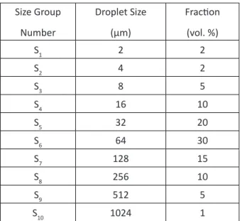
Moreover, the drop size distribution of water phase in the inlet emulsion is given in Table 3.
Table 3: Droplet size distribution of the inlet emulsion.
Size Group Number
Droplet Size (µm)
Fraction (vol. %)
S1 2 2
S2 4 2
S3 8 5
S4 16 10
S5 32 20
S6 64 30
S7 128 15
S8 256 10
S9 512 5
S10 1024 1
The inlet velocity of the emulsion is 6 mm/s regarding the inlet flow rate of the pilot electrocoalescer. The equations of the model construct a transient problem; and therefore, a proper unsteady state solution approach is applied. The time-dependent PB-CFD problem has been solved using the aforementioned equations of the model. The variations in the distribution of different size groups of the droplets have been inspected through the computational domain in progress run-time to study the droplet size growth and water separation until the steady state is reached.
RESULTS AND DISCUSSION
Numerical Results
http://jpst.ripi.ir Journal of Petroleum Science and Technology 2019, 9(4), 3-21
Figure 2: Fraction of dispersed water phase in the oil
phase.
Figure 3: Fraction of S2 size (4μm) droplets in dispersed
water content of the oil phase.
Figure 4: Fraction of S4 size (16 μm) droplets in dispersed
water content of the oil phase.
Figure 5: Fraction of S6 size (64 μm) droplets in dispersed
water content of the oil phase.
Figure 6: Fraction of S8 size (256 μm) droplets in
dispersed water content of the oil phase.
Figure 7: Fraction of S10 size (1024 μm) droplets in
Journal of Petroleum Science and Technology 2019, 9(4), 3-21 http://jpst.ripi.ir
According to Table 1, the water content of the inlet emulsion is 5.5 vol. %. At the time of 30 min, a thick region of emulsion with the water content of 4-5% has been formed above the accumulated water phase. A narrow area with the water content of 2-3% is seen above the said region. Next, a thick region of the dilute emulsion has been accumulated with the water content of about 1%. This region corresponds to the strong electric field area that seems effective in separating the water droplets. Finally, the upper region with very low water content represents the oil phase passed through the strong electric field.
The aforementioned arrangement is relatively the same at the time of 60 and 90 min, but the region of the dilute emulsion is developing towards the upside of the vessel. At t= 120 min, no significant changes were seen in the bottom half of the vessel. However, in the upper half of the vessel, the height of the dilute emulsion region has been increased upward, and instead, the thickness of the upper region has been decreased. The above-mentioned trend is continued at t= 150 min and t= 180 min. Since the profiles are not changed even up to t= 240 min, the solution is considered as the steady-state condition at the time of 180 min.
In Figure3, the profiles of S2 size (4 μm) droplets from the CFD-PB simulation at several times are displayed.
According to Table 3, the fraction of S2 size in water phase of the inlet emulsion is 2 vol%. At t= 30 min, the fraction of S2 size remained the same as inlet emulsion in the upper half of the vessel. However, the fraction of S2 size was decreased to about 1-1.5% through electrocoalescence in some area of the bottom half. The mentioned condition
is relatively the same at t= 60 min, but the area of the decreased fraction in the bottom half is limited. However, at this time, the fraction had started to decrease through electrocoalescence in the upper half of the vessel to about 1.7%. The aforesaid trend is continued at t= 90 to 180 min. A uniform profile was shaped at t= 180 min, as the fraction in the upper half of the vessel was reduced to about 1.6%, and the fraction in the bottom half was remained about 2%. Ultimately, similar results are seen in the profiles of S1 size (2 μm) droplets from the CFD-PB simulation.
http://jpst.ripi.ir Journal of Petroleum Science and Technology 2019, 9(4), 3-21
However, it was decreased to about 0-10% in some area near the wall. Moreover, consumption of S6 size droplets through electrocoalescence was extended at t= 60 min, aside from the central section. At t= 90 min, more development of the electrocoalescence reduced the fraction of S6 size droplets in a major area of the vessel to about zero, significantly in the central section. At the next times, this reduction was continued to form a uniform profile with about zero S6 size droplets, except for a limited region around the inlet nozzle. Moreover, approximate similar consequences resulted from the simulation for the profiles of S7 size (128 μm) droplets.
The profiles of S8 size (256 μm) droplets are shown in Figure 6 from the simulation results.
The fraction of S8 size droplets in water phase of the inlet flow is 10%, as presented in Table 3. At t= 30 min, the fraction of S8 size was decreased from 10% to about 9% in the major part of the vessel. However, the fraction was more reduced to about 0-4% in some area near the wall. At t= 60 min, consumption of S8 size droplets was accelerated in the entire of the vessel. At t= 90 min, more progress of the electrocoalescence reduced the fraction in a major area of the vessel to about zero, except for a narrow region of the central section. At the next times, S8 size droplets were only observed in a limited region around the inlet nozzle, which the droplets were consumed gradually by electrocoalescence. Approximate similar results were observed for the profiles of S9 size (512 μm) droplets from the simulation.
Figure 7 shows the profiles of S10 size (1024 μm) droplets resulted from the CFD-PB simulation. As presented in Table 3, the fraction of S10 size droplets
in water phase of the inlet emulsion is 1%. At t= 30 min, the fraction of S10 size remained equal to the inlet content in major part of the electrocoalescer. Though, it was increased to about 50-90% in some area near the wall. Formation of S10 size droplets through the electrocoalescence of smaller droplets was extended at t= 60 min, except for the central section. At t= 90 min, more development of the electrocoalescence increased the fraction of S10 size droplets in the entire of the vessel significantly. Increasing the fraction was accelerated at t= 120 min and continued to form a uniform profile with about 70-90% S10 size droplets. However, in a limited region around the inlet nozzle, the fraction was less, in which S10 size droplets were generated progressively from electrocoalescence of the smaller droplets.
Model Validation
As seen in Figure 2, the CFD-PB model predicts the water content in the outlet oil stream equal to 0.33% for the steady state conditions at t= 180 min. On the other hand, the result of the pilot test for the same operating condition reveals this value as 0.29%. Therefore, the predicted value of the developed PB model is validated in comparison with the experimental data. The difference between the results of the model with the actual value may be explained regarding some assumptions in the model and some probable inaccuracy of the experimental sampling and measurements.
RESULTS AND DISCCUSION
Journal of Petroleum Science and Technology 2019, 9(4), 3-21 http://jpst.ripi.ir
Figure 2 demonstrate the effect of electric field on water-oil separation performance. In the weak electric field zone between water accumulation zone and strong electric field zone (see Figure 1), the inlet w/o emulsion enters with 5.5 vol. % water content and a specified droplet size distribution (Table 3).
According to Equations 10, 12, 14, and 29, high water content, and thereby high number density of droplet size groups, enhances the probability of drops collision rates in this zone. The profile of water content shows an increasing trend from the top to the water-oil interface. On the opposite direction, the upward vertical flow of the emulsion with less water content enters the strong electric field zone. High electric field strength increases the probability of drops electrical collision rate (Equation 29) and coalescence efficiency (Equation 28). The profile of water content shows a decreasing trend from the strong electric field to the top of the vessel. Furthermore, by comparing numerical results and the experimental data, it is demonstrated that the effect of the electric field in the separation of water from the oil is predicted successfully by the EHD PB model.
The resulted profiles of some droplet size groups have been presented in Figures 3 to 7. The distributions of S2 (Figure 3) and similarly, for S1 size groups illustrate that the applied electric field intensity has a limited effect on these very small size (2-4 μm) droplets. Moreover, this result can be also explained regarding Equations 11, 14, and 29, as the collision rates and coalescence efficiency decrease significantly for the smaller droplets. The comparison between Figure 3 with Figures 4, 5, and 6 demonstrates that the removal of very small water droplets (S1-S2) through electrocoalescence
is negligible in comparison with the bigger droplets. Furthermore, the industrial applications of crude oil electrocoalescers confirm that the separation of very small size droplets is the most important challenge of this process.
The comparison of the distributions of S4 (Figure 4), S6 (Figure 5), and S8 (Figure 6) size groups with those of S10 (Figure 7) size group illustrates a direct relevance among the profiles at the same times. For example, at t= 30 min, the observed patterns for S4, S6 and S8 in Figures 4 to 6 showed specified decreased fraction regions which were coincided with the increased fraction areas of S10 size group in Figure 7. Moreover, this analogy is seen for the other displayed times similarly. These analogies show that reduction in the fraction of the small droplets finally results in an increase in the fraction of the biggest droplet. Therefore, the consequences confirm that electrocoalescence is successful for separating the water through the growth of the droplet size.
On the other hand, by comparing the results in Figures 3 to 6, some differences are observed among the variations of different drop sizes. For the very small droplets (S1-S2), the reduction of the fraction is negligible (Figure 3), while for the medium droplets (S3-S5), the decrease is more considerable, but these are not completely removed by electrocoalescence (Figure 4), whereas for the larger droplets (S6-S9), the reduction is so significant (Figure 5 and 6) as these droplets have been eliminated completely through electrocoalescence.
http://jpst.ripi.ir Journal of Petroleum Science and Technology 2019, 9(4), 3-21
vessel to about 70-90%. Additionally, in the region below the strong electric field, where the formed big droplets settle down, the most fractions of S10 size droplets become about 98%.
CONCLUSIONS
A special electrohydrodynamic PB model has been developed, which the developed model considers both hydrodynamic and electrostatic aspects in w/o emulsions. For this purpose, the hydrodynamic PB model developed by Prince and Blanch [11] was combined with the electrostatic PB model developed by Atten [26]. The overall coalescence rate of droplets is defined by the all of frequency of collision multiplied by the coalescence efficiency. Also, the model was developed so that the mechanisms of collision from the hydrodynamic sources, i.e. buoyancy, turbulence, and laminar shear are contributed in the collision frequency term beside the electric field simultaneously. Furthermore, the coalescence efficiency is calculated regarding to the govern mechanism. The modified model was implemented in a combined CFD-PBM simulation applying the same operating condition of the completed pilot test. The resulted profiles of water phase distribution demonstrated the effect of electric field on water-oil separation performance. In the zones with high water content and consequently high number densities of droplets, more progress in electrocoalescence was observed because of the enhanced probability of the collision rate. The profile of water content showed an increasing trend from the top to the water-oil interface. The probability of the electrical collision rate and coalescence efficiency was enhanced in the upward vertical flow of the emulsion inside the
strong electric field zone. Therefore, a decreasing trend was observed in water content from the strong electric field to the top. The predicted water content in the outlet oil (0.33%) was in a good agreement with the experimental data (0.29%). Moreover, the profiles of different droplet sizes illustrated that removal of the very small droplets (<4 μm) was minor, while reduction of the medium sizes (8-32 μm) was more considerable but not complete whereas elimination of the larger droplets (>64 μm) was complete. On the other hand, the largest droplet size (1024 μm) displayed a significant population growth, normally to about 90%. Therefore, the modified model assists us in predicting the internal situations of the phases and the size distribution of the droplets in crude oil electrocoalescers. Finally, the resulted data from CFD-PBM simulation are useful for designing the electric field and improving the hydraulic of the internal fluid flow.
NOMENCLATURES
b : breakage frequency, s-1B : birth rates, m-3 s-1
c : coalescence rate, s-1
D : death rates, m-3 s-1
d : distance between drop centers, m E0: electric field intensity, V m-1
F : force, N
g : gravity acceleration, m s-2
n : number density, m-3
p : the net rate of production of droplets, m-3 s-1
r : drop radius, m
s : collision cross-sectional area, m2
t : time, s u : velocity, m s-1
Journal of Petroleum Science and Technology 2019, 9(4), 3-21 http://jpst.ripi.ir
Greeks Letters
β : probability density function γ : average shear rate, s-1
є : energy dissipation rate per mass, m2 s-2
ε : relative permittivity η : coalescence efficiency θ : collision frequency, s-1
ν : dynamic viscosity, Pa. s ρ : Density, kg m-3
σ : interfacial tension, N m-1
τ : contact time, s Φ : volume fraction
ψ : electric field skew angle, degree Subscripts / Superscripts
B : buoyant C : coalescence E : electrical o : oil
r : radial direction S : laminar shear T : turbulent
θ : tangential direction w : water
REFERENCES
1. Mohammadi M., Shahhosseini S., and Bayat M., “Direct Numerical Simulation of Water Droplet Coalescence in the Oil,” International Journal of Heat and Fluid Flow, 2012, 36, 58-71.
2. Lee C. M., Sams G. W., and Wagner J. P., “Power Consumption Measurements for Ac and Pulsed dc for Electrostatic Coalescence of Water-in-oil Emulsions,” Journal of Electrostatics, 2001, 53(1), 1-24.
3. Guo C. and He L., “Coalescence Behaviour of Two Large Water-drops in Viscous Oil under a DC Electric Field,” Journal of Electrostatics,
2014, 72(6), 470-476.
4. Mohammadi M., Shahhosseini S., and Bayat M., “Numerical Prediction of the Electrical Waveform Effect on Electrocoalescence Kinetic,” Chemical Engineering Research and Design,
2013, 91(5), 904-918.
5. Mohammadi M., Shahhosseini S., and Bayat M., “Numerical Study of Collision and Coalescence of Water Droplets in an Electric Field,” Chemical Engineering and Technology,
2014, 37(1), 27-35.
6. Mohammadi M., Shahhosseini S., and Bayat M., “Electrocoalescence of Binary Water Droplets Falling in Oil: Experimental Study,” Chemical Engineering Research and Design,
2014, 92, 2694-2704.
7. Soni P., Juvekar V. A., and Naik V. M., “Investigation on Dynamics of Double Emulsion Droplet in a Uniform Electric Field,” Journal of Electrostatics, 2013, 71(3), 471-477.
8. Mohammadi M., “Numerical and Experimental Study on Electric Field Driven Coalescence of Binary Falling Droplets in Oil,” Separation and Purification Technology, 2017, 176, 262-276. 9. Verdoold S., and Marijnissen J. C. M., “Modeling
a Bipolar-coagulation Reactor Using Coupled Population Balances,” Journal of Electrostatics,
2011, 69(3), 240-254.
10. Coulaloglou C. A., and Tavlarides L. L., “Description of Interaction Processes in Agitated Liquid-liquid Dispersions,” Chemical Engineering Science, 1977, 32(11), 1289-1297. 11. Prince M. J., and Blanch H. W., “Bubble
Coalescence and Break-up in Air-sparged Bubble Columns,” AIChE Journal, 1990, 36(10), 1485-1499.
12. Tsouris C., Tavlarides L. L., “Breakage and Coalescence Models for Drops in Turbulent Dispersions,”AIChE Journal, 1994, 40(3), 395-406.
http://jpst.ripi.ir Journal of Petroleum Science and Technology 2019, 9(4), 3-21
14. Guo C., He L., and Xin Y., “Deformation and Breakup of Aqueous Drops in Viscous Oil under a Uniform AC Electric Field,” Journal of Electrostatics, 2015, 77, 27-34.
15. He L., Huang X., Luo X., and Yan H., “Numerical Study on Transient Response of Droplet Deformation in a Steady Electric Field,” Journal of Electrostatics, 2016, 82, 29-37.
16. Abbasi M. S., Song R., Kim J., and Lee J., “Electro-hydrodynamic Behavior and Interface Instability of Double Emulsion Droplets under High Electric Field,” Journal of Electrostatics,
2017, 85, 11-22.
17. Drumm C., Attarakih M. M., and Bart H. J., “Coupling of CFD with DPBM for an RDC Extractor,” Chemical Engineering Science, 2009, 64(4), 721-732.
18. Kamp J. and Kraume M., “Coalescence Efficiency Model Including Electrostatic Interactions in Liquid/liquid Dispersions,” Chemical Engineering Science, 2015, 126, 132–142.
19. Israelachvili J. N., “Ntermolecular and Surface Forces,” (2nd ed.) Academic Press: London, UK,
1991.
20. Derjaguin B. V., Churaev N. V., and Muller V. M., “Surface Forces,” Consultants Bureau: New York, USA, 1987.
21. Barega E. W., Zondervan E., and De Haan A. B., “A Combined Lossy Capacitor Population Balance Model (LCPBM) for Calculating the Influence of Frequency on Electric Field Enhanced Coalescence in a Static-mixer Settler Setup,” Chemical Engineering Science, 2013, 104, 727-741. 22. Meidanshahi V., Jahanmiri A., and Rahimpour
M. R., “Modeling and Optimization of Two Stage AC Electrostatic Desalter,” Separation
Science and Technology, 2012, 47, 30–42. 23. Aryafard E., Farsi M., and Rahimpour M. R.,
“Modeling and Simulation of Crude Oil Desalting in an Industrial Plant Considering Mixing Valve and Electrostatic Drum,” Chemical Engineering and Processing, 2015, 95, 383–389.
24. Aryafard E., Farsi M., Rahimpour M. R., and Raeissi S., “Modeling Electrostatic Separation for Dehydration and Desalination of Crude Oil in an Industrial Two-stage Desalting Plant,” Journal of the Taiwan Institute of Chemical Engineers, 2016, 58, 141–147.
25. Manga M., and Stone H., “Collective Hydrodynamics of Deformable Drops and Bubbles in Dilute Low Reynolds Number Suspensions,” Journal of Fluid Mechanics, 1995, 300, 231-263.
26. Atten P., “Electrocoalescence of water droplets in an insulating liquid,” Journal of Electrostatics,
1993, 30, 259-270.
27. Ramkrishna D., “Population Balances: Theory and Applications to Particulate Systems in Engineering,” Academic Press: San Diego, USA, 2000.
28. Kumar S., and Ramkrishna D., “On the Solution of Population Balance Equations by Discretization-I. A Fixed Pivot Technique,” Chemical Engineering Science, 1996, 51(8), 1311-1332.
29. Kumar J., Peglow M., Warnecke G., and Heinrich S., “Improved Accuracy and Convergence of Discretized Population Balance for Aggregation: The Cell Average Technique,” Chemical Engineering Science, 2006, 61(10), 3327-3342.