User Guide IM/AX4PH Rev. O
AX416, AX436, AX460, AX466 & AX468
The Company
We are an established world force in the design and manufacture of measurement products for industrial process control, flow measurement, gas and liquid analysis and environmental applications.
As a part of ABB, a world leader in process automation technology, we offer customers application expertise, service and support worldwide.
We are committed to teamwork, high quality manufacturing, advanced technology and unrivalled service and support.
The quality, accuracy and performance of the Company’s products result from over 100 years experience, combined with a continuous program of innovative design and development to incorporate the latest technology.
EN ISO 9001:2000
Cert. No. Q 05907 EN 29001 (ISO 9001)
Lenno, Italy – Cert. No. 9/90A Stonehouse, U.K.
Electrical Safety
This equipment complies with the requirements of CEI/IEC 61010-1:2001-2 'Safety Requirements for Electrical Equipment for Measurement, Control and Laboratory Use'. If the equipment is used in a manner NOT specified by the Company, the protection provided by the equipment may be impaired.
Symbols
One or more of the following symbols may appear on the equipment labelling:
Warning – Refer to the manual for instructions Direct current supply only
Caution – Risk of electric shock Alternating current supply only
Protective earth (ground) terminal Both direct and alternating current supply
Earth (ground) terminal The equipment is protected
through double insulation
Information in this manual is intended only to assist our customers in the efficient operation of our equipment. Use of this manual for any other purpose is specifically prohibited and its contents are not to be reproduced in full or part without prior approval of the Technical Publications Department.
Health and Safety
To ensure that our products are safe and without risk to health, the following points must be noted: 1. The relevant sections of these instructions must be read carefully before proceeding. 2. Warning labels on containers and packages must be observed.
3. Installation, operation, maintenance and servicing must only be carried out by suitably trained personnel and in accordance with the information given.
4. Normal safety precautions must be taken to avoid the possibility of an accident occurring when operating in conditions of high pressure and/or temperature.
5. Chemicals must be stored away from heat, protected from temperature extremes and powders kept dry. Normal safe handling procedures must be used.
6. When disposing of chemicals ensure that no two chemicals are mixed.
Safety advice concerning the use of the equipment described in this manual or any relevant hazard data sheets (where applicable) may be obtained from the Company address on the back cover, together with servicing and spares information.
Single and dual input analyzers for pH/Redox (ORP)
AX416, AX436, AX460, AX466 & AX468 Contents
Contents
1 Introduction ... 2
1.1 System Description ... 2
1.2 PID Control ... 2
1.3 AX400 Series Analyzer Options ... 2
2 Operation ... 3
2.1 Powering Up the Analyzer ... 3
2.2 Displays and Controls ... 3
2.2.1 Membrane Key Functions ... 3
2.3 Operating Page ... 6
2.3.1 Single Input pH ... 6
2.3.2 Dual Input pH ... 7
2.3.3 Single Input Redox (ORP) ... 8
2.3.4 Dual Input Redox (ORP) ... 9
2.3.5 Dual Input pH and Redox (ORP) ... 10
2.3.6 Wash Function ... 11
3 Operator Views ... 12
3.1 View Set Points ... 12
3.2 View Outputs ... 14 3.3 View Hardware ... 14 3.4 View Software ... 15 3.5 View Logbook ... 16 3.6 View Clock ... 18 4 Setup ... 19 4.1 Sensor Calibration ... 19
4.1.1 Set Buffer Type (pH Only) ... 19
4.1.2 Set Up User Defined Buffers (pH Only) ... 21
4.1.3 Adjust Offset (Redox/ORP Only) ... 22
4.1.4 Automatic, Single- and Two-Point Calibration (pH Only) ... 23
4.1.5 Manual, Single- and Two-Point Calibration (pH Only) ... 25
4.1.6 Grab Calibration (pH Only) ... 27
5 Programming ... 28 5.1 Security Code ... 28 5.2 Configure Display ... 29 5.3 Configure Sensors ... 30 5.4 Configure Diagnostics ... 33 5.5 Configure Alarms ... 34
5.5.1 Wash Cycle Configuration (Applicable Only to Alarm 3) ... 36
5.6 Configure Outputs ... 38
5.7 Configure Clock ... 40
5.8 Configure Security ... 41
5.9 Configure Logbook ... 41
5.10 Test Outputs and Maintenance ... 42
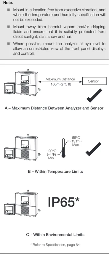
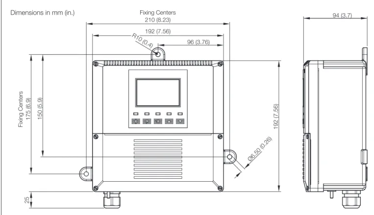
6 Installation ... 44 6.1 Siting Requirements ... 44 6.2 Mounting ... 45 6.2.1 Wall-/Pipe-mount Analyzers ... 45 6.2.2 Panel-mount Analyzers ... 46 6.3 Connections, General ... 47
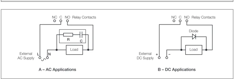
6.3.1 Relay Contact Protection and Interference Suppression ... 48
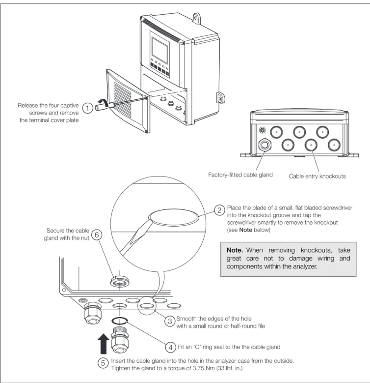
6.3.2 Cable Entry Knockouts, Wall-/Pipe-mount Analyzer ... 49
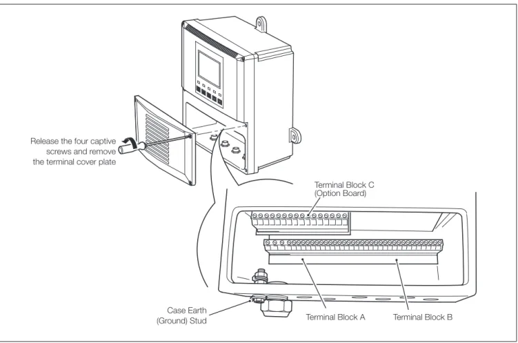
6.4 Wall-/Pipe-mount Analyzer Connections ... 50
6.4.1 Access to Terminals ... 50
6.4.2 Connections ... 51
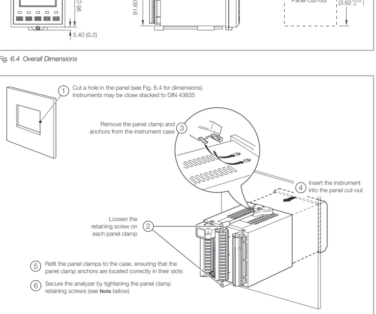
6.5 Panel-mount Analyzer Connections ... 52
6.5.1 Access to Terminals ... 52
6.5.2 Connections ... 53
6.6 pH Sensor Systems Connections ... 54
6.6.1 Standard ph Systems Connection – 2867, AP100, AP300, 7650/60, TB5, Non-ABB ... 54
6.6.2 Differential ph Systems Connections – Capable of Providing Sensor Diagnostics (AP200, TBX5) ... 55
7 Calibration ... 56
7.1 Equipment Required ... 56
7.2 Preparation ... 56
7.3 Factory Settings ... 57
8 Simple Fault Finding ... 62
8.1 Error Messages ... 62
8.2 Calibration Fail Message or No Response to pH/Redox Changes ... 62
8.3 Checking the Temperature Input ... 63
9 Specification ... 64
Single and dual input analyzers for pH/Redox (ORP)
AX416, AX436, AX460, AX466 & AX468 1 Introduction
1 Introduction
1.1 System Description
The AX460 single input and AX466 dual input pH/Redox (ORP) analyzers and associated electrode systems have been designed for continuous monitoring and control of pH and Redox (ORP). The electrode system can be standardized to the analyzer using the built-in calibration facility and a single point buffering facility provides easy re-calibration after initial standardization.
The analyzer is available in wall-/pipe-mount or panel-mount versions with either one or two programmable, pH or Redox (ORP) input channels, each with its own associated temperature input channel. When making temperature compensated measurements, the sample temperature is sensed by a resistance thermometer (Pt100, Pt1000 or Balco 3K) mounted in the electrode system.
The analyzer can be configured for, and connected to, either a standard pH input (single, high impedance input >1013 ) or
differential pH input (dual, high impedance inputs, both >1013).
Differential pH input is designed for use with pH electrode systems that incorporate a solution earth (ground) rod. The measuring electrode and reference electrode signals are measured separately using two, high impedance amplifiers and compared with the solution earth (ground) potential. The difference between the results is the value used for the pH measurement.
All models incorporate a wash facility for system cleaning; the Alarm 3 relay can be configured to control the wash system either automatically or manually. The relay can be programmed to deliver either a continuous or pulsed signal to control an external power supply to a solenoid or pump and the frequency, duration and recovery time for the wash cycle are also programmable. During a wash cycle, the analog output value is held in its pre-cycle condition.
Analyzer operation and programming are performed using five tactile membrane keys on the front panel. Programmed functions are protected from unauthorized alteration by a four-digit security code.
1.2 PID Control
The AX460 single input pH analyzer incorporates Proportional Integral Derivative (PID) control as standard. Refer to the
PID Control Supplementary User Guide, IM/AX4PID for a full description and instructions on how to configure and operate PID control.
1.3 AX400 Series Analyzer Options
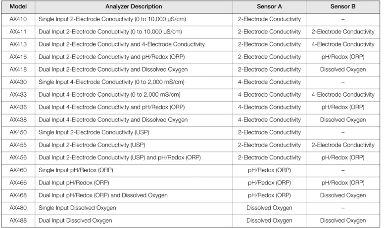
Table 1.1 shows the range of configurations that are possible for the AX400 Series analyzers. The analyzer detects the type of input board fitted for each input automatically and displays only the operating and programming frames applicable to that input board type. If no input board is fitted for a second input (Sensor B), Sensor B frames are not displayed.
Model Analyzer Description Sensor A Sensor B
AX410 Single Input 2-Electrode Conductivity (0 to 10,000 µS/cm) 2-Electrode Conductivity –
AX411 Dual Input 2-Electrode Conductivity (0 to 10,000 µS/cm) 2-Electrode Conductivity 2-Electrode Conductivity AX413 Dual Input 2-Electrode Conductivity and 4-Electrode Conductivity 2-Electrode Conductivity 4-Electrode Conductivity AX416 Dual Input 2-Electrode Conductivity and pH/Redox (ORP) 2-Electrode Conductivity pH/Redox (ORP) AX418 Dual Input 2-Electrode Conductivity and Dissolved Oxygen 2-Electrode Conductivity Dissolved Oxygen AX430 Single Input 4-Electrode Conductivity (0 to 2,000 mS/cm) 4-Electrode Conductivity –
AX433 Dual Input 4-Electrode Conductivity (0 to 2,000 mS/cm) 4-Electrode Conductivity 4-Electrode Conductivity AX436 Dual Input 4-Electrode Conductivity and pH/Redox (ORP) 4-Electrode Conductivity pH/Redox (ORP) AX438 Dual Input 4-Electrode Conductivity and Dissolved Oxygen 4-Electrode Conductivity Dissolved Oxygen AX450 Single Input 2-Electrode Conductivity (USP) 2-Electrode Conductivity –
AX455 Dual Input 2-Electrode Conductivity (USP) 2-Electrode Conductivity 2-Electrode Conductivity AX456 Dual Input 2-Electrode Conductivity (USP) and pH/Redox (ORP) 2-Electrode Conductivity pH/Redox (ORP)
AX460 Single Input pH/Redox (ORP) pH/Redox (ORP) –
AX466 Dual Input pH/Redox (ORP) pH/Redox (ORP) pH/Redox (ORP) AX468 Dual Input pH/Redox (ORP) and Dissolved Oxygen pH/Redox (ORP) Dissolved Oxygen
AX480 Single Input Dissolved Oxygen Dissolved Oxygen –
AX488 Dual Input Dissolved Oxygen Dissolved Oxygen Dissolved Oxygen
Single and dual input analyzers for pH/Redox (ORP)
AX416, AX436, AX460, AX466 & AX468 2 Operation
2 Operation
2.1 Powering Up the Analyzer
1. Ensure the input sensors are connected correctly. 2. Switch on the power supply to the analyzer. A start-up
screen is displayed while internal checks are performed, then the Operating Page (Section 2.3) is displayed as the pH or Redox (ORP) monitoring operation starts.
2.2 Displays and Controls
The display comprises two rows of 41/2 digit, 7-segment digital
displays, that show the actual values of the measured parameters and alarm set points, and a 6-character dot matrix display showing the associated units. The lower display line is a 16-character dot matrix display showing operating and programming information.
2.2.1 Membrane Key Functions
Warning. Ensure all connections are made correctly,
especially to the earth stud – see Section 6.3, page 47.
Fig. 2.1 Location of Controls and Displays
0.00
Monitoring pH0.00
Alarm LEDs Display Lines Lower Display Line Membrane Keys pH Units Menu Key Sidescroll Key Downscroll Key Up Key Down Key pHFig. 2.2 Membrane Key Functions
B Advancing to Next Page
C Moving Between Frames
D Adjusting and Storing a Parameter Value
E Selecting and Storing a Parameter Choice A Moving Between Menus
For majority of Frames Frame 1 Frame 2 Frame 3 Frame 4 Page 1 Frame 1 Frame 2 Frame 3 Page 2 Advance to next page or Frame 1 Frame 2 Frame 3 Page X Frame 4 Advance to next Frame New value is stored automatically
Parameter Value Adjust
Parameter X Y Z Select New value is automatically stored Menu 1 Menu 2 Advance to next menu
Single and dual input analyzers for pH/Redox (ORP)
AX416, AX436, AX460, AX466 & AX468 2 Operation
Key
VIEW SETPOINTS VIEW OUTPUTS VIEW HARDWARE VIEW SOFTWARE A1: Setpoint Analog Output 1 Sensor A Module AX400/2000 Issue A2: Setpoint Analog Output 2 Sensor B Module
A3: Setpoint Analog Output 3 Option Board A4: Setpoint Analog Output 4
A5: Setpoint
SECURITY CODE
CONFIG. DISPLAY Set Language Set Temp. Units Set Backlight LED Backlight Temp. Units
English
Use the Sidescroll Key to scroll through the Pages within each Menu
To CONFIG. ALARMS (see Fig. 2.4)
Use the Downscroll Key to scroll through
the Frames within each Page OPERATING PAGE
Section 2.3, Page 6 Section 3.1, Page 12 Section 3.2, Page 14 Section 3.3, Page 14 Section 3.4, Page 15 Section 3.5, Page 16
Section 5.1, Page 28 Section 5.2, Page 29 Section 3.6, Page 18 Alarms Errors Power Cals VIEW LOGBOOK
Dual input analyzer only
VIEW CLOCK Date 01:01:03 Time 12:00
*
Displayed only if Probe Type is set to Redox or ORPCONFIG.DIAGS Section 5.4, Page 33 Config. Sensor A A: pH Glass A: Ref. Checking A: Ref. Alarm
Config. Sensor A Config. Sensor B B: pH Glass B: Ref. Checking B: Ref. Alarm Use the Menu Key
to scroll through the Menus CONFIG.SENSORS B: Probe Type B: Diff. Input B: Electrode B: Temp. Comp B: Temp. Sensor B: Preset Temp. B: Sample Comp. B: Sample Coeff. Section 5.3, Page 30
B: Set Min Slope Config. Sensor B Config. Sensor A A: Probe Type A: Diff. Input A: Temp. Comp A: Temp. Sensor A: Preset Temp. A: Sample Comp. A: Sample Coeff. A: Set Min Slope A: Electrode
A: Enable Cals B: Enable Cals
*
*
SENSOR CAL. Cal. User Code Sensor Cal. A A: Buffer Method A: Immerse Buf.1 A: Cal. Buffer 1 A: Immerse Buf.2 A: Cal. Buffer 2 A: Calibration Section 4.1, Page 19
Set Auto Buffers Buffer Type Set Buffer 1 Set Buffer 2
A: Slope & Check
Sensor Cal. B B: Buffer Method B: Immerse Buf.1 B: Cal. Buffer 1 B: Immerse Buf.2 B: Cal. Buffer 2 B: Calibration B: Slope & Check A: Enter Point 1 A: Enter Point 2 B: Enter Point 1 A: Enter Point 5 A: Enter Point 4 A: Enter Point 3 B: Enter Point 2 B: Enter Point 5 B: Enter Point 4 B: Enter Point 3 #### 100% #### #### 100% #### #### 100% #### #### 100% ####
Note. Sensor calibration parameters shown above are for Automatic, 2-point calibration only. For other calibration options, refer to Section 4.1.
Available only if option board fitted and
Single and dual input analyzers for pH/Redox (ORP)
AX416, AX436, AX460, AX466 & AX468 2 Operation
CONFIG.ALARMS Config. Alarm 1 A1: Type A1: Assign A1: Failsafe A1: Action A1: Setpoint A1: Hysteresis A1: Delay Config. Alarm 2 A2: Type A2: Assign A2: Failsafe A2: Action A2: Setpoint A2: Hysteresis A2: Delay A3: Assign A3: Failsafe A3: Action A3: Setpoint A3: Hysteresis A3: Delay To FACTORY SETTINGS (see Section 7.3, Page 57)
Config. Alarm 3 A3: Type
Use the Sidescroll Key to scroll through the Pages within each Menu
Section 5.5, Page 34
Use the Downscroll Key to scroll through
the Frames within each Page
Config. Alarm 4 A4: Type A4: Assign A4: Failsafe A4: Action A4: Setpoint A4: Hysteresis A4: Delay Config. Alarm 5 A5: Type A5: Assign A5: Failsafe A5: Action A5: Setpoint A5: Hysteresis A5: Delay Wash Frequency Wash Duration Recovery Period Wash Mode
*
*
Applicable only to Alarm 3 CONFIG.LOGBOOK Section 5.9, Page 41 Logbook CONFIG.SECURITY Alter Sec.CodeAlter Cal.Code Section 5.8, Page 41
CONFIG.CLOCK Set Clock? Format dd/mm/yy Date 01:01:02 Time 12:00 Press To Abort Press To Set Section 5.7, Page 40 Use the Menu Key
to scroll through the Menus
CONFIG.OUTPUTS Config. Output 1 AO1: Assign AO1: Range AO1: Span Value AO1: Zero Value AO1: Default AO1: Default Val
Config. Output 2 AO2: Assign AO2: Range AO2: Span Value AO2: Zero Value AO2: Default AO2: Default Val
Config. Output 3 AO3: Assign AO3: Range AO3: Span Value AO3: Zero Value AO3: Default AO3: Default Val Section 5.6, Page 38
Config. Output 4 AO4: Assign AO4: Range AO4: Span Value AO4: Zero Value AO4: Default AO4: Default Val
Single Input Analyzer Only see Supplementary Manual PID Control (IM/AX4PID) CONFIG. CONTROL
TEST/MAINTENANCE Test Outputs Test Output 1 Test Output 2 Maintenance Hold Outputs Test Output 3 Test Output 4 Section 5.10, Page 42 Load/Save Config Factory Config. User Config. Press To Abort Press To Set
CONFIG.SERIAL Displayed only if option board fitted see Supplementary Manual Profibusand® Datalink Description (IM/AX4/PBS) serial communications feature enabled (Section 7.3)
Automatic Time
Key
Available only if option board fitted and
Single and dual input analyzers for pH/Redox (ORP)
AX416, AX436, AX460, AX466 & AX468 2 Operation
2.3 Operating Page 2.3.1 Single Input pH Measured Values pH. Temperature. Measured Millivolts Millivolts.
% Slope and pH Check Value % slope value.
A value between the programmed minimum % slope value (see Set Min Slope – see Section 5.3, page 30) and 105% is displayed. If the value is outside these limits, check the electrode system.
pH check value (zero point).
Displayed as an additional indication of pH electrode system condition; 7 pH is the optimum value for glass electrodes and 0 ph for Antimony electrodes.
See Section 3.1, page 12. See Section 4.1, page 19.
A3: Type set to Wash (Section 5.5) – see Section 2.3.6, page 11.
A3: Type not set to Wash (Section 5.5) – return to top of page.
Monitoring pH
7.00
pH24.4
Deg.C Monitoring pH Millivolts404
mVA: Slope & Check
100.0
%7.00
pHVIEW SETPOINTS SENSOR CAL. Wash Function
Single and dual input analyzers for pH/Redox (ORP)
AX416, AX436, AX460, AX466 & AX468 2 Operation
2.3.2 Dual Input pH Measured pH Sensor A. Sensor B. Measured Temperature Sensor A. Sensor B. Measured Millivolts Sensor A. Sensor B.
% Slope and pH Check Value – Sensor A % slope value.
A value between the programmed minimum % slope value (see Set Min Slope – see Section 5.3, page 30) and 105 % is displayed. If the value is outside these limits, check the electrode system.
pH check value (zero point).
Displayed as an additional indication of pH electrode system condition; 7 ph being the optimum value for glass electrodes and 0 ph for Antimony electrodes.
% Slope and pH Check Value – Sensor B % slope value.
See Sensor A above. pH check value (zero point).
See Section 3.1, page 12. See Section 4.1, page 19.
A3: Type set to Wash (Section 5.5) – see Section 2.3.6, page 11.
A3: Type not set to Wash (Section 5.5) – return to top of page.
Monitoring pH
7.00
pH7.00
pH Temperature25.6
Deg.C Millivolts404
mVA: Slope & Check
100.0
%7.00
pH24.4
Deg.C-256
mVB: Slope & Check % pH
100.0
7.00
Monitoring pH VIEW SETPOINTS SENSOR CAL. Wash FunctionSingle and dual input analyzers for pH/Redox (ORP)
AX416, AX436, AX460, AX466 & AX468 2 Operation
2.3.3 Single Input Redox (ORP)
Measured Values Millivolts.
Temperature.
Offset – Sensor A
Displays the offset value for the sensor set in A: Adjust Offset – see Section 4.1.3, page 22.
See Section 3.1, page 12. See Section 4.1, page 19.
A3: Type set to Wash (Section 5.5) – see Section 2.3.6, page 11.
A3: Type not set to Wash (Section 5.5) – return to top of page.
Redox (ORP)
404
mV25.6
Deg.C A: mV Offset0
mV Redox (ORP) VIEW SETPOINTS SENSOR CAL. Wash FunctionSingle and dual input analyzers for pH/Redox (ORP)
AX416, AX436, AX460, AX466 & AX468 2 Operation
2.3.4 Dual Input Redox (ORP)
Measured Millivolts Sensor A.
Sensor B.
Note. If Probe Type for both Sensor A and Sensor B is set to ORP (Section 5.3), the lower display line shows Dual ORP.
Sample Temperature Sensor A.
Sensor B.
Note. The measured temperature is displayed only if Temp. Sensor is not set to None – see Section 5.3, page 30.
Offset – Sensor A
Displays the offset value for Sensor A set in A: Adjust Offset – see Section 4.1.3, page 22.
Offset – Sensor B
Displays the offset value for Sensor B set in B: Adjust Offset – see Section 4.1.3, page 22.
See Section 3.1, page 12. See Section 4.1, page 19.
A3: Type set to Wash (Section 5.5) – see Section 2.3.6, page 11.
A3: Type not set to Wash (Section 5.5) – return to top of page.
Dual Redox
404
mV-256
Temperature25.6
Deg.C24.4
Deg.C mV A: mV Offset0
mV B: mV Offset0
mV Dual Redox VIEW SETPOINTS SENSOR CAL. Wash FunctionSingle and dual input analyzers for pH/Redox (ORP)
AX416, AX436, AX460, AX466 & AX468 2 Operation
2.3.5 Dual Input pH and Redox (ORP)
Measured pH and Millivolts Sensor A.
Sensor B.
Note. The Probe Type for Sensors A and B can be set to any combination of pH, Redox
or ORP – see Section 5.3, page 30. The display indications change depending on
Probe Type settings, e.g. if Sensor A is set to Redox and Sensor B to pH, the lower display shows Redox (ORP)/pH.
Measured Temperature Sensor A.
Sensor B.
Note. The measured temperature is displayed only if Temp. Sensor is not set to None – see Section 5.3, page 30.
Measured Millivolts Sensor A.
Sensor B.
Offset – Sensor B
Displays the offset value for Sensor B set in B: Adjust Offset – see Section 4.1.3, page 22.
% Slope and pH Check Value – Sensor A % slope value.
A value between the programmed minimum % slope value (see Set Min Slope – Section 5.3) and 105 % is displayed. If the value is outside these limits, check the electrode system.
pH check value (zero value).
Displayed as an additional indication of pH electrode system condition; 7 ph is the optimum value for glass electrodes and 0 ph for Antimony electrodes.
See Section 3.1, page 12. See Section 4.1, page 19.
A3: Type set to Wash (Section 5.5) – see Section 2.3.6, page 11.
A3: Type not set to Wash (Section 5.5) – return to top of page.
pH/Redox (ORP)
7.00
pH-256
mV Temperature25.6
Deg.C Millivolts404
mVA: Slope & Check
100.0
%7.00
pH24.4
Deg.C-256
mV B: mV Offset0
mV pH/Redox (ORP) VIEW SETPOINTS SENSOR CAL. Wash FunctionSingle and dual input analyzers for pH/Redox (ORP)
AX416, AX436, AX460, AX466 & AX468 2 Operation
2.3.6 Wash Function
Note. The Wash function is available only if A3: Type is set to Wash – see Section 5.5, page 34.
Wash Function Off On Manual – – –
Wash function off. Lower display line of Operating Page shows WASH
INHIBITED.
Wash function controlled automatically. Lower display line of Operating Page shows WASH IN PROGRESS.
Enables wash function to be initiated manually – see below. Note. Set Wash Function to Off before removing the sensor from the process. See Section 3.1, page 12.
Probe Type set to pH (for either sensor if dual input analyzer) – see Section 5.3, page 30.
See Section 4.1, page 19.
Probe Type set to Redox or ORP (for both sensors in any combination if dual input analyzer) – see Section 5.3, page 30.
Enable Cals set to Yes (Section 5.3) – see Section 4.1, page 19.
Alter Sec. Code not set to zero (Section 5.8) – see Section 5.1, page 28.
Alter Sec. Code set to zero (Section 5.8) – see Section 5.2, page 29.
Wash Function set to Manual – see below.
Wash Function not set to Manual. The display returns to the top of the Operating Page.
Press to Wash (Manual Wash only)
Press to Wash and Press to Abort are shown alternately on the lower display line.
Press the key to initiate the wash cycle. The display returns to the top of the
Operating Page and the lower display line shows WASH IN PROGRESS until the wash cycle is completed. The Wash Function selection reverts to the one that was set before
Manual was selected.
Press the key to abort the wash cycle. The display returns to the top of the
Operating Page. VIEW SETPOINTS SENSOR CAL. Wash Function
---Manual On Off ---Press To Wash Press To Abort SENSOR CAL. Security Code CONFIG. DISPLAY Press To Wash Monitoring pH WASH IN PROGRESS Monitoring pH Redox (ORP) Dual Redox pH/Redox (ORP) Redox (ORP) Dual Redox pH/Redox (ORP)Single and dual input analyzers for pH/Redox (ORP)
AX416, AX436, AX460, AX466 & AX468 3 Operator Views
3 Operator Views
3.1 View Set Points
Note. The parameter names and units of measurement displayed in the View Set Points page depend on the Probe Type settings for Sensors A and B – see Section 5.3, page 30. Those shown below are given as examples only.
View Set Points
This page shows alarm set points. The value of each of the set points is shown, together with the name of the parameter it is assigned to.
Alarm assignments, set point values and relay/LED actions are programmable – see Section 5.4, page 33.
Sensor A (pH), Alarm 1 Set Point
Sensor A (Temperature), Alarm 2 Set Point
Sensor B (pH), Alarm 3 Set Point – Dual input analyzers only
Sensor B (Temperature), Alarm 4 Set Point – Dual input analyzers only
Note. Alarm 4 available only if option board fitted and analog features enabled – see Section 7.3, page 57.
Alarm 5 Set Point
Note. Alarm 5 available only if option board fitted and analog features enabled – see Section 7.3, page 57.
See Section 3.2, page 14.
See Note on next page.
8.30
pH A1: Setpoint Sen.A Temp.A VIEW SETPOINTS---35.0
Deg.C A2: Setpoint Sen.B6.80
A3: Setpoint Temp.B55.0
Deg.C A4: Setpoint---
Off A5: Setpoint VIEW OUTPUTS SENSOR CAL. Security Code CONFIG. DISPLAY VIEW SETPOINTS pHSingle and dual input analyzers for pH/Redox (ORP)
AX416, AX436, AX460, AX466 & AX468 3 Operator Views
Note. The menu displayed when pressing the key from the Operator View pages depends on analyzer configuration, i.e.: Single Input Analyzers
Probe Type set to pH
or
Probe Type set to Redox or ORPandEnable Cals set to Yes (Section 5.3) – see Section 4.1, page 19.
Probe Type set to Redox or ORPandEnable Cals set to No (Section 5.3) andAlter Sec. Code not set to zero (Section 5.8) – see Section 5.1, page 28.
Probe Type set to Redox or ORPandEnable Cals set to No (Section 5.3) andAlter Sec. Code set to zero (Section 5.8) – see Section 5.2, page 29.
Dual Input Analyzers
Probe Type for either sensor set to pH or
Probe Type for both sensors set to Redox or ORPandEnable Cals for either sensor set to Yes (Section 5.3) – see Section 4.1, page 19.
Probe Type for both sensors set to Redox or ORPandEnable Cals for both sensors set to No (Section 5.3) and
Alter Sec. Code not set to zero (Section 5.8) – see Section 5.1, page 28.
Probe Type for both sensors set to Redox or ORPandEnable Cals for both sensors set to No (Section 5.3) and
Alter Sec. Code set to zero (Section 5.8) – see Section 5.2, page 29.
SENSOR CAL. Security Code CONFIG. DISPLAY SENSOR CAL. Security Code CONFIG. DISPLAY
Single and dual input analyzers for pH/Redox (ORP)
AX416, AX436, AX460, AX466 & AX468 3 Operator Views
3.2 View Outputs
3.3 View Hardware
Theoretical Analog Output
There are up to four analog outputs, each showing information for one sensor. Note. Analog outputs 3 and 4 available only if option board fitted and analog features enabled – see Section 7.3, page 57.
Live current output value being retransmitted.
Current output shown as a percentage of full scale for the output range set in CONFIG. OUPUTS – see Section 5.6, page 38.
See Section 3.3, below.
See Note on Page 13.
Advance to analog output 2 (and outputs 3 and 4 if option board fitted and analog features enabled – see Section 7.3, page 57).
50.0
% Analog Output 112.00
mA VIEW OUTPUTS ---VIEW HARDWARE SENSOR CAL. Security Code CONFIG. DISPLAY Analog Output 2 Sensor A ModuleShows the type of input board fitted to the analyzer for the Sensor A input.
Sensor B Module – Dual input analyzers only
Shows the type of input board fitted to the analyzer for the Sensor B input.
Option Board
Note. Displayed only if the option board is fitted.
Displays the optional features enabled in the Factory Settings page – see Section 7.3, page 57.
See Section 3.4, page 15.
See Note on Page 13.
pH pH
---Sensor A Module VIEW HARDWARE ---Option Board ---Sensor B Module---
Pb Dp Analog VIEW SOFTWARE SENSOR CAL. Security Code CONFIG. DISPLAY VIEW HARDWARESingle and dual input analyzers for pH/Redox (ORP)
AX416, AX436, AX460, AX466 & AX468 3 Operator Views
3.4 View Software
Issue
Shows the version number of the operating software.
Option board fitted and analog features enabled (Section 7.3) andLogbook set to On
(Section 5.9) – see Section 3.5, page 16.
Operating Page (option board not fitted) – see Section 2.3, page 6.
See Note on Page 13.
1.00
AX400/2000 Issue VIEW SOFTWARE ---VIEW LOGBOOK SENSOR CAL. Security Code CONFIG. DISPLAY VIEW SOFTWARE Monitoring pH Redox (ORP) Dual Redox pH/Redox (ORP)Single and dual input analyzers for pH/Redox (ORP)
AX416, AX436, AX460, AX466 & AX468 3 Operator Views
3.5 View Logbook
Note. The View Logbook function is available only if the option board is fitted and analog features enabled (see Section 7.3, page 57) andLogbook is set to On (see Section 5.9, page 41).
The logbook stores data entries for alarm events, sensor errors, power failures and pH calibration information.
View Logbook
Use the and keys to access the Alarms logbook.
Note. If no entries are stored in the Alarms logbook, the display shows No More
Entries.
Alarms
The Alarms logbook contains up to 10 entries (entry 1 is the most recent), each comprising an alarm number, alarm state (On or Off) and the date/time of the occurrence.
Option board fitted and analog features enabled (Section 7.3) – see Section 3.6, page 18.
See Note on Page 13.
Advance to entries 2 to 10.
Note. If no more entries are stored, the display shows No More Entries.
View Logbook
Use the and keys to access the Errors logbook.
Note. If no entries are stored in the Errors logbook, the display shows No More Entries.
Errors
The Errors logbook contains up to 5 entries (entry 1 is the most recent), each comprising the sensor letter, error number and the date/time of the occurrence.
Option board fitted and analog features enabled (Section 7.3) – see Section 3.6, page 18.
See Note on Page 13.
Advance to entries 2 to 5.
Note. If no more entries are stored, the display shows No More Entries.
---11:09:02 12:34 VIEW CLOCK SENSOR CAL. Security Code CONFIG. DISPLAY Sen.A VIEW LOGBOOK Errors
1
Sen.A Pt100 2 Alarms Cals Power Errors---11:09:02 12:34 VIEW LOGBOOK
---VIEW CLOCK SENSOR CAL. Security Code CONFIG. DISPLAY A1
---VIEW LOGBOOK
1
2 Cals Power Errors Alarms A1 OnSingle and dual input analyzers for pH/Redox (ORP)
AX416, AX436, AX460, AX466 & AX468 3 Operator Views
View Logbook
Use the and keys to access the Power logbook.
Note. If no entries are stored in the Power logbook, the display shows No More Entries.
Power
The Power logbook contains up to 2 entries (entry 1 is the most recent), each comprising the power state (On or Off) and the date/time of the occurrence.
Option board fitted and analog features enabled (Section 7.3) – see Section 3.6, page 18.
See Note on Page 13.
Advance to entry 2.
Note. If no more entries are stored, the display shows No More Entries.
View Logbook
Use the and keys to access the Cals logbook.
Note. If no entries are stored in the Cals logbook, the display shows No More Entries.
Calibration
The Cals logbook contains up to 5 entries (entry 1 is the most recent), each comprising 2 frames. Frame 1 contains the entry number, sensor letter and the calibration pass/fail indication.
Frame 2 contains the % slope value, the pH check value and the date/time of the occurrence.
Option board fitted and analog features enabled (Section 7.3) – see Section 3.6, page 18.
See Note on Page 13.
Advance to entries 2 to 5.
Note. If no more entries are stored, the display shows No More Entries.
VIEW CLOCK
---Calibration ---VIEW LOGBOOK1
Sen.A Passed 11:09:02 12:34 SENSOR CAL. Security Code CONFIG. DISPLAY Sen.A100.0
% pH 27.00
Power Errors Alarms Cals ---11:09:02 12:34 VIEW CLOCK SENSOR CAL. Security Code CONFIG. DISPLAY ---VIEW LOGBOOK1
Off 2 Errors Alarms Cals PowerSingle and dual input analyzers for pH/Redox (ORP)
AX416, AX436, AX460, AX466 & AX468 3 Operator Views
3.6 View Clock
Note. The View Clock function is available only if the option board is fitted and analog features enabled – see Section 7.3, page 57.
Date
Shows the current date.
Time
Shows the current time.
Operating Page – see Section 2.3, page 6.
See Note on Page 13.
---Date 01:02:04 VIEW CLOCK ---Time 12:00 Monitoring pH SENSOR CAL. Security Code CONFIG. DISPLAY VIEW CLOCK Redox (ORP) Dual Redox pH/Redox (ORP)Single and dual input analyzers for pH/Redox (ORP)
AX416, AX436, AX460, AX466 & AX468 4 Setup
4 Setup
4.1 Sensor Calibration
4.1.1 Set Buffer Type (pH Only)
Note. If Probe Type for either sensor (Sensor A only if single input) is set to Redox or ORP, the sensor can be calibrated only if
Enable Cals. for that sensor is set to Yes – see Section 5.3, page 30.
Sensor Calibration
Sensor Calibration Security Code
Note. This frame is displayed only if Alter Cal. Code is not set to zero – see Section 5.8, page 41.
Enter the required code number (between 0000 and 19999) to access the sensor calibration pages. If an incorrect value is entered, access to the calibration pages is prevented and the display reverts to the SENSOR CAL. menu.
Probe Type set to pH (for either sensor if dual input analyzer – see Section 5.3, page 30) – continued below.
Probe Type set to Redox or ORP (for both sensors if dual input analyzer – see Section 5.3, page 30) – continued on page 22.
SENSOR CAL.
---Cal. User Code
0000
Set Auto Buffers
Sensor Cal. A
Set Auto Buffers
Continued on Page 22.
Alter Sec. Code not set to zero (Section 5.8) – see Section 5.1, page 28.
Alter Sec. Code set to zero (Section 5.8) – see Section 5.2, page 29. Continued below.
Buffer Type
Select the relevant type of buffer solution (see Appendix A):
ABB NIST DIN MERCK TECH User – – – – – –
ABB supplied buffer solution. NIST buffer solution. DIN 19266 buffer solution. MERCK buffer solution US Technical buffer solution
Buffer solution with a user defined pH value – see Section 4.1.2, page 21.
Buffer Type not set to User – continued on next page.
Buffer Type set to User – see Section 4.1.2, page 21.
Set Auto Buffers
---Sensor Cal. A SECURITY CODE CONFIG. DISPLAY Buffer Type ---User TECH. MERCK DIN NIST ABB Set Buffer 1 Buffer Type A: Enter Point 1Single and dual input analyzers for pH/Redox (ORP)
AX416, AX436, AX460, AX466 & AX468 4 Setup
Set Buffer 1
Set the pH value of the buffer 1 solution – see Appendix A for pH tables.
Set Buffer 2
Set the pH value of the buffer 2 solution.
Note. The solution selected for buffer 2 must be at least 2 ph greater than that
selected for buffer 1, e.g. if buffer 1 is set to 7 pH, buffer 2 must be set to at least 9 pH.
Set Buffer 1
---Set Buffer 2 9.18pH
---Set Auto Buffers
Single and dual input analyzers for pH/Redox (ORP)
AX416, AX436, AX460, AX466 & AX468 4 Setup
4.1.2 Set Up User Defined Buffers (pH Only)
Solution A: Enter point 1 (to 5)
Deg.C and Adjust are shown alternately on the upper display line. Using the and keys, adjust the temperature reading (in 5 º increments) to the first of the temperatures on the pH/temperature curve.
pH and Adjust are shown alternately on the center display line. Using the and keys, adjust the pH reading (in 0.01 ph increments) to the pH reading that corresponds to the temperature reading entered above.
Notes.
1) For accurate calibration, it is important to repeat the above for buffer solution A at all 5 points along the pH/temperature curve.
2) The displayed temperature value increases automatically by 5 ºC from the value set for the previous point. The setting may be increased but not decreased.
Solution B: Enter point 1 (to 5)
Solution B set up is identical to solution A set up.
Note. For accurate calibration, it is important to repeat the above for buffer solution B at all 5 points along the pH/temperature curve.
The analyzer calculates the pH/temperature relationship from the data entered.
See Section 4.1.3 page 22.
Alter Sec. Code not set to zero (Section 5.8) – see Section 5.1, page 28.
Alter Sec. Code set to zero (Section 5.8) – see Section 5.2, page 29.
A: Enter point 5
35.0
Deg.C4.02
pHSensor Cal. A SECURITY CODE
Set Auto Buffers
Buffer Type set to User (see Section 4.1.1) A: Enter point 1
15.0
Deg.C0.00
pH B: Enter point 535.0
Deg.C4.02
pH B: Enter point 115.0
Deg.C3.99
pH CONFIG. DISPLAY A: Enter point 115.0
Deg.C3.99
pHSingle and dual input analyzers for pH/Redox (ORP)
AX416, AX436, AX460, AX466 & AX468 4 Setup
4.1.3 Adjust Offset (Redox/ORP Only)
Calibrate Sensor A
Sensor B (dual input analyzers only) calibration is identical to Sensor A calibration.
Probe Type for Sensor B (dual input analyzers only) set to Redox or ORPandEnable Cals. set to No (Section 5.3) – return to top of page.
Alter Sec. Code not set to zero (Section 5.8) – see Section 5.1, page 28.
Alter Sec. Code set to zero (Section 5.8) – see Section 5.2, page 29.
Probe Type set to Redox or ORP (Section 5.3) – continued below.
Probe Type set to pH (Section 5.3) – see Section 4.1.1, page 19.
Adjust Offset (ORP/Redox probes only)
mV and Adjust are shown alternately on the upper display line. Use the and keys to adjust the upper display line to the required offset value for the process. The offset value is adjustable between –240 and +240 mV.
Sensor B (dual input analyzers only) calibration is identical to Sensor A calibration.
Probe Type for Sensor B (dual input analyzers only) set to Redox or ORPandEnable Cals. set to No (Section 5.3) – return to top of page.
Alter Sec. Code not set to zero (Section 5.8) – see Section 5.1, page 28.
Alter Sec. Code set to zero (Section 5.8) – see Section 5.2, page 29.
Sensor Cal. A
---A: Adjust Offset407
mV0
mV A: Adjust Offset A: Buffer Method SECURITY CODE CONFIG. DISPLAY Sensor Cal. A SECURITY CODE CONFIG. DISPLAY SENSOR CAL. Sensor Cal. B SENSOR CAL. Sensor Cal. BSingle and dual input analyzers for pH/Redox (ORP)
AX416, AX436, AX460, AX466 & AX468 4 Setup
4.1.4 Automatic, Single- and Two-Point Calibration (pH Only)
Sensor A: Buffer Method (pH probes only) Select the type of automatic calibration required:
Auto 1-Pt Auto 2-Pt
– –
Automatic, single-point calibration Automatic, two-point calibration
Calibrate Buffer(Single-Point Calibration)or Calibrate Buffer 1(Two-Point Calibration)
Immerse Sensor A in the buffer solution.
Press the key to initiate calibration.
Note. To abort calibration, press the key again at any time before calibration is complete – see below.
The center display line shows the measured sensor output in millivolts.
As calibration proceeds, a progress indicator appears in the lower display line. When the measured sensor output stabilizes, the lower display line shows
##### 100 % #####.
The display then changes for 2 seconds to show the temperature-corrected buffer value in the upper display line, then advances automatically to the next frame.
Two-point calibration selected – continued on next page. Single-point calibration selected – continued on next page.
Abort Calibration Select Yes or No.
Yes selected – return to the main menu.
No selected – calibration continues.
Calibration
Message Min. Max. Explanation Action
Calibration
Passed 40 to 70 % 105 % The new calibration coefficients are accepted None
Calibration
Low Slope 60 to 90 % 60 to 90 % The new calibration coefficients are accepted
The electrode pair are becoming fatigued – replacement is recommended
Calibration
Failed 0% 40 to 70 %
The new calibration coefficients are ignored and the last known valid calibration coefficients are used
Check buffer values and repeat buffering. If the fault persists, replace the electrodes
Table 4.1 Calibration Messages
#### 100% ####
175
mV A: Immerse Buf.2 A: Calibration A: Abort Cal.---
Yes A: SENSOR CAL. A: Immerse Buf.2 A: Immerse Buf.14.00
pH Deg.C25.0
A: Buffer Method Auto---
1-Pt A: Cal. Buffer 14.01
pHSingle and dual input analyzers for pH/Redox (ORP)
AX416, AX436, AX460, AX466 & AX468 4 Setup
Calibrate Buffer 2 (Two-Point Calibration only) Immerse Sensor A in the second buffer solution.
Press the key to initiate calibration.
Note. To abort calibration, press the key again at any time before calibration is complete – see previous page.
The center display line shows the measured sensor output in millivolts.
As calibration proceeds, a progress indicator appears in the lower display line. When the measured sensor output stabilizes, the lower display line shows
##### 100 % #####.
The display then changes for 2 seconds to show the temperature-corrected buffer value in the upper display line, then advances automatically to the next frame.
Calibration Message
See Table 4.1 for details of calibration messages.
Slope Value % slope value.
A value between the programmed minimum % slope value (see Set Min Slope in the
CONFIG. SENSORS page – Section 5.3) and 105 % is displayed. If the value is outside these limits, check the electrode system.
pH check value.
Displayed as an additional indication of electrode system condition; 7 ph is the optimum value for glass electrodes and 0 ph for Antimony electrodes.
Sensor B (dual input analyzers only) calibration is identical to Sensor A calibration.
Probe Type for Sensor B (dual input analyzers only) set to Redox or ORPandEnable Cals. set to No (Section 5.3) – return to top of page.
Alter Sec. Code not set to zero (Section 5.8) – see Section 5.1, page 28.
Alter Sec. Code set to zero (Section 5.8) – see Section 5.2, page 29.
SECURITY CODE CONFIG. DISPLAY Sensor Cal. A A: Immerse Buf.2
9.18
pH20.0
Deg.C #### 100% ####128
mV A: Calibration---
PassedA: Slope & Check
100.0
%7.00
pH A: Cal. Buffer 24.01
pH A: Buffer Method set to Auto 1-Pt A: Buffer Method set to Auto 2-Pt Sensor Cal. B SENSOR CAL.Single and dual input analyzers for pH/Redox (ORP)
AX416, AX436, AX460, AX466 & AX468 4 Setup
4.1.5 Manual, Single- and Two-Point Calibration (pH Only)
Sensor A: Buffer Method (pH probes only) Select the type of manual calibration required:
Man 1-Pt Man 2-Pt
– –
Manual, single-point calibration Manual, two-point calibration
Set Buffer Temperature
Deg.C (or Deg.F) and Adjust are shown alternately on the center display line. Use the and keys to adjust the displayed temperature value to the required buffer temperature (–20 to150 ºC or –4 to 302 ºF).
Note. If A: Buffer Method is set to Man 2-Pt, the temperature selected is used for both buffers.
Calibrate Buffer (Single-Point Calibration)or Calibrate Buffer 1(Two-Point Calibration)
Immerse Sensor A in the buffer solution.
pH and Adjust are shown alternately on the upper display line. Use the and keys to set the displayed pH value to the temperature-corrected pH value of the chosen solution (see the data sheet provided with the solution).
Press the key to initiate calibration.
Note. To abort calibration, press the key again at any time before calibration is complete – see below.
Measured pH value from the last successful calibration. Measured sensor output in millivolts.
When the measured sensor output stabilizes, press the key to accept the calibration.
Cal. Accepted is shown for 2 seconds to confirm that the calibration has been accepted, the display then advances automatically to the next frame.
The display then changes for 2 seconds to show the temperature-corrected buffer value in the upper display line, then advances automatically to the next frame.
Two-point calibration selected – continued on next page. Single-point calibration selected – continued on next page.
Abort Calibration Select Yes or No.
Yes selected – return to the main menu.
No selected – calibration continues.
4.01
175
mV A: Immerse Buf.2 A: Calibration A: Abort Cal.---
Yes A: SENSOR CAL. A: Immerse Buf.2 A: Immerse Buf.14.00
pH Deg.C25.0
A: Buffer Method Man---
1-Pt A: Cal. Buffer 14.01
pHA:Set Buf. Temp. Deg.C
20.0
pH Press button when stable A: Cal. Accepted4.01
pHSingle and dual input analyzers for pH/Redox (ORP)
AX416, AX436, AX460, AX466 & AX468 4 Setup
Calibrate Buffer 2 (Two-Point Calibration only) Immerse Sensor A in the second buffer solution.
pH and Adjust are shown alternately on the upper display line. Use the and keys to set the displayed pH value to the temperature-corrected pH value of the chosen solution (see the data sheet provided with the solution).
Press the key to initiate calibration.
Note. To abort calibration, press the key again at any time before calibration is complete – see previous page.
Measured pH value from the last successful calibration. Measured sensor output in millivolts.
When the measured sensor output stabilizes, press the key to accept the calibration.
Cal. Accepted is shown for 2 seconds to confirm that the calibration has been accepted, the display then advances automatically to the next frame.
The display then changes for 2 seconds to show the temperature-corrected buffer value in the upper display line, then advances automatically to the next frame.
Calibration Message
See Table 4.1 for details of calibration messages.
Slope Value % slope value.
A value between the programmed minimum % slope value (see Set Min Slope – Section 5.3) and 105 % is displayed. If the value is outside these limits, check the electrode system.
pH check value.
Displayed as an additional indication of electrode system condition; 7 ph is the optimum value for glass electrodes and 0 ph for Antimony electrodes.
Sensor B calibration (dual input analyzers only) is identical to Sensor A calibration.
Probe Type for Sensor B (dual input analyzers only) set to Redox or ORPandEnable Cals. set to No (Section 5.3) – return to top of page.
Alter Sec. Code not set to zero (Section 5.8) – see Section 5.1, page 28.
Alter Sec. Code set to zero (Section 5.8) – see Section 5.2, page 29.
A: Immerse Buf.2
9.18
pH20.0
Deg.CA: Calibration
---
PassedA: Slope & Check
100.0
%7.00
pH A: Cal. Buffer 29.22
pH A: Buffer Method set to Man 1-Pt A: Buffer Method set to Man 2-Pt9.22
105
mV pH Press button when stable A: Cal. Accepted9.22
pH SECURITY CODE CONFIG. DISPLAY Sensor Cal. A Sensor Cal. B SENSOR CAL.Single and dual input analyzers for pH/Redox (ORP)
AX416, AX436, AX460, AX466 & AX468 4 Setup
4.1.6 Grab Calibration (pH Only)
Sensor A: Buffer Method (pH probes only) Select Grab calibration method.
Adjust Value
ph and Adjust are shown alternately on the upper display line. The displayed pH value is the reading sampled by the analyzer as this frame is selected and is held until the display is advanced to the next frame. Use the and keys to adjust the displayed value (in 0.01 pH increments) to match the pH value of the measured grab sample.
Notes.
If the displayed value is adjusted by more than ±3pH, WARNING - OFFSET is shown on the lower display line. If the measured grab sample value is correct and the analyzer reading has not been over-adjusted, clean the electrode, check the sensor connections and try again.
If the displayed value is adjusted by ±5pH, OUT OF RANGE is shown on the lower display line, indicating that maximum adjustment has been reached. Further adjustment is not possible.
Slope Value % slope value.
The value generated during the last valid two-point calibration, between the programmed minimum % slope value (see Set Min Slope – Section 5.3) and 105 %, is displayed.
pH check value.
The value generated during the last valid two-point calibration, adjusted by the value applied in Adjust Value (above), is displayed.
Note. The pH check value is reset to the previous, valid check value if a single- or two-point calibration is carried out after a grab calibration.
Sensor B calibration (dual input analyzers only) is identical to Sensor A calibration.
Probe Type for Sensor B (dual input analyzers only) set to Redox or ORPandEnable Cals. set to No (Section 5.3) – return to top of page.
Alter Sec. Code not set to zero (Section 5.8) – see Section 5.1, page 28.
Alter Sec. Code set to zero (Section 5.8) – see Section 5.2, page 29.
A: Adjust Value
9.18
pH25.0
Deg.CSensor Cal. A
A: Slope & Check
100.0
%7.00
pH A: Buffer Method---
Grab SECURITY CODE CONFIG. DISPLAY Sensor Cal. B SENSOR CAL.Single and dual input analyzers for pH/Redox (ORP)
AX416, AX436, AX460, AX466 & AX468 5 Programming
5 Programming
5.1 Security Code
Note. This frame is displayed only if Alter Sec. Code is not set to zero – see Section 5.8, page 41.
Enter the required code number (between 0000 and 19999), to gain access to the configuration pages. If an incorrect value is entered, access to the configuration pages is prevented and the display reverts to the Operating Page – see Section 2.3, page 6. See Section 5.2, page 29.
SECURITY CODE
0000
Single and dual input analyzers for pH/Redox (ORP)
AX416, AX436, AX460, AX466 & AX468 5 Programming
5.2 Configure Display
Set Language
Sets the language to be used on all displays.
Language Page
Use the and keys to select the required language.
Set Temperature Units
Temperature Units
Use the and keys to select the sample temperature display units.
Set Up Display Backlight
Backlight
Use the and keys to select the required backlight option:
Auto. On
–
–
Backlight comes on at each button press and switches off one minute after the last button press.
Backlight is always on. Return to main menu.
See Section 5.3, page 30.
CONFIG. DISPLAY
---Set Language ---Temp. Units---
OffSet Temp. Units
---Deg. F Deg. C LED Backlight ---Set Backlight ---Auto. On CONFIG. DISPLAY CONFIG. SENSORS Set Backlight Set LanguageSet Temp. Units
English
Deutsch Francais
Espanol Italiano
Single and dual input analyzers for pH/Redox (ORP)
AX416, AX436, AX460, AX466 & AX468 5 Programming
5.3 Configure Sensors
Configure Sensor A
Sensor B configuration (dual input analyzers only) is identical to Sensor A configuration.
Probe Type
Select the required probe type.
ORP Redox pH – – – Millivolt display Millivolt display pH display Differential Input
Yes – Select if electrode system is equipped with a solution earth (ground) rod and sensor diagnostics are required – see Section 5.4, page 33.
No – Select if electrode system is not equipped with a solution earth (ground) rod or sensor diagnostics are not required.
Note. Ensure the electrode system is connected correctly for the type of input
selected (Standard or Differential) – see Fig. 6.9 (wall-/pipe-mount analyzers) or Fig. 6.11 (panel-mount analyzers).
Probe Type set to Redox or ORP – continued below.
Probe Type set to pH – continued on next page.
Temperature Sensor
Select the type of temperature sensor used: Pt100, Pt1000, Balco 3K or None.
Enable Calibration
Select Yes to enable sensor calibration.
Select No to disable sensor calibration and all associated frames.
Return to main menu. See Section 5.4, page 33.
Config. Sensor A
---Config. Sensor B A: Temp. Sensor A: Probe Type ---ORP Redox pH CONFIG. SENSORS ---A: Diff. Input---
YesNo A: Electrode A: Temp. Sensor ---None 3K Bal Pt1000 Pt100 A: Enable Cals---
YesNo A: Probe Type set to Redox/ORP CONFIG. SENSORS CONFIG. ALARMS Config. Sensor ASingle and dual input analyzers for pH/Redox (ORP)
AX416, AX436, AX460, AX466 & AX468 5 Programming
pH Electrode Type
Select the type of pH electrode used, Glass or Antimony.
Temperature Compensation
Select Auto to enable the analyzer to compensate automatically for fluctuations in sample temperature.
Temperature Sensor (Automatic Temperature Compensation only) Select the type of temperature sensor used: Pt100, Pt1000 or Balco 3K.
continued on next page.
Preset Temperature (Manual Temperature Compensation only) Enter the temperature of the sample within the range –10.0 to 120.0 ºC.
continued on next page.
A: Temp. Comp.
---
ManualAuto A: Electrode---
Antim.Glass A: Temp. Sensor---
3K BalPt1000Pt100 A: Preset Temp. Deg.C25.0
A: Sample Comp.A: Set Min Slope
Auto Manual A: Probe Type
Single and dual input analyzers for pH/Redox (ORP)
AX416, AX436, AX460, AX466 & AX468 5 Programming
Solution Temperature Compensation
Select Yes to enable compensation for solution temperature effects referenced to 25 ºC.
Sample Coefficient
If Sample Comp. is set to Yes, enter the temperature coefficient of the sample, in pH/ºC, within the range 0.020 to –0.050 (in –0.001 increments). For ammonia and sodium hydroxide dosed boilers the value is typically –0.035 (this depends on the individual boiler chemistry). The exact value for a particular sample needs to be determined by laboratory analysis.
pH Calibration Minimum Slope Value
Set the required pH calibration minimum slope value, in %, within the range 60.0 to 90.0 (in 0.1 increments). The calibration fail limit is set automatically to 20 % below the minimum slope setting – see Table 4.1.
Sensor B (dual input analyzers only) configuration is identical to Sensor A configuration.
see Section 5.4, page 33
Config. Sensor B CONFIG. DIAGS A: Sample Comp.
---
YesNo A: Sample Coeff. pH/°C-0.035
A: Set Min Slope %
60.0
Config. Sensor A
Yes No
Single and dual input analyzers for pH/Redox (ORP)
AX416, AX436, AX460, AX466 & AX468 5 Programming
5.4 Configure Diagnostics
Note. The Configure Diagnostics function is applicable only if Diff. Input for Sensor A and/or Sensor B is set to Yes – see Section 5.3, page 30.
Configure Sensor A
Sensor B configuration (dual input analyzers only) is identical to Sensor A configuration.
pH Glass Check
Set to On to enable the impedance of the glass electrode circuit to be monitored in order to provide low glass impedance and out-of-sample/broken cable warnings. Note. This frame is displayed only if A: Probe Type is set to pHandA: Electrode is set to Glass – see Section 5.3, page 30.
Reference Electrode Check
Set to On to enable the condition of the reference electrode to be monitored in order to provide:
– an indication of when sensor cleaning or replacement is required – out-of-sample/broken cable warnings
Sensor B (dual input analyzers only) configuration is identical to Sensor A configuration.
See section 5.5, page 34.
Reference Alarm
Set the impedance value above which the reference alarm is activated.
Sensor B (dual input analyzers only) configuration is identical to Sensor A configuration.
See section 5.5, page 34.
Config. Sensor A
---A: pH Glass ---A: Ref. Checking ---CONFIG. DIAGS ---Off On Off On A: Ref. Alarm50
kOhm CONFIG. ALARMS Config. Sensor A CONFIG. ALARMS Config. Sensor B Config. Sensor B Config. Sensor B Config. Sensor A On OffSingle and dual input analyzers for pH/Redox (ORP)
AX416, AX436, AX460, AX466 & AX468 5 Programming
5.5 Configure Alarms
Configure Alarm 1
Alarms 2 and 3 configuration (and Alarms 4 and 5 if option board fitted and analog features enabled – see Section 7.3, page 57) is identical to Alarm 1 configuration. Alarm 3 can also be configured as a Wash alarm if A3: Type is set to Wash – see following frame.
Alarm 1 Type
Select the type of alarm required:
Off – The alarm is disabled, the alarm LED is off and the relay is de-energized at all times.
Alarm – The analyzer is configured using the Assign frame (following) to generate an alarm in response to a specified high or low pH, Redox (ORP) or process temperature sensor reading.
Status – An alarm is generated if either a power failure or a condition that causes any of the error messages in Table 8.1 (page 62) to be displayed occurs.
Wash – Alarm 3 is configured to control the wash sequence.
Note. The Wash alarm type can be assigned only to Alarm 3 and is displayed only
when the lower display line shows A3: Type.
A1: Type set to Off or Status.
A1: Type set to Alarm – continued below.
A3: Type set to Wash – see Section 5.5.1, page 36. Alarm 1 Assign
Select the alarm assignment required:
Sen.A Sen.B
– The analyzer activates an alarm if the pH or Redox (ORP) value of the process fluid measured by the selected sensor exceeds or drops below the value set in the Alarm 1 Set Point parameter, depending on the type of Alarm 1 Action selected – see next page.
Temp.A Temp.B
– The analyzer activates an alarm if the temperature of the process fluid measured by the selected sensor exceeds or drops below the value set in the Alarm 1 Set Point parameter, depending on the type of
Alarm h1 Action selected – see next page.
A-B – The analyzer activates an alarm if the difference between the Sensor A and Sensor B readings exceeds or drops below the value set in the
Alarm 1 Set Point parameter, depending on the type of Alarm 1 Action
selected – see next page.
Note. The Sen.B, Temp.B and A-B alarm assignment types are applicable only to dual input analyzers and A-B is displayed only when Probe Type for each sensor is set to pH
– see Section 5.3, page 30.
Continued on next page.
Config. Alarm 1
---A1: Type ---A1: Assign ---CONFIG. ALARMS ---Wash Status Alarm Off A-B Temp.B Sen.B Temp.A Sen.A Config. Alarm 2 A1: Assign Config. Alarm 1 Wash ModeSingle and dual input analyzers for pH/Redox (ORP)
AX416, AX436, AX460, AX466 & AX468 5 Programming
Alarm 1 Failsafe
Select Yes to enable failsafe action, otherwise select No. See also Fig. 5.2 to Fig. 5.6 (page 37).
Alarm 1 Action
Select the alarm action required, High or Low. See also Fig. 5.2 to Fig. 5.6 (page 37).
Alarm 1 Set Point
The Alarm 1 Set Point can be set within the following ranges:
pH mV Deg.C Deg.F A-B – – – – – –2.00 to 16.00 pH –1200 to 1200 mV –10.0 to 150.0 –14.0 to 302.0 0.00 to 14.00 pH Set to the value required.
Alarm 1 Hysteresis
A differential set point can be defined between 0 and 5 % of the alarm set point value. Set the required hysteresis in 0.1 % increments.
See also Fig. 5.2 to Fig. 5.6 (page 37).
Alarm 1 Delay
If an alarm condition occurs, the activation of the relays and LEDs can be delayed for a specified time period. If the alarm clears within the period, the alarm is not activated. Set the required delay, in the range 0 to 60 seconds in 1 second increments. See also Fig. 5.2 to Fig. 5.6 (page 37).
Alarms 2 and 3 configuration (and Alarms 4 and 5 if option board fitted and analog features enabled – see Section 7.3, page 57) is identical to Alarm 1 configuration. See Section 5.6, page 38.
A1: Action High Low A1: Setpoint A1: Hysteresis
0.0
% A1: Delay0
Secs ---A1: Failsafe Yes No ---CONFIG. OUTPUTS Config. Alarm 2 Config. Alarm 1 A-B mV Deg.C Deg.F pH100.0
Single and dual input analyzers for pH/Redox (ORP)
AX416, AX436, AX460, AX466 & AX468 5 Programming
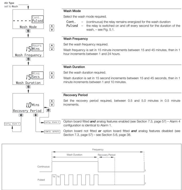
5.5.1 Wash Cycle Configuration (Applicable Only to Alarm 3)
Wash Mode
Select the wash mode required.
Cont. Pulsed
– –
(continuous) the relay remains energized for the wash duration the relay is switched on and off every second for the duration of the wash, – see Fig. 5.1.
Wash Frequency
Set the wash frequency required.
Wash frequency is set in 15 minute increments between 15 and 45 minutes, then in 1 hour increments between 1 and 24 hours.
Wash Duration
Set the wash duration required.
Wash duration is set in 15 second increments between 15 and 45 seconds, then in 1 minute increments between 1 and 10 minutes.
Recovery Period
Set the recovery period required, between 0.5 and 5.0 minutes in 0.5 minute increments.
Option board fitted and analog features enabled (see Section 7.3, page 57) – Alarm 4 configuration is identical to Alarm 1.
Option board not fitted or option board fitted and analog features disabled (see Section 7.3, page 57) – see Section 5.6, page 38.
Fig. 5.1 Pulsed and Continuous Wash Cycles
Wash Frequency Hours Mins Wash Duration
15
Recovery Period1.0
Mins15
CONFIG. OUTPUTS Config. Alarm 4 Config. Alarm 3 A3: Type set to Wash Wash Mode---
Cont.Pulsed Mins Secs Wash Duration Continuous Pulsed Recovery Period t t 1s 1s FrequencySingle and dual input analyzers for pH/Redox (ORP)
AX416, AX436, AX460, AX466 & AX468 5 Programming
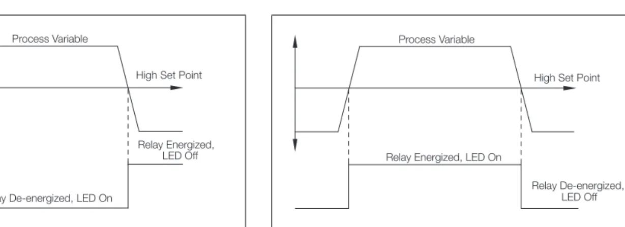
Note. The following examples illustrate High Alarm Actions, i.e. the alarm is activated when the process variable exceeds the defined set point. Low Alarm Actions are the same, except the alarm is activated when the process variable drops below the defined set point.
Fig. 5.2 High Failsafe Alarm without Hysteresis and Delay
Fig. 5.3 High Failsafe Alarm with Hysteresis but no Delay
Fig. 5.4 High Failsafe Alarm with Hysteresis and Delay
Relay Energized, LED Off Relay De-energized, LED On
Process Variable
High Set Point
Relay Energized, LED Off Relay De-energized, LED On
Process Variable
Hysteresis High Set Point
Relay Energized, LED Off Relay De-energized, LED On
Process Variable
High Set Point
Delay
Hysteresis
Fig. 5.5 High Non-Failsafe Alarm without Delay and Hysteresis
Fig. 5.6 High Failsafe Alarm with Delay but no Hysteresis
Relay De-energized, LED Off Relay Energized, LED On
Process Variable
High Set Point
Relay Energized, LED Off Relay De-energized, LED On
Process Variable
High Set Point
Single and dual input analyzers for pH/Redox (ORP)
AX416, AX436, AX460, AX466 & AX468 5 Programming
5.6 Configure Outputs
Configure Output 1
Output 2 configuration (and Outputs 3 and 4 if option board fitted and analog features enabled – see Section 7.3, page 57) is identical to Output 1 configuration.
Assign
Select the sensor and analog output required:
Sen.A
Sen.B – pH/Redox (ORP)/mV for the selected sensor. Temp.A
Temp.B – Temperature for the selected sensor.
A-B – Difference between the Sensor A and Sensor B readings. Note. Sen.B, Temp.B and A-B are applicable only to dual input analyzers. Range
Select the analog output current range for the selected output.
Span Value
pH (or mV or Deg.C or Deg.F or A-B) and Adjust are shown alternately on the upper display line. Use the and keys to adjust the displayed reading to the required span value.
Note. The minimum and maximum span values are determined by the Zero Value
setting (see next page) plus the minimum differential, e.g. to set Span Value to 0.00 pH, first set Zero Value to –2.00 pH.
pH Redox/ORP Temperature A-B – – – – 0.00 to 16.00 pH (minimum differential, 2.00 pH) –1100 to 1200 mV (minimum differential, 100 mV) Deg. C 0.0 to 150.0 (minimum differential, 10 ºC) Deg. F 32.0 to 302.0 (minimum differential,18 ºF) 0.00 to 14.00 pH (minimum differential, 2.00 pH) Note. A-B is applicable only to dual input analyzers.
Continued on next page.
Config. Output 1
---AO1: Assign ---AO1: Range ---CONFIG. OUTPUTS ---A-B Temp.B Sen.B Temp.A Sen.A 4-20mA 0-20mA 0-10mAAO1: Zero Value Config. Output 2
AO1: Span Value