Sun Microsystems, Inc. www.sun.com
Submit comments about this document at:http://www.sun.com/hwdocs/feedback
Sun Fire
™
T2000 Server
Installation Guide
Part No. 819-2546-11 April 2006, Revision A
Please
Copyright 2006 Sun Microsystems, Inc., 4150 Network Circle, Santa Clara, California 95054, U.S.A. All rights reserved.
Sun Microsystems, Inc. has intellectual property rights relating to technology that is described in this document. In particular, and without limitation, these intellectual property rights may include one or more of the U.S. patents listed at http://www.sun.com/patents and one or more additional patents or pending patent applications in the U.S. and in other countries.
This document and the product to which it pertains are distributed under licenses restricting their use, copying, distribution, and
decompilation. No part of the product or of this document may be reproduced in any form by any means without prior written authorization of Sun and its licensors, if any.
Third-party software, including font technology, is copyrighted and licensed from Sun suppliers.
Parts of the product may be derived from Berkeley BSD systems, licensed from the University of California. UNIX is a registered trademark in the U.S. and in other countries, exclusively licensed through X/Open Company, Ltd.
Sun, Sun Microsystems, the Sun logo, Java, AnswerBook2, docs.sun.com, Sun Fire, and Solaris are trademarks or registered trademarks of Sun Microsystems, Inc. in the U.S. and in other countries.
All SPARC trademarks are used under license and are trademarks or registered trademarks of SPARC International, Inc. in the U.S. and in other countries. Products bearing SPARC trademarks are based upon an architecture developed by Sun Microsystems, Inc.
The OPEN LOOK and Sun™ Graphical User Interface was developed by Sun Microsystems, Inc. for its users and licensees. Sun acknowledges the pioneering efforts of Xerox in researching and developing the concept of visual or graphical user interfaces for the computer industry. Sun holds a non-exclusive license from Xerox to the Xerox Graphical User Interface, which license also covers Sun’s licensees who implement OPEN LOOK GUIs and otherwise comply with Sun’s written license agreements.
U.S. Government Rights—Commercial use. Government users are subject to the Sun Microsystems, Inc. standard license agreement and applicable provisions of the FAR and its supplements.
DOCUMENTATION IS PROVIDED "AS IS" AND ALL EXPRESS OR IMPLIED CONDITIONS, REPRESENTATIONS AND WARRANTIES, INCLUDING ANY IMPLIED WARRANTY OF MERCHANTABILITY, FITNESS FOR A PARTICULAR PURPOSE OR NON-INFRINGEMENT, ARE DISCLAIMED, EXCEPT TO THE EXTENT THAT SUCH DISCLAIMERS ARE HELD TO BE LEGALLY INVALID.
Copyright 2006 Sun Microsystems, Inc., 4150 Network Circle, Santa Clara, Californie 95054, Etats-Unis. Tous droits réservés.
Sun Microsystems, Inc. a les droits de propriété intellectuels relatants à la technologie qui est décrit dans ce document. En particulier, et sans la limitation, ces droits de propriété intellectuels peuvent inclure un ou plus des brevets américains énumérés à http://www.sun.com/patents et un ou les brevets plus supplémentaires ou les applications de brevet en attente dans les Etats-Unis et dans les autres pays.
Ce produit ou document est protégé par un copyright et distribué avec des licences qui en restreignent l’utilisation, la copie, la distribution, et la décompilation. Aucune partie de ce produit ou document ne peut être reproduite sous aucune forme, par quelque moyen que ce soit, sans l’autorisation préalable et écrite de Sun et de ses bailleurs de licence, s’il y en a.
Le logiciel détenu par des tiers, et qui comprend la technologie relative aux polices de caractères, est protégé par un copyright et licencié par des fournisseurs de Sun.
Des parties de ce produit pourront être dérivées des systèmes Berkeley BSD licenciés par l’Université de Californie. UNIX est une marque déposée aux Etats-Unis et dans d’autres pays et licenciée exclusivement par X/Open Company, Ltd.
Sun, Sun Microsystems, le logo Sun, Java, AnswerBook2, docs.sun.com, Sun Fire, et Solaris sont des marques de fabrique ou des marques déposées de Sun Microsystems, Inc. aux Etats-Unis et dans d’autres pays.
Toutes les marques SPARC sont utilisées sous licence et sont des marques de fabrique ou des marques déposées de SPARC International, Inc. aux Etats-Unis et dans d’autres pays. Les produits portant les marques SPARC sont basés sur une architecture développée par Sun Microsystems, Inc.
L’interface d’utilisation graphique OPEN LOOK et Sun™ a été développée par Sun Microsystems, Inc. pour ses utilisateurs et licenciés. Sun reconnaît les efforts de pionniers de Xerox pour la recherche et le développement du concept des interfaces d’utilisation visuelle ou graphique pour l’industrie de l’informatique. Sun détient une license non exclusive de Xerox sur l’interface d’utilisation graphique Xerox, cette licence couvrant également les licenciées de Sun qui mettent en place l’interface d ’utilisation graphique OPEN LOOK et qui en outre se conforment aux licences écrites de Sun.
LA DOCUMENTATION EST FOURNIE "EN L’ÉTAT" ET TOUTES AUTRES CONDITIONS, DECLARATIONS ET GARANTIES EXPRESSES OU TACITES SONT FORMELLEMENT EXCLUES, DANS LA MESURE AUTORISEE PAR LA LOI APPLICABLE, Y COMPRIS NOTAMMENT TOUTE GARANTIE IMPLICITE RELATIVE A LA QUALITE MARCHANDE, A L’APTITUDE A UNE UTILISATION PARTICULIERE OU A L’ABSENCE DE CONTREFAÇON.
iii
Contents
Regulatory Compliance Statements xi Declaration of Conformity xv
Preface xvii
1. Preparing for Installation 1 Tools Needed 2
Shipping Kit Inventory List 2 Optional Component Installation 2 ESD Precautions 3
Installation Overview 3
Data Ports and Cabling Notes 5 Port Locations 5
Cabling Notes 6
Slide Rail Assembly Notes 8 Safety Precautions 10
2. Installing the Sun Fire T2000 Server 11 Installing the Server in a Rack 11
▼ To Install the Cable Management Kit 19
▼ To Verify the Operation of the Slide Rails and the CMA 23 Dismounting the Server 26
Connecting Cables to the Server 27 Connector Locations 27
▼ To Connect the Ethernet Network Cables 28
▼ To Connect the SC Serial Management Port 29
▼ To Connect the SC Network Management Port 29 AC Power Cables 30
TTYA Serial Port 30 USB Ports 31
Managing Cables With the CMA 31
▼ To Open and Close a Cable Clip 31
▼ To Move a Cable Clip 32
3. Powering On the System 35
Powering On the System for the First Time 35
Enabling the System Controller Network Management Port 38 Logging Into the System Controller 38
▼ To Log Into the System Controller Using the Serial Management Port 38
▼ To Configure the System Controller Network Management Port 39
▼ To Reset the System Controller 42
▼ To Log Into the System Controller Using the Network Management Port 43
Using the System Controller for Common Operations 44
▼ To Power On the System 44
▼ To Connect to the System Console 45
▼ To Perform a Normal System Initialization 45 Booting the Solaris Operating System 47
Contents v
▼ To Boot the Solaris Operating System 47
▼ To Reset the System 48
▼ To Power Cycle the System 48
A. Updating the Firmware 51
Updating the Firmware 51
▼ To Update the Firmware 51
B. Selecting a Boot Device 55
▼ To Select a Boot Device 55
vii
Figures
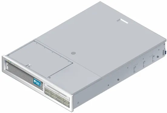
FIGURE 1-1 Sun Fire T2000 Server 1
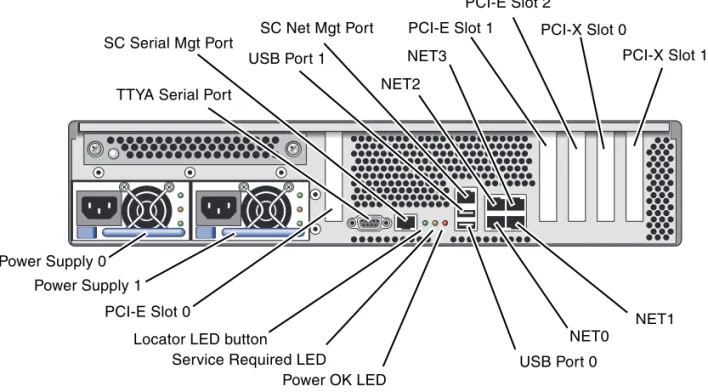
FIGURE 1-2 Rear Panel Features 6
FIGURE 1-3 Front Panel USB Ports 6
FIGURE 1-4 Sections of the Slide Rail Assembly 8
FIGURE 1-5 Locating the Locks on the Slide Rail Assembly 9
FIGURE 2-1 Unlocking the Slide Rail Assembly 12
FIGURE 2-2 Location of the Mounting Bracket Release Button 13
FIGURE 2-3 Unlocking the Slide Rail Middle Section 14
FIGURE 2-4 Attaching a Mounting Bracket to the Chassis 15
FIGURE 2-5 Mounting a Slide Rail 16
FIGURE 2-6 Using the Slide Rail Spacing Tool to Adjust the Distance Between the Slide Rails 17
FIGURE 2-7 Mounting the Chassis on the Slide Rails 18
FIGURE 2-8 Inserting the CMA Rail Extension Into the Rear of the Left Slide Rail 20
FIGURE 2-9 Mounting the Inner CMA Connector 21
FIGURE 2-10 Attaching the Outer CMA Connector 22
FIGURE 2-11 Mounting the Left Side of the Slide Rail 23
FIGURE 2-12 Unlocking the Slide Rail Assembly 24
FIGURE 2-13 Unlocking the Slide Rail Lever Stops 25
FIGURE 2-14 Slide Rail Release Button 26
FIGURE 2-16 Front Panel USB Ports 28
FIGURE 2-17 Ethernet Network Connections 28
FIGURE 2-18 System Controller Serial Connection 29
FIGURE 2-19 System Controller Network Connection 30
FIGURE 2-20 Serial Port 31
FIGURE 2-21 Opening a Cable Clip 32
FIGURE 2-22 Removing a Cable Clip 33
FIGURE 2-23 Mounting or Moving a Cable Clip 33
ix
Tables
TABLE 1-1 Ethernet Connection Transfer Rates 7
TABLE 3-1 Sample Configuration Parameter Settings 41
xi
Regulatory Compliance Statements
Your Sun product is marked to indicate its compliance class: • Federal Communications Commission (FCC) — USA
• Industry Canada Equipment Standard for Digital Equipment (ICES-003) — Canada • Voluntary Control Council for Interference (VCCI) — Japan
• Bureau of Standards Metrology and Inspection (BSMI) — Taiwan
Please read the appropriate section that corresponds to the marking on your Sun product before attempting to install the product.
FCC Class A Notice
This device complies with Part 15 of the FCC Rules. Operation is subject to the following two conditions: 1. This device may not cause harmful interference.
2. This device must accept any interference received, including interference that may cause undesired operation.
Note: This equipment has been tested and found to comply with the limits for a Class A digital device, pursuant to Part 15 of the FCC Rules. These limits are designed to provide reasonable protection against harmful interference when the equipment is operated in a commercial environment. This equipment generates, uses, and can radiate radio frequency energy, and if it is not installed and used in accordance with the instruction manual, it may cause harmful interference to radio communications. Operation of this equipment in a residential area is likely to cause harmful interference, in which case the user will be required to correct the interference at his own expense.
Shielded Cables: Connections between the workstation and peripherals must be made using shielded cables to comply with FCC radio frequency emission limits. Networking connections can be made using unshielded twisted-pair (UTP) cables.
Modifications: Any modifications made to this device that are not approved by Sun Microsystems, Inc. may void the authority granted to the user by the FCC to operate this equipment.
FCC Class B Notice
This device complies with Part 15 of the FCC Rules. Operation is subject to the following two conditions: 1. This device may not cause harmful interference.
2. This device must accept any interference received, including interference that may cause undesired operation.
Note: This equipment has been tested and found to comply with the limits for a Class B digital device, pursuant to Part 15 of the FCC Rules. These limits are designed to provide reasonable protection against harmful interference in a residential installation. This equipment generates, uses and can radiate radio frequency energy and, if not installed and used in accordance with the instructions, may cause harmful interference to radio communications. However, there is no guarantee that interference will not occur in a particular installation. If this equipment does cause harmful interference to radio or television reception, which can be determined by turning the equipment off and on, the user is encouraged to try to correct the interference by one or more of the following measures:
• Reorient or relocate the receiving antenna.
• Increase the separation between the equipment and receiver.
• Connect the equipment into an outlet on a circuit different from that to which the receiver is connected. • Consult the dealer or an experienced radio/television technician for help.
Shielded Cables: Connections between the workstation and peripherals must be made using shielded cables to comply with FCC radio frequency emission limits. Networking connections can be made using unshielded twisted-pair (UTP) cables.
Modifications: Any modifications made to this device that are not approved by Sun Microsystems, Inc. may void the authority granted to the user by the FCC to operate this equipment.
ICES-003 Class A Notice - Avis NMB-003, Classe A
This Class A digital apparatus complies with Canadian ICES-003.
Cet appareil numérique de la classe A est conforme à la norme NMB-003 du Canada.
ICES-003 Class B Notice - Avis NMB-003, Classe B
This Class B digital apparatus complies with Canadian ICES-003.
Regulatory Compliance Statements xiii
BSMI Class A Notice
The following statement is applicable to products shipped to Taiwan and marked as Class A on the product compliance label.
CCC Class A Notice
The following statement is applicable to products shipped to China and marked with “Class A” on the product’s compliance label.
GOST-R Certification Mark
xv
Declaration of Conformity
EMC
USA—FCC Class A
This equipment complies with Part 15 of the FCC Rules. Operation is subject to the following two conditions: 1. This equipment may not cause harmful interference.
2. This equipment must accept any interference that may cause undesired operation. European Union
This equipment complies with the following requirements of the EMC Directive 89/336/EEC:
Safety:This equipment complies with the following requirements of the Low Voltage Directive 73/23/EEC:
Supplementary Information:This equipment was tested and complies with all the requirements for the CE Mark. This equipment complies with the Restriction of Hazardous Substances (RoHS) directive 2002/95/EC.
Compliance Model Number: T2000
Product Family Name: Sun Fire T2000 server
As Telecommunication Network Equipment (TNE) in Both Telecom Centers and Other Than Telecom Centers per (as applicable):
EN 300 386 V.1.3.2 (2003-05) Required Limits: EN 55022:1994 +A1:1995 +A2:1997 Class A EN 61000-3-2:2000 Pass EN 61000-3-3:1995 +A1:2000 Pass
IEC 61000-4-2 6 kV (Direct), 8 kV (Air)
IEC 61000-4-3 3 V/m 80-1000MHz, 10 V/m 800-960 MHz, and 1400-2000 MHz IEC 61000-4-4 1 kV AC and DC Power Lines, 0.5 kV Signal Lines
IEC 61000-4-5 2 kV AC Line-Gnd, 1 kV AC Line-Line and Outdoor Signal Lines, 0.5 kV Indoor signal Lines > 10m. IEC 61000-4-6 3 V
IEC 61000-4-11 Pass
As Information Technology Equipment (ITE) Class A per (as applicable):
EN 55022:1994 +A1:1995 +A2:1997 Class A EN 61000-3-2:2000 Pass EN 61000-3-3:1995 +A1:2000 Pass
EN 55024:1998 +A1:2001 +A2:2003 Required Limits: IEC 61000-4-2 4 kV (Direct), 8 kV (Air) IEC 61000-4-3 3 V/m
IEC 61000-4-4 1 kV AC Power Lines, 0.5 kV Signal and DC Power Lines
IEC 61000-4-5 1 kV AC Line-Line and Outdoor Signal Lines, 2 kV AC Line-Gnd, 0.5 kV DC Power Lines IEC 61000-4-6 3 V
IEC 61000-4-8 1 A/m IEC 61000-4-11 Pass
EC Type Examination Certificates:
EN 60950-1:2001, 1st Edition UL/DEMKO/GS Certificate No. 140 169-02/1407 IEC 60950-1:2001, 1st Edition CB Scheme Certificate No. US/9794/UL Evaluated to all CB Countries
UL 60950:2003, 1st Edition, CSA C22.2 No. 60950-01-03 File: E138989-A50-UL-1
/S/ /S/
Dennis P. Symanski DATE
Worldwide, Compliance Office Sun Microsystems, Inc. 4150 Network Circle, MPK15-102 Santa Clara, CA 95054 U.S.A. Tel: 650-786-3255
Fax: 650-786-3723
Donald Cameron DATE
Program Manager/Quality Systems Sun Microsystems Scotland, Limited Blackness Road, Phase I, Main Bldg. Springfield, EH49 7LR
Scotland, United Kingdom
xvii
Preface
TheSun Fire T2000 Server Installation Guideprovides instructions, background information, and reference material to help you install a Sun Fire T2000 server. Instructions for installation in the document assume that a system administrator is experienced with the Solaris™Operating System (Solaris OS).
Note – All internal components except hard drives must be installed by qualified service technicians only.
How This Document Is Organized
This guide is organized in this way:Chapter 1provides an installation overview for the Sun Fire T2000 server.
Chapter 2provides instructions for installing the Sun Fire T2000 server into a rack. Chapter 3provides instructions for configuring and powering on the server and for installing additional software.
Appendix Aprovides instructions for updating the system controller firmware and the host firmware.
Using UNIX Commands
This document might not contain information about basic UNIX®commands and procedures such as shutting down the system, booting the system, and configuring devices. Refer to the following for this information:
■ Software documentation that you received with your system ■ Solaris™ Operating System documentation, which is at:
http://docs.sun.com
Shell Prompts
Typographic Conventions
Shell Prompt
C shell machine-name%
C shell superuser machine-name#
Bourne shell and Korn shell $
Bourne shell and Korn shell superuser #
Typeface* Meaning Examples
AaBbCc123 The names of commands, files, and directories; on-screen computer output
Edit your.loginfile. Use ls -ato list all files. % You have mail. AaBbCc123 What you type, when contrasted
with on-screen computer output
% su
Password:
AaBbCc123 Book titles, new words or terms, words to be emphasized. Replace command-line variables with real names or values.
Read Chapter 6 in theUser’s Guide. These are calledclassoptions. Youmustbe superuser to do this. To delete a file, typermfilename.
Preface xix
Related Documentation
The documents listed as online are available at: http://www.sun.com/documentation
* The settings on your browser might differ from these settings.
Title Description Part Number
Sun Fire T2000 Server Site Planning Guide Site planning information for the Sun Fire T2000 server
819-2545-xx
Sun Fire T2000 Server Product Notes Late breaking information about the server. The latest notes are posted at: http://www.sun.com/documentati on
819-2544-xx
Sun Fire T2000 Server Getting Started Guide Information about where to find documentation to get your system installed and running quickly
819-2542-xx
Sun Fire T2000 Server Administration Guide How to perform administrative tasks that are specific to the Sun Fire T2000 server
819-2549-xx
Sun Fire T2000 Server Service Manual How to run diagnostics to troubleshoot your server and how to remove and replace parts in the server
819-2548-xx
Advanced Lights Out Management (ALOM) CMT v1.1 Guide
How to use the Advanced Lights Out Management (ALOM) software on the Sun Fire T2000 server
Documentation, Support, and Training
Third-Party Web Sites
Sun is not responsible for the availability of third-party web sites mentioned in this document. Sun does not endorse and is not responsible or liable for any content, advertising, products, or other materials that are available on or through such sites or resources. Sun will not be responsible or liable for any actual or alleged damage or loss caused by or in connection with the use of or reliance on any such content, goods, or services that are available on or through such sites or resources.
Sun Welcomes Your Comments
Sun is interested in improving its documentation and welcomes your comments and suggestions. You can submit your comments by going to:
http://www.sun.com/hwdocs/feedback
Please include the title and part number of your document with your feedback:
Sun Fire T2000 Server Installation Guide, part number 819-2546-11
Sun Function URL Description
Documentation http://www.sun.com/documentation/ Download PDF and HTML documents, and order printed documents
Support and Training
http://www.sun.com/supportraining/ Obtain technical support, download patches, and learn about Sun courses
1 C H A P T E R
1
Preparing for Installation
This chapter provides background information about the Sun Fire™ T2000 server installation procedures that are provided inChapter 2.
This chapter contains these topics:
■ “Tools Needed” on page 2
■ “Shipping Kit Inventory List” on page 2 ■ “Optional Component Installation” on page 2 ■ “Installation Overview” on page 3
■ “Data Ports and Cabling Notes” on page 5 ■ “Slide Rail Assembly Notes” on page 8 ■ “Safety Precautions” on page 10
Tools Needed
■ #2 Phillips screwdriver ■ ESD mat and grounding strap
Shipping Kit Inventory List
Standard components of Sun Fire T2000 server are installed at the factory. However, if you ordered options such as a PCI card and monitor, these are shipped to you separately.
Note –Inspect the shipping carton(s) for evidence of physical damage. If a shipping carton appears damaged, request that the carrier’s agent be present when the carton is opened. Keep all contents and packing material for the agent’s inspection.
● Verify that you have received all the parts of your server.
1. Sun Fire T2000 server chassis 2. Slide rail assemblies
3. Package of mounting screws and nuts in assorted sizes to fit various types of racks and cabinets
4. Cable management arm with six preinstalled cable clips
5. Manufacturer’s instruction sheet for the cable management arm 6. Any optional components that were ordered with the server.
Optional Component Installation
The standard components of the Sun Fire T2000 server are installed at the factory. However, if you ordered options such as additional memory or a PCI card, these will be shipped separately. If possible, install these components prior to installing the server in a rack.
Chapter 1 Preparing for Installation 3 If you ordered any options that are not factory-installed, see theSun Fire T2000 Server Service Manualfor installation instructions.
Note –The list of optional components can be updated without notice. Refer to the SunSMStore web site (http://store.sun.com) for the most current list of components supported in the Sun Fire T2000 server.
ESD Precautions
Electronic equipment is susceptible to damage by static electricity. Use a grounded antistatic wriststrap, footstrap, or equivalent safety equipment to prevent
electrostatic damage (ESD) when you install or service the Sun Fire T2000 server. Caution – To protect electronic components from electrostatic damage, which can permanently disable the system or require repair by Sun service technicians, place components on an antistatic surface, such as an antistatic discharge mat, an antistatic bag, or a disposable antistatic mat. Wear an antistatic grounding strap connected to a metal surface on the chassis when you work on system components.
Installation Overview
This installation guide provides procedures which are to be performed in the following order.
1. Verify that you have received all of the components that ship with your server. See“Shipping Kit Inventory List” on page 2.
2. Gather configuration information for your system. See your system administrator for specific details, including these parameters:
■ Netmask
■ IP address for the system controller ■ Gateway IP address
3. Install any optional Sun™ components shipped with your system. If you have purchased other optional components such as additional memory, install them prior to mounting the server in a rack. See“Optional Component Installation” on page 2.
4. Mount the server into a rack or cabinet. See“Installing the Server in a Rack” on page 11.
Note – In the rest of this manual, the termrackmeans either an open rack or a closed cabinet.
5. Connect the server to a serial terminal or a terminal emulator (PC or workstation) to display system messages. See“Powering On the System for the First Time” on page 35.
Tip – The serial terminal or a terminal emulator should be connected before you connect the power cables, or you will not see the system messages.
6. Connect the data cables to the server, but do not connect the AC power cable yet. See“Connecting Cables to the Server” on page 27.
7. Connect the AC power cable to the server and examine the display for any error messages. See“Powering On the System for the First Time” on page 35.
Caution –There is a potential for electric shock if the server and related equipment are not properly grounded.
Note –The system controller (SC) runs on the 3.3v standby voltage. As soon as AC power is connected to the system, the system controller immediately powers on, runs diagnostics, and initializes the ALOM-CMT firmware.
8. After the system controller boots, access the ALOM-CMT command line interface through the serial management port. See“To Log Into the System Controller Using the Serial Management Port” on page 38.
9. Configure the SC network addresses. See“To Configure the System Controller
Network Management Port” on page 39.
Note – The SC network management port is not operational until you configure network settings for the system controller (through the SC serial management port). 10. Enable the new configuration by resetting the system controller. See“To Reset
the System Controller” on page 42.
11. Power on the server from a keyboard using the ALOM-CMT software. See“To Power On the System” on page 44.
Chapter 1 Preparing for Installation 5 12. Configure the Solaris™ OS. See“Booting the Solaris Operating System” on
page 47.
The Solaris OS is preinstalled on the server. When you power on, you are automatically guided through the Solaris OS configuration procedure. 13. Install any required patch or patches to the server.
Refer to theSun Fire T2000 Server Product Notesfor a list of the required patches. 14. Load additional software from the Solaris media kit (optional).
The Solaris media kit (sold separately) includes several CDs containing software to help you operate, configure, and administer your server. Refer to the
documentation provided with the media kit for a complete listing of included software and detailed installation instructions.
Data Ports and Cabling Notes
Port Locations
SeeFIGURE 1-2andFIGURE 1-3for the locations of the ports on the Sun Fire T2000 server.
FIGURE 1-2 Rear Panel Features
USB ports 2 and 3 are located on the front panel (FIGURE 1-3).
FIGURE 1-3 Front Panel USB Ports
Cabling Notes
■ Minimum cable connections for the Sun Fire T2000 system:
■ At least one system on-board Ethernet network connection (NET port) ■ The system controller serial management port (SERIAL MGT port) ■ The system controller network management port (NET MGT port) ■ Power cables for the two system power supplies
■ System controller (SC) management ports:There are two SC management ports for use with the ALOM system controller.
Power Supply 0 Power Supply 1 PCI-E Slot 0 SC Serial Mgt Port SC Net Mgt Port USB Port 0 USB Port 1 NET2 NET0 Locator LED button
Service Required LED
Power OK LED NET3 NET1 PCI-E Slot 1 PCI-E Slot 2 PCI-X Slot 1 PCI-X Slot 0
TTYA Serial Port
USB Port2 USB Port3
Chapter 1 Preparing for Installation 7
■ The SC serial management port(labeled SERIAL MGT) uses an RJ-45 cable
and is always available. This is the default connection to the ALOM-CMT system controller.
■ The SC network management port(labeled NET MGT) is the optional
connection to the ALOM-CMT system controller. This port is not available until you have configured network settings for the system controller (through the SC serial management port). See“Enabling the System Controller Network
Management Port” on page 38. The SC network management port uses an
RJ-45 cable for a 10/100 BASE-T connection. This port does not support connections to Gigabit networks.
■ See theSun Fire T2000 Server Overviewfor more information.
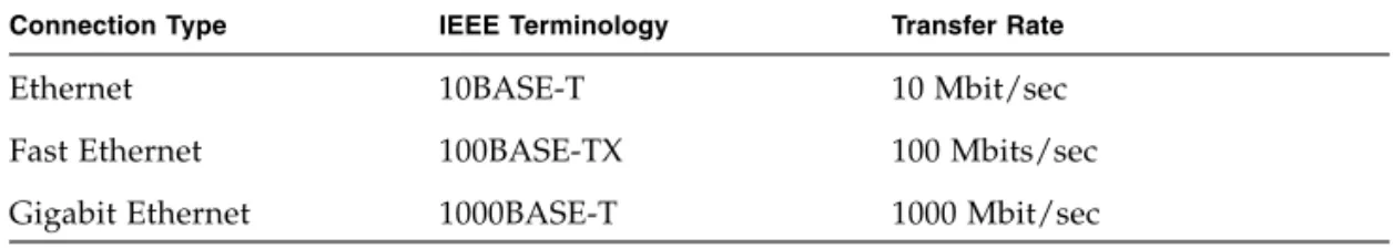
■ Ethernet portsare labeled NET0, NET1, NET2, and NET3. The Sun Fire T2000 Ethernet interfaces operate at 10 Mbps, 100 Mbps, and 1000 Mbps. The transfer rates for the Ethernet ports are given inTABLE 1-1.
■ TTYA serial port:Use the Sun Fire T2000 DB-9 connector with a null modem cable for serial devices. This port appears asttyain Solaris OS and OpenBoot messages. This port is not connected to the SC serial management port.
■ USB Ports:USB ports support hot-plugging. You can connect and disconnect USB cables and peripheral devices while the system is running, without affecting system operations.
■ You can only perform USB hot-plug operations while the OS is running. USB
hot-plug operations are not supported when the systemokprompt is displayed or before the system has completed booting.
■ You can connect up to 126 devices to each of the two USB controllers, for a
total of 252 USB devices per system.
■ AC power cables:Do not attach power cables to the Sun Fire T2000 power supplies until you have finished connecting the data cables, and have connected the server to a serial terminal or a terminal emulator (PC or workstation). The server goes into standby mode and the ALOM-CMT system controller initializes as soon as the AC power cables are connected to the power source. System messages may be lost after 60 seconds if the server is not connected to a terminal, PC, or workstation.
TABLE 1-1 Ethernet Connection Transfer Rates
Connection Type IEEE Terminology Transfer Rate
Ethernet 10BASE-T 10 Mbit/sec
Fast Ethernet 100BASE-TX 100 Mbits/sec
Slide Rail Assembly Notes
The rackmount kit has twoslide rail assemblies. A slide rail assembly can be installed on either the right or left side of the rack.
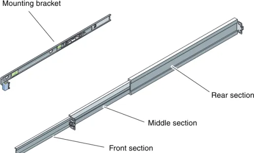
Each slide rail assembly consists of a three-section slide rail and a removeable mounting bracket (FIGURE 1-4).
FIGURE 1-4 Sections of the Slide Rail Assembly
■ Thefront,middle, andrearsections form theslide rail. The middle and rear sections have holes for mounting screws and adjust to fit rack depths from 24 in (61 cm) to 36.5 in (93 cm). The front section can be extended to allow movement of the server out of the rack.
■ The removeablemounting bracketslides 14 in (36 cm) out of the slide rail, then locks in place. If you unlock the mounting bracket at this point, it slides an additional 12 in (30 cm) before separating from the slide rail. You can then mount the mounting bracket to the right or left side of the Sun Fire T2000 chassis. ■ Note that there are a total of five locks (FIGURE 1-5) in a slide rail assembly. Four
are on the mounting bracket. One lock is on the front section of the slide rail. The uses of these locks are described in the installation procedure inChapter 2. Mounting bracket
Rear section
Front section
Chapter 1 Preparing for Installation 9 FIGURE 1-5 Locating the Locks on the Slide Rail Assembly
Safety Precautions
Caution – Deploy the anti-tilt bar on the cabinet or rack before beginning an installation.
Caution – The server weighs approximately 40 lb (18 kg). Two people are required to lift and mount the system into a rack enclosure when using the procedures in this chapter.
Caution – When completing a two-person procedure, always communicate your intentions clearly before, during, and after each step to minimize confusion.
11 C H A P T E R
2
Installing the Sun Fire T2000 Server
This chapter provides instructions for installing the Sun Fire T2000 server in an open rack or closed cabinet.This chapter contains the following sections: ■ “Installing the Server in a Rack” on page 11 ■ “Connecting Cables to the Server” on page 27
■ “Managing Cables With the CMA” on page 31
Note – References toleftandrightare from your viewpoint as you face either the front or rear of the equipment.
Installing the Server in a Rack
Note – Ensure that you have all of the parts in the rackmount kit before you begin the installation of the server. See“Shipping Kit Inventory List” on page 2.
The rackmount kit contains two slide rail assemblies. A slide rail assembly can be installed on either the right or left side of the rack.
A slide rail assembly consists of two parts: a slide rail and a removeable mounting bracket. The slide rail attaches to the rack posts. The mounting bracket, attaches to the Sun Fire T2000 chassis.
▼
To Install the Slide Rail Assemblies
1. Pull both mounting brackets completely out of their respective slide rails: a. Simultaneously press and hold the upper and lower lock buttons of the slide
rail lock (FIGURE 2-1).
FIGURE 2-1 Unlocking the Slide Rail Assembly
b. Pull the mounting bracket out until it locks in the extended position.
c. Slide the mounting bracket release button in the direction shown inFIGURE 2-2, then slide the mounting bracket out of the slide rail.
Chapter 2 Installing the Sun Fire T2000 Server 13 FIGURE 2-2 Location of the Mounting Bracket Release Button
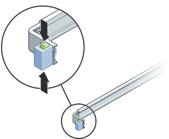
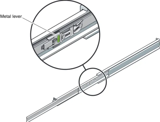
d. Press the metal lever (labeled Push) on the middle section (FIGURE 2-3) of the sliding rail, then push the middle section back into the rack.
FIGURE 2-3 Unlocking the Slide Rail Middle Section
2. Attach a mounting bracket to the right side of the Sun Fire T2000 chassis.
a. Position the mounting bracket against the server chassis (FIGURE 2-4) so that the slide rail lock is at the front and the three keyed openings on the mounting bracket are aligned with the three locating pins on the side of the chassis. Metal lever
Chapter 2 Installing the Sun Fire T2000 Server 15 FIGURE 2-4 Attaching a Mounting Bracket to the Chassis
b. With the heads of the three locating pins protruding though the three keyed openings in the mounting bracket, pull the mounting bracket toward the front of the chassis until the bracket locks into place with an audibleclick.
c. Verify that all three locating pins are trapped in the keyed openings and that the rear locating pin has engaged the mounting bracket lock, as shown in the right side ofFIGURE 2-4.
3. Attach the second mounting bracket to the left side of the Sun Fire T2000 chassis. 4. Determine which rack hole numbers to use when attaching the slide rails to the
rack posts.
The Sun Fire T2000 server is two rack units tall (2 RU). The slide rails will occupy the lower half of the 2 RU space.
5. Determine which screws you will use to mount the slide rails.
If your rack has threaded mounting holes in the rack posts, determine whether the threads are metric or standard. Select the appropriate screws from the package included in the mounting kit.
If your rack does not have threaded mounting holes, the mounting screws are secured with a caged nut.
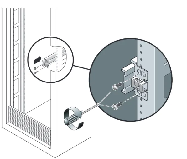
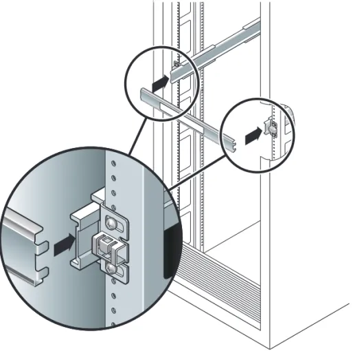
6. Attach a slide rail to the right front rack post.
a. Loosely attach the front of a slide rail to the right front rack post (FIGURE 2-5) using two screws.
Note – Do not tighten the screws yet.
FIGURE 2-5 Mounting a Slide Rail
b. Adjust the length of the slide rail by sliding the rear mounting flange to reach the outside edge of the rear rack post.
Chapter 2 Installing the Sun Fire T2000 Server 17
c. Loosely attach the rear of the slide rail to the rear rack post with two screws. 7. Attach the second slide rail to the left rack posts in a similar manner. Again, do
not tighten the screws.
8. Use the slide rail spacing tool to adjust the distance between the slide rails: a. At the front of the rack, plug the left side of the tool into slots at the end of the
left rail (FIGURE 2-6).
FIGURE 2-6 Using the Slide Rail Spacing Tool to Adjust the Distance Between the Slide Rails
b. Insert the right side of the tool into the front end of the right rail, while sliding the end of the rail to the right or left as needed to allow the the ends of the tool to enter the ends of both rails.
The distance between the rails is now equal to the width of the server with mounting brackets.
d. At the rear of the rack, repeatStep athroughStep c. for the rear ends of the rails.
9. Deploy the anti-tilt bar, if the chassis or rack is so equipped.
Caution – The weight of the server on extended slide rails can be enough to overturn a cabinet.
Caution – The server weighs approximately 40 lb (18 kg). Two people are required to lift and mount the system into a rack enclosure when using the procedures in this chapter.
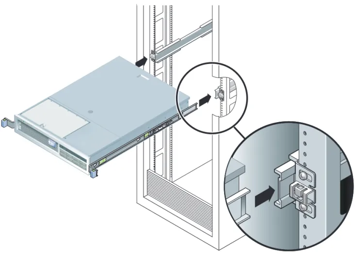
10. Insert the ends of the mounting brackets into the sliding rails (FIGURE 2-7).
Chapter 2 Installing the Sun Fire T2000 Server 19
11. Slide the chassis into the rack.
Caution – Verify that the server is securely mounted in the rack, and that the slide rails are locked to the mounting brackets, before continuing.
▼
To Install the Cable Management Kit
The cable management assembly (CMA) clips into the ends of the left and right sliding rail assemblies. No screws are necessary for mounting the CMA.
Caution – Support the CMA during this installation. Do not allow the assembly to hang by its own weight until it is secured by all three attachment points.
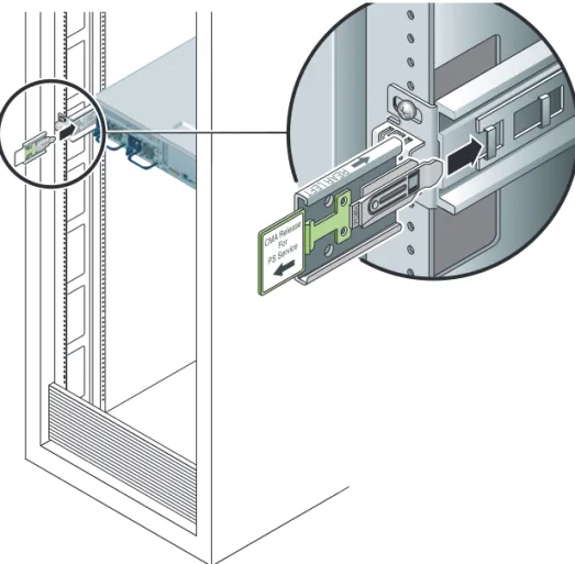
1. At the rear of the rack, plug the CMA rail extension into the end of the left sliding rail assembly (FIGURE 2-8). The tab at the front of the rail extension will click into place.
FIGURE 2-8 Inserting the CMA Rail Extension Into the Rear of the Left Slide Rail The right sides of the two CMA arms have hinged extensions. On the
manufacturer’s instruction sheet, the smaller extension is called the CMA Connector for Inner Member. It attaches to the right mounting bracket. The larger extension is called the CMA Connector for Outer Member, and attaches to the right sliding rail.
2. Insert the smaller extension into the clip located at the end of the mounting bracket (FIGURE 2-9).
Chapter 2 Installing the Sun Fire T2000 Server 21 FIGURE 2-9 Mounting the Inner CMA Connector
FIGURE 2-10 Attaching the Outer CMA Connector
4. Insert the hinged plastic connector at the left side of the CMA fully into the CMA rail extension (FIGURE 2-11).
The plastic tab on the CMA rail extension locks the hinged plastic connector in place.
Chapter 2 Installing the Sun Fire T2000 Server 23 FIGURE 2-11 Mounting the Left Side of the Slide Rail
▼
To Verify the Operation of the Slide Rails and
the CMA
Tip – Two people are needed this procedure: one to move the server in and out of the rack and one to observe the cables and CMA.
1. For a cabinet or a free-standing rack, deploy the anti-tilt bar.
2. Unlock the slide lock buttons (FIGURE 2-12) at the right and lefts sides of the server chassis, and slowly pull the server out of the rack until the slide rails reach their stops.
FIGURE 2-12 Unlocking the Slide Rail Assembly
3. Inspect the attached cables for any binding or kinks.
4. Verify that the CMA extends fully and does not bind in the slide rails. 5. When the server is fully extended out, release the slide rail lever stops
(FIGURE 2-13).
Chapter 2 Installing the Sun Fire T2000 Server 25 FIGURE 2-13 Unlocking the Slide Rail Lever Stops
6. Simultaneously unlock both slide rail release buttons (FIGURE 2-14),and push the server completely into the rack.
FIGURE 2-14 Slide Rail Release Button
The server should stop after approximately 15 inches (40 cm) of travel.
7. Verify that the cables and the CMA retracted without binding. 8. Adjust the cable hangers and CMA as required.
Dismounting the Server
If it becomes necessary to remove the server from the rack, or to open the server case for maintenance or hardware upgrades, refer to theSun Fire T2000 Server Service Manualfor procedures.
Chapter 2 Installing the Sun Fire T2000 Server 27
Connecting Cables to the Server
■ “To Connect the Ethernet Network Cables” on page 28
■ “To Connect the SC Network Management Port” on page 29
■ “To Connect the SC Serial Management Port” on page 29
■ “AC Power Cables” on page 30
In addition, the Sun Fire T2000 server has serial and USB ports available for connections to optional devices.
■ “TTYA Serial Port” on page 30
■ “USB Ports” on page 31
Connector Locations
UseFIGURE 2-15to locate the connectors and power supplies on the back of the Sun Fire T2000 server.
FIGURE 2-15 Rear Panel Features
USB ports 2 and 3 are located on the front panel (FIGURE 2-16). Power Supply 0 Power Supply 1 PCI-E Slot 0 SC Serial Mgt Port SC Net Mgt Port USB Port 0 USB Port 1 NET2 NET0 Locator LED button
Service Required LED
Power OK LED NET3 NET1 PCI-E Slot 1 PCI-E Slot 2 PCI-X Slot 1 PCI-X Slot 0
FIGURE 2-16 Front Panel USB Ports
▼
To Connect the Ethernet Network Cables
The Sun Fire T2000 has four RJ-45 Gigabit Ethernet network connectors. They are marked NET0, NET1, NET2, and NET3 (FIGURE 2-17).
FIGURE 2-17 Ethernet Network Connections
1. Connect a Category 5 cable from your network switch or hub to Ethernet Port 0 (NET0) on the rear of the chassis.
2. As needed, connect Category 5 cables from your network switch or hub to the remaining Ethernet ports (NET1, NET2, NET3).
USB Port2 USB Port3 NET0 NET1 NET2 NET3
Chapter 2 Installing the Sun Fire T2000 Server 29
▼
To Connect the SC Serial Management Port
Use this port for server management. This port is needed to set up the SC network management port, as detailed in“Enabling the System Controller Network
Management Port” on page 38.
The SC serial management port is marked SER MGT. It is the leftmost RJ-45 port on the rear of the chassis (FIGURE 2-18).
FIGURE 2-18 System Controller Serial Connection
● Connect a Category 5 cable from the SC serial management port to the terminal device.
▼
To Connect the SC Network Management Port
The SC network management port is marked NET MGT. It is the RJ-45 port above the rear USB ports.
Note – This port is not operational until you configure the network settings (through the serial managment port), as detailed in“To Configure the System Controller Network Management Port” on page 39.
FIGURE 2-19 System Controller Network Connection
● Connect a Category 5 cable from your network switch or hub to the Network Management Port.
AC Power Cables
Note – Finish the hardware procedures in this chapter, but do not attach the AC power cables yet.
Powering on the system for the first time requires special preparation and
procedures. For example, if you have not prepared a display before connecting the AC power cables, system messages may be lost. You will be instructed to connect the server to AC power in“Powering On the System for the First Time” on page 35. Caution – The server goes into standby mode and the system controller initializes as soon as the AC power cables are connected to the power source.
TTYA Serial Port
The TTYA serial port connector uses a DB-9 connector (item 1 inFIGURE 2-20). Use this port for general purpose serial data transfers. This port is not connected to the SC serial management port.
Chapter 2 Installing the Sun Fire T2000 Server 31 FIGURE 2-20 Serial Port
Use a null modem cable or an adapter to perform the crossovers given for each connector.
■ If connecting to a serial port on a personal computer, you can use Sun adapter part number 530-3100-01.
■ If connecting to a Sun workstation or server, you can use Sun adapter part number 530-2889-03.
USB Ports
Four Universal Serial Bus (USB) ports are provided on the Sun Fire T2000 server. USB ports 0 and 1 are located on the rear of the chassis (FIGURE 2-15). Ports 2 and 3 on the front of the chassis (FIGURE 2-16).
Managing Cables With the CMA
▼
To Open and Close a Cable Clip
1. To open a cable clip, press the front of the cable clip and lift the hinged top. 2. Route cables through the clip, then press the top of the cable clip to lock.
FIGURE 2-21 Opening a Cable Clip
▼
To Move a Cable Clip
1. To remove a cable clip from the CMA arm, lift the cable clip approximately 3/8 in (10 mm) to free the lower clip lock, then rotate the entire clip about 90 degrees to free the upper clip lock.
Chapter 2 Installing the Sun Fire T2000 Server 33 FIGURE 2-22 Removing a Cable Clip
2. To insert a cable clip, position the upper and lower clip locks in the slots of the CMA arm, then press the clip down approximately 3/8 in (10 mm).
35 C H A P T E R
3
Powering On the System
This chapter includes instructions for booting the Sun Fire T2000 system and for enabling the system controller network management port.
The following topics are discussed:
■ “Powering On the System for the First Time” on page 35
■ “Enabling the System Controller Network Management Port” on page 38
■ “Logging Into the System Controller” on page 38
■ “Using the System Controller for Common Operations” on page 44
■ “Booting the Solaris Operating System” on page 47
Powering On the System for the First
Time
Tip – The serial terminal or a terminal emulator should be connected before you connect the power cables, or you will not see the system messages. The server goes into standby mode and the ALOM-CMT system controller initializes as soon as the AC power cables are connected to the power source.
Note –If you are not logged in, ALOM-CMT times out after 60 seconds and reverts to the system console. For more information, refer to theSun Fire T2000 Server Advanced Lights Out Management (ALOM) Guide.
The system controller runs on the 3.3v standby voltage. As soon as AC power is connected to the system, the system controller powers on, runs diagnostics, and initializes the ALOM-CMT firmware.
1. If you have not already done so, connect a terminal or a terminal emulator (PC or workstation) to the SC serial management port.Configure the terminal or terminal emulator with these settings:
■ 9600 baud ■ 8 bits ■ No parity ■ 1 Stop bit ■ No handshaking
Note – When you power on the server for the first time and you do not have a terminal or terminal emulator (PC or workstation) connected to the SC serial management port, you will not see system messages. The display times out and disappears after about 60 seconds.
2. Turn on the terminal or terminal emulator.
3. Connect the AC power cables to Power Supply 0 and Power Supply 1, and watch the terminal for system messages.
FIGURE 3-1 Rear Panel Power Connectors
After the system controller boots, the system controller login prompt is displayed on the serial console. The following example shows a partial output from the system controller boot sequence leading to the login prompt.
CODE EXAMPLE 3-1 Sample System Controller Output
ALOM POST 1.0
Dual Port Memory Test, PASSED.
TTY External - Internal Loopback Test Power supply 0 Power supply 1
Chapter 3 Powering On the System 37 TTY External - Internal Loopback Test, PASSED.
TTYC - Internal Loopback Test
TTYC - Internal Loopback Test, PASSED. TTYD - Internal Loopback Test
TTYD - Internal Loopback Test, PASSED. ...
Full VxDiag Tests - PASSED
Status summary - Status = 7FFF VxDiag - - PASSED POST - - PASSED LOOPBACK - - PASSED I2C - - PASSED EPROM - - PASSED FRU PROM - - PASSED ETHERNET - - PASSED MAIN CRC - - PASSED BOOT CRC - - PASSED TTYD - - PASSED TTYC - - PASSED MEMORY - - PASSED MPC885 - - PASSED Please login:
Enabling the System Controller Network
Management Port
The system controller network management port is not operational until you configure network settings for the system controller. Configure the system controller in this order:
1. After the system controller boots, access the ALOM-CMT command line interface through the serial management port. See“To Log Into the System Controller Using the Serial Management Port” on page 38.
2. Configure the system controller. See“To Configure the System Controller
Network Management Port” on page 39.
3. Enable the new values by resetting the system controller. See“To Reset the System Controller” on page 42.
You can now use the SP network management port at any time to access the system controller. See“To Log Into the System Controller Using the Network Management Port” on page 43.
Logging Into the System Controller
If you are powering on the system for the first time after installation, use the system controller serial port to power on the system and run POST. See“To Log Into the System Controller Using the Serial Management Port” on page 38.
If the network management port has already been configured, you can use it instead of the serial management port. See“To Log Into the System Controller Using the
Network Management Port” on page 43.
▼
To Log Into the System Controller Using the
Serial Management Port
After the system controller boots you can access the ALOM-CMT command line interface to configure and manage the system.
Chapter 3 Powering On the System 39 Thescprompt is displayed at the first time the system controller is booted. The default configuration provides an ALOM-CMT user account calledadmin. There is no default password, so you must create a password using the system controller (sc)
passwordcommand.
1. If this is the first time the system has been powered on, use thepassword
command to set theadminpassword.
After theadminpassword has been set, on subsequent reboots, thesclogin prompt is displayed.
2. Enteradminfor the login name followed by your password.
▼
To Configure the System Controller Network
Management Port
To access the system controller using the network for the first time, you must first configure the SC network management port through the SC serial management port. Set these network parameters according to the specific details of your network configuration: ... TTYD - - PASSED TTYC - - PASSED MEMORY - - PASSED MPC885 - - PASSED sc> password
password: Changing password for admin Setting password for admin.
New password: new_password
Re-enter new password: new-password
sc>
TTYD - - PASSED TTYC - - PASSED MEMORY - - PASSED MPC885 - - PASSED Please login: admin
Please Enter password: password
(PressReturn twice)
■ netsc_ipnetmask– Netmask for the system controller subnet ■ netsc_ipaddr– IP Address of the system controller
■ netsc_ipgateway– IP address of the gateway for the subnet ■ if_network– Specified whether the SC is on the network or not
To configure these parameters you must use thesetsccommand. The usage is:
setscparameter
1. Set the netmask for the system controller.
This example uses255.255.255.0to set the netmask. Your network environment subnet might require a different netmask. Use a netmask number most appropriate to your environment.
2. Set the IP address for the system controller.
3. Set the IP address for the system controller gateway.
4. Set theif_networkparameter totrue.
5. Use theshowsccommand to verify that the parameters were set correctly.
Theshowsccommand displays all the configuration parameters and their values, as listed inTABLE 3-1.
sc> setsc netsc_ipnetmask 255.255.255.0
sc> setsc netsc_ipaddr service-processor-IPaddr
sc> setsc netsc_ipgateway gateway-IPaddr
Chapter 3 Powering On the System 41 Note – The highlighted parameters must be set according to the specific details of your network configuration for the network management port to function properly.
TABLE 3-1 Sample Configuration Parameter Settings
parameter value if_network true if_modem false if_emailalerts false netsc_dhcp false netsc_ipaddr xxx.xxx.xx.xx netsc_ipnetmask 255.255.255.0 netsc_ipgateway xxx.xxx.xx.xxx mgt_mailhost mgt_mailalert sc_customerinfo sc_escapechars #. sc_powerondelay false sc_powerstatememory false sc_clipasswdecho true sc_cliprompt sc sc_clitimeout 0 sc_clieventlevel 2 sc_backupuserdata true diag_trigger power-on-reset diag_verbosity max diag_level max diag_mode normal sys_autorunonerror false ser_baudrate 9600 ser_parity none ser_stopbits 1
▼
To Reset the System Controller
After all of the configuration parameters are set, you must reset the system controller for the new values to take affect.
● Issue theresetsccommand.
You are prompted to confirm that you want to reset the system controller. Replyy
when prompted.
Note – You can specify the–yflag to theresetsccommand and bypass the confirmation message.
The system controller resets, runs diagnostics, and returns to the login prompt.
ser_data 8
netsc_enetaddr xx:xx:xx:xx:xx:xx
sys_enetaddr xx:xx:xx:xx:xx:xx
sc> resetsc
Are you sure you want to reset the SC [y/n]? y
User Requested SC Shutdown
ALOM POST 1.0
Dual Port Memory Test, PASSED.
TTY External - Internal Loopback Test
TTY External - Internal Loopback Test, PASSED. TTYC - Internal Loopback Test
TTYC - Internal Loopback Test, PASSED. TTYD - Internal Loopback Test
TTYD - Internal Loopback Test, PASSED. ...
TABLE 3-1 Sample Configuration Parameter Settings(Continued)
Chapter 3 Powering On the System 43
▼
To Log Into the System Controller Using the
Network Management Port
Note – You must configure the system controller parameters shown in“To
Configure the System Controller Network Management Port” on page 39before you can use the network management port.
Full VxDiag Tests - PASSED
Status summary - Status = 7FFF VxDiag - - PASSED POST - - PASSED LOOPBACK - - PASSED I2C - - PASSED EPROM - - PASSED FRU PROM - - PASSED ETHERNET - - PASSED MAIN CRC - - PASSED BOOT CRC - - PASSED TTYD - - PASSED TTYC - - PASSED MEMORY - - PASSED MPC885 - - PASSED Please login:
1. Open a telnet session and connect to the system controller by specifying its network address.
2. Login asadminusing the password you previously set.
Using the System Controller for
Common Operations
▼
To Power On the System
Powering on the system requires you to use thepoweroncommand at the SC console.
● To initiate the power-on sequence, issue thepoweroncommand.
You will see ansc>alert message on the system console. This indicates that the system has reset.
% telnet 129.148.40.30
Trying 129.148.40.30... Connected to 129.148.40.30. Escape character is '^]'.
Copyright 2003 Sun Microsystems, Inc. All rights reserved. Use is subject to license terms.
Sun(tm) Advanced Lights Out Manager 1.0.11 () Please login:
Please login: admin
Please Enter password: password
sc>
sc> poweron
SC Alert: Host System has Reset sc>
Chapter 3 Powering On the System 45
▼
To Connect to the System Console
Output from POST, OpenBoot, and the Solaris OS is displayed in the system console using the network console on the system controller.
● Execute theconsolecommand, and use the–foption to force the console to be attached to your session.
Multiple users can be connected to the console, but only one can be attached.
▼
To Perform a Normal System Initialization
After you issue thepoweroncommand, the CPU and memory controllers initialize, and eventually OpenBoot initializes. After a number of system messages, you will see theokprompt.
The example output below is a small section of the complete output. sc> console –f
Enter #. to return to ALOM.
Find dropin, Copying Done, Size 0000.0000.0000.1110 Find dropin, (copied), Decompressing Done, Size
0000.0000.0006.06e0 ^Qcpu cpu cpu cpu cpu cpu cpu cpu cpu cpu cpu cpu cpu cpu cpu cpu cpu cpu cpu cpu cpu cpu cpu cpu cpu cpu cpu cpu vpci mem32base, mem64base, cfgbase: e800000000 e000000000 e900000000
pci /pci@780: Device 0 pci pci
/pci@780/pci@0: Device 0 Nothing there /pci@780/pci@0: Device 1 pci pci ...
/pci@7c0/pci@0: Device a Nothing there /pci@7c0/pci@0: Device b Nothing there /pci@7c0/pci@0: Device c Nothing there /pci@7c0/pci@0: Device d Nothing there /pci@7c0/pci@0: Device e Nothing there /pci@7c0/pci@0: Device f Nothing there Probing I/O buses
Sun Fire T200, No Keyboard
To understand the various devices and their path names as represented in the OpenBoot PROM device tree, refer toTABLE 3-2. The table identifies each of the devices, their full path name and their location or NAC name used to identify their physical location.
OpenBoot Ontario FW build_11***PROTOTYPE_BUILD***, 16376 MB memory installed, Serial #51454515.
[firmware obp4.x #0]
Ethernet address 0:3:ba:ce:a1:3d, Host ID: 83112233.
{0} ok
TABLE 3-2 Map of Devices, OpenBoot Path Names, and Locations
OpenBoot Device Path Name Device Location Name
/pci@780 Fire IO Bridge Bus A IOBD/PCIEa
/pci@780/pci@0 PLX 8532 PCI-E Switch A (U0901) IOBD/PCI-SWITCH0 /pci@780/pci@0/pci@1 Intel Ophir GBE Chip (U2401) IOBD/GBE0
/pci@780/pci@0/pci@8 PCI-E Slot 0 (J2100) PCIE0
/pci@780/pci@0/pci@9 LSI 1064-E SAS Controller (U3401) IOBD/SASHBA
/pci@7c0 Fire IO Bridge Bus B IOBD/PCIEb
/pci@7c0/pci@0 PLX 8532 PCI-E Switch B (U1501) IOBD/PCI-SWITCH1 /pci@7c0/pci@0/pci@1 Intel Ophir GBE Chip (U2601) IOBD/GBE1
/pci@7c0/pci@0/pci@2 Intel 41210 Bridge Chip (U2901) IOBD/PCI-BRIDGE /pci@7c0/pci@0/pci@2/pci@0 PCI-X Slot 0 (J3201) PCIX0
/pci@7c0/pci@0/pci@2/pci@0 PCI-X Slot 1 (J3301) PCIX1
/pci@7c0/pci@0/pci@2/pci@0,2 ULI Southbridge Chip (U3702) IOBD/PCIX-IO /pci@7c0/pci@0/pci@8 PCI-E Slot 2 (J2202) PCIE2
Chapter 3 Powering On the System 47
Booting the Solaris Operating System
The Solaris OS is preinstalled on Sun Fire T2000 servers on the disk in slot 0. The Solaris OS is not configured (that is, thesys-unconfigcommand was run in the factory). If you boot the system from this disk, you will be prompted to configure the Solaris OS for your environment.▼
To Boot the Solaris Operating System
1. At theokprompt, boot from the disk that contains the Solaris OS.
If you know which disk to boot from, skipStep aand performStep 2.
a. If you need to determine which disk to boot from, issue theshow-disks
command at theokprompt to see the path to the configured disks.
2. Type thebootcommand at theokprompt.
Use the value fromStep 1to construct thebootcommand. You will need to append the target to the disk path. In the following example, the system is being booted from disk 0 (zero), so@0,0is appended to the disk path.
ok show-disks
a) /pci@7c0/pci@0/pci@2/pci@0,2/LSILogic,sas@4/disk q) NO SELECTION
Enter Selection, q to quit: q
ok
ok boot /pci@7c0/pci@0/pci@2/pci@0,2/LSILogic,sas@4/disk@0,0
Boot device: / pci@7c0/pci@0/pci@2/pci@0,2/LSILogic,sas@4/ disk@0,0
File and args:
Notice: Unimplemented procedure 'encode-unit' in /pci@7c0/pci@0/pci@2/pci@0/LSILogic,sas@4
Loading ufs-file-system package 1.4 04 Aug 1995 13:02:54. FCode UFS Reader 1.12 00/07/17 15:48:16.
Loading: /platform/SUNW,Ontario/ufsboot Loading: /platform/sun4v/ufsboot
SunOS Release 5.10 Version
/net/spa/export/spa2/ws/pothier/grlks10-ontario:12/01/2004 64-bit Copyright 1983-2004 Sun Microsystems, Inc. All rights reserved. Use is subject to license terms.
▼
To Reset the System
● If it is necessary to reset the system, use theuadmincommand.
To simply reset the system, it is not necessary to power the system off and on.
▼
To Power Cycle the System
If a simple reset does not clear a system problem, you can power the system off and on with this procedure.
1. Shut down the Solaris OS. DEBUG enabled
misc/forthdebug (159760 bytes) loaded
/platform/sun4v/kernel/drv/sparcv9/px symbol intr_devino_to_sysino multiply defined ...
os-tba FPU not in use
configuring IPv4 interfaces: ipge0. Hostname: wgs94-181
The system is coming up. Please wait. NIS domain name is Ecd.East.Sun.COM
starting rpc services: rpcbind keyserv ypbind done. Setting netmask of lo0 to 255.0.0.0
Setting netmask of bge0 to 255.255.255.0
Setting default IPv4 interface for multicast: add net 224.0/4: gateway wgs94-181
syslog service starting. volume management starting.
Creating new rsa public/private host key pair Creating new dsa public/private host key pair The system is ready.
wgs94-181 console login:
Chapter 3 Powering On the System 49 At the Solaris OS prompt, issue theuadmincommand to halt the Solaris OS and to return to theokprompt.
2. Switch from the system console prompt to the SC console prompt by issuing the #. escape sequence.
3. Using the SC console, issue thepoweroffcommand.
4. Issue thepoweroncommand.
5. Reconnect to the system console using the console command.
The systems displays various messages, followed by theokprompt. # uadmin 2 0
WARNING: proc_exit: init exited syncing file systems... done Program terminated
ok
ok #.
sc>
sc> poweroff -fy
SC Alert: SC Request to Power Off Host Immediately.
sc> poweron
sc> SC Alert: Host System has Reset
sc> console -f
51 A P P E N D I X
A
Updating the Firmware
Theflashupdatecommand updates both the service processor firmware and the host firmware.
The flash image consists of the following components: ■ System controller firmware
■ OpenBoot
■ POST
■ Reset/Config ■ Sequencer
■ Partition description
Updating the Firmware
To use the features and fixes in subsequent firmware releases, perform this procedure.
▼
To Update the Firmware
1. Make sure that the SC Ethernet management port is configured.
This is required to access the new flash image over the network. See“Powering On the System for the First Time” on page 35.
2. Open a Telnet session and connect to the system controller, as in the following example.
Substitute the IP address of your system controller.
3. Login asadmin, using the password you defined during the configuration of the system controller.
4. Executeflashupdatecommand.
TheflashupdateSC command is used to update the system controller flash image. Theflashupdatecommand requires the following information:
■ IP address of a system on the network that can access the flash image ■ The full pathname to the flash image that the IP address specified above can
access.
■ The username and password of an account registered on the system specified by the IP address used above.
The command usage is as follows:
flashupdate [-s IP_address -f pathname] [-v]
■ -sIP_addressis the IP address of any system on the network that can access the flash image
■ -fpathnameis the full pathname to the flash image
% telnet 129.xxx.xx.xx
Trying 129.xxx.xx.xx... Connected to 129.xxx.xx.xx. Escape character is’^]’.
Use is subject to license terms.
Symptom) Advanced Lights Out Manager 1.0.11 () Please login:
Please login: admin
Please Enter password: password
Appendix A Updating the Firmware 53 ■ -vis the flag to turn on verbose message output
5. Reset the system controller.
After the flash has been updated, you must reset the system controller for the new image to take affect. To reset the system controller, issue theresetsccommand. When you issue this command, you will be prompted to confirm that you want to reset the system controller. Replyywhen prompted.
Note – To bypass the confirmation prompt, you can use the-yflag with the
resetsccommand. Ifresetscis issued from a Telnet session, upon reset the Telnet session will be terminated. The output from the reset will be displayed on the serial console on the system controller.
sc> flashupdate -s 129.xxx.xx.xx -f / net/macross.east/export/data5/ontario/debug/golden/latestbuild/ combined-OSP-image-1.0.7 Username: debug Password: password ... . Update complete. Reset device to use new image.
sc>
sc> resetsc
Are you sure you want to reset the SC [y/n]? y