Automated Clay Conditioning for
Foundation (ACCF)
____________________________________________________________
by Kevin Aldridge ktaldridge@uh.eduDepartment of Engineering Technology University of Houston
J. Collin Gallagher
Jcgallagher@uh.edu
Department of Engineering Technology University of Houston
Aron Hodge
arhodge@uh.edu
Department of Engineering Technology University of Houston
Sevin Phu
sphu@uh.edu
Department of Engineering Technology University of Houston
Bahvit Mehta Teaching Assistant
bmmehta@mail.uh.edu
Department of Electrical Engineering University of Houston
Farrokh Attarzadeh Project Advisor
FAttarzadeh@uh.edu
Department of Engineering Technology University of Houston
ABSTRACT
Soils with high clay content can have varying moisture content along the foundation, creating a condition where the soil contracts on one side of the foundation while expanding on others. This condition can cause cracking or expulsion of the foundation due to the tilting created [1]. Maintaining even moisture content around the foundation provides a level surface for the foundation to rest upon thereby preventing cracks or expulsion due to tilting [2]. The Automated Clay Conditioning System for Foundations (ACCF) is the proposed solution to foundation damage due to tilting caused by expansive soils such as clay, using sensors to monitor soil moisture around the foundation and solenoid valves to isolate the watering zones. This project was completed as a senior project capstone course in 2006 and was awarded a provisional patent in 2008.
INTRODUCTION
The clay conditioning systems for foundations that are in existence today are timer based. These systems waste water and can cause damage due to the excessive watering that can cause dramatic shifts in the slab. A timer based system needs to be manually turned off in case of rain, to save the foundation from being damaged.
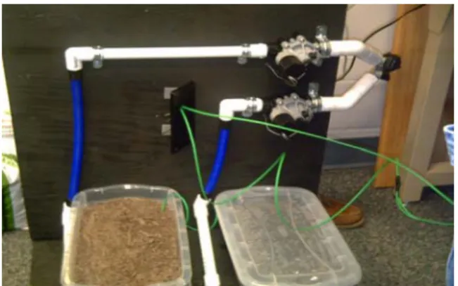
The cost of foundation repair is exponentially more expensive when compared to the cost of an automatic foundation watering system. ACCF employs moisture sensors which detect the moisture level for each section of the soil underneath the foundation of a building. The areas with a lower concentration of moisture will get watered more and vice versa. The system will be turned off automatically during rainy season when the moisture levels increase beyond a certain point. The prototype of the ACCF is shown in Figure 1.
Figure 1. ACCF Prototype
The block diagram of the system is shown in Figure 2. Only two watering areas have been used to implement the prototype but the system can be extended to any number of watering zones as per the size of the foundation and structure. The system will detect the level of moisture in each zone the ACCF is responsible for and compares these readings against one another. Based on this data, ACCF will determine the necessary watering time to bring the moisture levels in line with each other. Incorporation of moisture sensors and independent watering zones in the ACCF allows for control of shrinking and swelling of each area around a structure. Moisture is maintained evenly on all sides of the foundation creating a situation that while the foundation is still rising and falling with
Figure 2. ACCF System Block Diagram
the soil it is doing so without tilting thereby relieving stresses on the structure. This relief of stress on the foundation prevents cracking and even possible expulsion from the ground.
DESIGN DESCRIPTION
The ACCF can maintain even moisture content throughout the clay soils surrounding a structure using sensors to monitor soil moisture around the foundation and solenoid valves to isolate the watering zones. A schematic diagram of the system is shown in Figure 3.
A splitter pipe is attached to the water source outside the building to create the desired amount of watering zones. Solenoid valves control each outlet allowing for independent watering cycles. Hoses are attached to each solenoid and are run to each independent watering zone. Perforations in the hose begin as the hose reaches its specified zone, and water pressure is maintained by activating each solenoid individually. Figure 4 shows the Solenoid Valves and the Splitter in the prototype. The central control of the ACCF is the
Figure 3. Test Module
Figure 4. Solenoid Valves and the Splitter in the Actual ACCF Piping Solenoid Valve
Solenoid Valve
to bring moisture levels into equilibrium. In order to reach equilibrium as fast as possible if moisture content fluctuates outside the minimum or maximum range which can be set by the user, then the dry zones will be watered alone for the default time before the system continues with normal watering cycles. After soil moisture reaches equilibrium the system continues to monitor the soil while reverting to the specified default watering time for each zone unless future variance is detected. A Non-Disclosure Agreement with Irrometer Co., Inc. [3], the manufacturer of the moisture sensor, prevents additional details about the sensor from being disclosed. It suffices to say that a 5V pulse with less than 50 nA current sent from the microcontroller across the sensor for no longer than 50 ms is read back into the ADC. The value of this voltage data is higher if the soil is wet. The sensors then need to be grounded for at least thirty seconds to discharge any current after being read. In a full-scale system the grounding would last longer so damage to the sensor would be prevented.
HARDWARE DESCRIPTION
The Automated Clay Conditioning System for Foundations (ACCF) consists of several main components. The BiPOM 8051 microcontroller and two peripheral boards, two solenoid water valves with flow control [4-6], two Watermark soil moisture sensors [3], and a controller enclosure box with accompanying LED’s for user interface [7].
The BiPOM microcontroller and associate peripheral boards are packaged in a plastic box for safety and modularity purposes. On the exterior face of the box is a three LED user interface. The red LED signifies standby and the two yellow LED signify the system is watering the associated zones.
Products from BiPOM
BiPOM 8051 Microcontroller Board
The schematic diagram for the BiPOM 8051 microcontroller board is shown in Figure 5 and is considered to be the brain of the entire system. It turns on the sensors, acquires the data, and then determines watering times from said data. The microcontroller is accompanied by two peripheral boards, also made by BiPOM, each connected through the integrated expansion bus.
Figure 5. BiPOM Microcontroller Board Training Board 1 (TB1)
The TB1 board, shown in Figure 6, was selected primarily for the Analog-to-Digital Converter for sensor voltage interpretation and the associated analog inputs.
Figure 6. TB1 Board Relay-4 Reed Board
The purpose of the Relay-4 Reed board (Figure 7) is to allow the microcontroller to control the AC voltage required by the solenoid valves through its 5V DC output pins. A 5V DC pulse sent from the microcontroller is used to activate each of the 4 relays
Figure 7. Relay-4 Reed Board Layout Solenoid Valves
Solenoid Water Valves (Direct Lift)
The purpose of these valves (Figure 8) is to supply water flow to the various zones of the foundation. The solenoid valves are powered by a 24 VAC, 650 mA signal fed through and controlled by relays on the Reed-4Relay peripheral board.
Figure 8. Solenoid Connection Schematic
The valves are connected via a splitter to either a typical outdoor faucet through the use of an adapter, or may be tied directly into the water main of the building, much the same as a sprinkler system would. PVC tubing is connected to each of the valves and is run underground to the corresponding side of the house where water emitters distribute the water along its zone. The water emitters consist of length of PVC pipe with 3/16 inch holes drilled along their length.
Soil Moisture Sensors
Watermark Soil Moisture Sensors
The two soil moisture sensors (Figure 9) from Watermark [3] were selected due to their inexpensive nature, fast response time and ease of interface. The Watermark Soil Moisture Sensor (granular matrix sensor) is an indirect, calibrated method of measuring
Figure 9. Watermark Soil Moisture Sensor
soil water. It is an electrical resistance type sensor, consisting of two electrodes surrounded with a permeable barrier. The sensors are read by applying a pulse with duration between 1 to 50ms with a potential of 5 to 20V DC and no greater than 50nA of current. The sensor connects to the ADC on TB-1 peripheral board sending between 0 V and 2.5 V correlating between dry and wet.
A Non-Disclosure agreement with the manufacturer prohibits further detailed explanation of the sensor interface.
SOFTWARE DESCRIPTION
The software flowchart is as shown in Figure 10. It describes in detail, how the data from the moisture sensors is taken into the 8051 controller, averaged, compared & depending
Figure 10. Software Flowchart for Moisture Regulation
on the value of the result, the respective servo motors are turned on or turned off [8-9]. Start SENSOR 1 SENSOR 2 Get Data Get Data Average Data Average Data Average
Database DatabaseAverage
Total Avg Emergency Turn on or off Modifying default watering time Compare Average Difference Difference Soaker System 2 Start timer 1 Soaker System 1 Start timer 2 Wait till next check Turn off system 1 Turn off system 2 Time Check Time Check Turn On Servo 1 Turn On Servo 2
CONCLUSION
The prototype of ACCF using two watering zones performed successfully during the project demonstration. Certain precautions were required both in hardware as well as the software in order to ensure no damage occurred to the sensors. Initial troubles with plumbing were resolved through re-plumbing with added attention to complete seals. Potential follow-on projects which could be on the project are, further investigation into water emitter systems. Many products are out in the market for drip irrigation systems. Using such a system in place of the PVC pipe with holes would allow for more precise control of water flow and pressure regulation. Several models are available which allow for variable flow rates in addition to self cleaning features. Other potential follow-on projects could include a data logger system to allow users the ability to download and track moisture trends of the soil.
REFERENCES
[1] "Maintenance and Monitoring Program," Mr. Foundation,
http://www.foundationrepairs.com/foundation_watering.htm?src=, [Accessed July 15, 2008]
[2] "Foundations and Water," Advanced Foundation Repairs,
http://www.foundationrepairs.com/foundation_watering.htm?src=, see the FAQ section,
[Accessed July 15, 2008]
[3]
http://www.specmeters.com/Soil_Moisture/Watermark_Soil_Moisture_Sensors_and_Met er.html [Accessed July 15, 2008]
[4] http://www.BiPOM.com/documents/boards/minimax51c2.pdf [Accessed July 15, 2008]
[5] http://www.BiPOM.com/documents/peripherals/tb1.pdf[Accessed July 15, 2008]
[6] http://www.BiPOM.com/documents/peripherals/relay4.pdf[Accessed July 15, 2008]
[7] Scott MacKenzie, and Raphael Chung-Wei Phan, "The 8051 Microcontroller," 4th. Edition, Prentice-Hall, 2006.