USER GUIDE
AVR2050: BitCloud Developer Guide
Atmel MCU Wireless
Description
BitCloud® SDK provides Atmel® implementation of ZigBee® PRO stack, ZigBee Cluster Library (ZCL) and a set of reference applications for ZigBee Home Automation, ZigBee LightLink and ZigBee OEM devices.
This document describes key concepts for BitCloud stack configuration, network management, data exchange and other critical topics and is intended for use by application developers.
Features
•
BitCloud architecture overview•
Application development concepts•
Stack configuration•
Network management•
Data exchange description•
Power management•
Hardware interfacesTable of Contents
1.
BitCloud Architecture ... 7
1.1 Architecture Highlights ... 7
1.2 Naming Conventions ... 8
2.
BitCloud Application Programming ... 9
2.1 Event-driven Programming ... 9
2.1.1 Request/confirm and Indication Mechanism ... 10
2.2 Task Manager, Priorities, and Preemption ... 12
2.2.1 Task Manager Implementation ... 13
2.2.2 Concurrency and Interrupts ... 14
2.3 Events Management ... 15
2.4 Memory Allocation ... 16
2.4.1 RAM Usage ... 16
2.4.2 Flash Storage ... 17
2.4.2.1 Storing Variables in Flash Instead of RAM... 17
2.4.2.2 Defining Variables Stored in Flash ... 17
2.4.2.3 Reading Variables from Flash ... 18
2.5 Other MCU Resource Usage ... 18
2.6 Application Structure ... 18
2.6.1 The Main Function ... 19
2.6.2 Application Flow Control ... 19
2.6.2.1 Application State Machine... 19
2.6.2.2 Application Task Handler ... 20
2.6.2.3 Confirmation Callbacks ... 20
2.6.2.4 Stack events and Indication Callbacks ... 21
3.
Stack Configuration Parameters ... 22
3.1 Setting ConfigServer Parameters ... 22
3.1.1 CS Parameter Read/write Functions ... 22
3.2 Parameter Persistence ... 22
4.
Network Management ... 23
4.1 Networking Overview ... 23
4.1.1 Device Type ... 23
4.1.1.1 ConfigServer Parameters Affecting the Device Type ... 24
4.1.1.2 Runtime Configuration of the Device Type ... 24
4.1.2 Device Addressing ... 24
4.1.2.1 IEEE/extended Address ... 24
4.1.2.2 Short/network Address ... 24
4.1.2.3 Stochastic vs. Static Addressing Mode ... 24
4.1.2.4 Address Conflict Resolution ... 25
4.1.3 Network Topology ... 25
4.1.3.1 Limits on the Number of Children ... 25
4.1.3.2 Neighbor Table Size ... 26
4.1.3.3 Maximum Network Depth ... 26
4.1.3.4 Differences in Losing Parents between Routers and End Devices ... 26
4.1.4 Target Network Parameters ... 26
4.1.4.1 Channel Page and Channel Mask ... 27
4.1.4.2 Network Identifiers ... 27
4.2 Basic Operations and Notifications ... 28
4.2.1 Network Start ... 28
4.2.1.1 Join Control Configuration... 28
4.2.1.2 Parameters Required for Network Start ... 29
4.2.1.3 Network Start Request and Confirm ... 30
4.2.1.4 Network Formation Algorithm ... 31
4.2.1.5 Network join Algorithm ... 32
4.2.2 Parent loss and Network Leave ... 32
4.2.2.1 Parent Loss by an End Device ... 33
4.2.2.2 Child Loss Notification ... 33
4.2.2.3 Network Leave on a ZDP Request ... 34
4.2.3 Obtaining Network Information ... 34
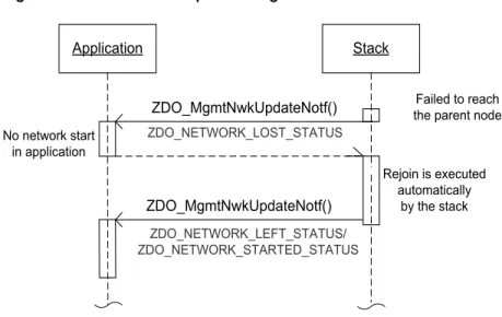
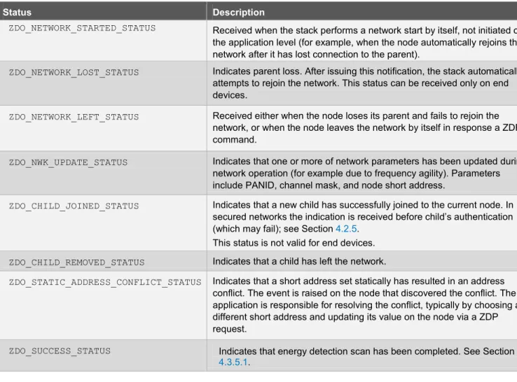
4.2.4 Network Update Notifications ... 35
4.2.5 Joining Notifications in Secured Networks ... 36
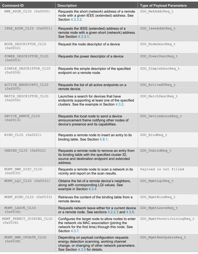
4.3 Network Management by ZigBee Device Profile Requests ... 36
4.3.1 Sending a ZDP Request ... 38
4.3.1.1 ZDP Response Timeout ... 38
4.3.1.2 Processing a ZDP Request ... 38
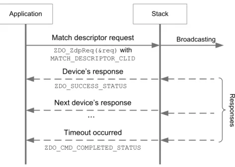
4.3.2 Service Discovery ... 39
4.3.3 Device Discovery ... 40
4.3.3.1 IEEE Address Request ... 40
4.3.3.2 Network Address Request ... 41
4.3.4 LQI Request ... 41
4.3.5 Network Update Request ... 42
4.3.5.1 Energy Detection Scan ... 43
4.3.5.2 Changing Channel ... 44
4.3.5.3 Changing Network Parameters ... 44
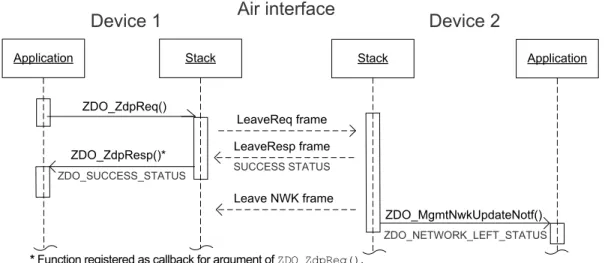
4.3.6 Network Leave Request ... 44
4.3.6.1 Leave Request to a Remote Node ... 45
4.3.6.2 Network leave on own Request ... 46
4.3.7 Permit joining Request ... 47
5.
Data Exchange ... 48
5.1 Overview ... 48
5.1.1 Application Endpoints and Data Transfer... 48
5.1.2 Clusters ... 49
5.1.2.1 ZigBee Application Profiles ... 49
5.1.3 Packet Routing ... 50
5.1.4 Delivery Mode by Destination Address ... 50
5.2 Cluster Implementation ... 51
5.3 Application Endpoint Implementation ... 51
5.3.1 General Procedure ... 51
5.3.2 Defining Instance of Cluster Attributes ... 52
5.3.3 Defining Instance of Cluster Commands ... 53
5.3.4 Filling a List of Supported Clusters ... 53
5.3.5 Setting Indication Functions for Clusters... 54
5.3.6 Filling a List of Supported Cluster IDs ... 54
5.3.7 Application Endpoint Registration ... 54
5.4 Local Attribute Maintenance ... 55
5.5 General Cluster Commands ... 56
5.5.1 Sending a General Cluster Command ... 57
5.5.1.1 Specifying Destination Address ... 57
5.5.1.2 Automatic Short Address Resolution ... 58
5.5.1.3 Processing Response Callback ... 59
5.5.2 Read/write a Remote Attribute ... 59
5.5.2.1 Payload for Read Attributes Command ... 59
5.5.2.2 Payload for Write Attributes Command ... 60
5.5.2.3 Parsing the response payload ... 61
5.5.3 Attribute Reporting ... 62
5.5.3.2 Periodic Attribute Reports ... 64
5.5.3.3 Attribute Reports on Value Change ... 64
5.5.3.4 Manual Attribute Reports ... 65
5.5.3.5 Receiving Attribute Reports ... 65
5.5.4 Discover Attributes Command ... 66
5.5.4.2 Command Parameters ... 66
5.5.4.3 Forming a Command ... 66
5.5.4.4 Processing the Response ... 67
5.5.5 Discover Attributes Extended Command ... 68
5.5.5.2 Command Parameters ... 69
5.5.6.2 Command Parameters ... 69
5.5.7 Discover Commands Generated Command ... 69
5.5.7.2 Command Parameters ... 70
5.6 Cluster-specific Commands ... 70
5.6.1 Sending a Cluster-specific Command ... 70
5.6.2 Format the Command’s Payload ... 71
5.6.3 Manufacturer-specific Commands ... 71
5.7 Broadcast and Multicast Transmissions ... 72
5.7.1 Sending a Broadcast Message ... 72
5.7.1.1 Broadcast Implementation ... 72
5.7.1.2 Broadcast Transmission Table ... 73
5.7.2 Multicast Transmission ... 73
5.7.2.1 Adding a Device to and Removing it From a Group ... 73
5.7.2.2 Sending a Data Frame to a Group ... 73
5.8 Cluster Binding ... 73
5.8.1 Implementing Local Binding ... 75
5.8.1.1 Local Binding to a Group ... 76
5.8.2 Sending Data to a Bound Target ... 76
5.9 Parent Polling Mechanism ... 77
5.9.1 Parent Polling Configuration on End Devices ... 77
5.9.2 Polling Configuration of end-device children on fully functional Devices ... 78
6.
Network and Data Security ... 80
6.1 Security Modes ... 80
6.1.1 Selecting Security Mode ... 80
6.1.1.1 Switching Security Off ... 81
6.1.2 Trust Center ... 81
6.1.3 Security Status ... 81
6.2 Standard Security Mode ... 82
6.2.1 Device Authentication during Network Join... 82
6.2.2 NWK Payload Encryption with the Network Key ... 83
6.3 Standard Security with Link Keys ... 83
6.3.1 Network Join with a Predefined Trust Center Link Key ... 83
6.3.2 Global Link Keys ... 84
6.3.3 APS Data Encryption with Link Key ... 84
6.3.3.1 Requesting the Link Key for Communication with a Remote Device ... 85
6.4 Multiple Network Keys ... 86
6.4.1 Setting Network Keys on a Node ... 86
6.4.2 Keys Distribution ... 86
6.4.2.1 Switching to a New Network Key ... 86
7.
Power Management ... 87
7.1 Sleep-when-idle ... 87
7.1.1 Going into Sleep ... 87
7.1.2 Wake up Procedure ... 88
7.1.2.1 Wake up on a Scheduled Time ... 88
7.1.2.2 Wake up on an External Hardware Interrupt ... 88
7.2 Sleep Control without Sleep-when-idle ... 90
7.3 Synchronizing Sleeping End Devices and their Parent Devices ... 90
8.
Persistent Data ... 91
8.1 PDS Configuration ... 91
8.2 Defining Files and Directories ... 91
8.2.1 File Descriptors ... 91
8.2.2 Directory Descriptors ... 92
8.3 PDS API Functions ... 93
8.4 Maintaining Stack Data in the NV Storage ... 93
9.
Hardware Control ... 96
9.1 USART Bus ... 96
9.1.1 USART Callback Mode ... 97
9.1.2 USART Polling Mode ... 98
9.1.3 CTS / RTS / DTR Management ... 99
9.2 SPI Bus ... 99
9.3 Two-wire Serial Interface Bus ... 99
9.4 ADC ... 100 9.5 GPIO Interface ... 101 9.6 External Interrupts ... 102 9.7 Timers ... 102 9.8 Drivers ... 102 9.8.1 OTAU Drivers ... 103 9.9 RF Control ... 103
Appendix A.
Extending the Cluster Library ... 104
A.1 Filling the Cluster’s Header File ... 104
A.2 Adding a New Attribute to a Cluster ... 105
A.3 Adding a New Cluster Command ... 108
Appendix B.
ZLL Overview ... 110
B.1 Architecture ... 110
B.2 Device Types ... 110
B.3 ZLLPlatform General Topics ... 111
B.3.1 Initialization ... 111
B.3.2 Finite State Machine ... 111
B.3.3 Example Transition Table ... 112
B.4 Tasks Management ... 114
B.5 Memory Allocation ... 115
B.6 Internal Flash Access ... 116
B.7 Sleeping Device Management ... 117
B.8 System Mutex Implementation ... 117
B.9 ZLL Device Configuration ... 118
B.9.1 Basic Configuration ... 118
B.9.2 Factory New State ... 118
B.9.3 Network Parameters ... 119
B.10 Touchlink Commissioning ... 119
B.10.1 Controller’s Side ... 120
B.10.2 Inter-PAN Mode ... 120
B.10.3 Scanning ... 121
B.10.4 Requesting Device Info ... 122
B.10.5 Identifying the Lighting Device ... 122
B.10.6 Joining the Network ... 123
B.10.7 Sending Add Group Request and Saving Light’s Info ... 123
B.11 Lighting Device’s Side ... 123
B.11.1 Subscribing to Events ... 124
B.12 Touchlink between Two Controllers ... 124
B.13 Setting Target Type ... 125
B.13.1 Processing Scan Indication ... 125
B.13.2 Disabling Target Type ... 126
B.14 Joining a Home Automation Network ... 126
B.15 Clusters and Addressing ... 127
B.16 Security ... 128
B.16.1 Security in Touchlink Commissioning ... 129
B.16.2 Security in Standard ZigBee Commissioning ... 129
Appendix C.
APS Data Exchange ... 130
C.1 Application Endpoint Registration ... 130
C.3 Transmission Options ... 132
C.4 Data Frame Transmission ... 132
C.4.1 Retries in Case of Failure ... 133
C.4.2 Removing Routing Table Entries if too Many Failed Attempts ... 134
C.5 Data Frame Reception ... 134
C.6 APS Fragmentation ... 135
C.6.1 The Maximum Data Frame Payload Size ... 135
C.6.2 Enabling Fragmentation in a Data Request ... 135
C.6.3 Node Parameters Affecting Fragmentation ... 136
10.
References ... 137
1.
BitCloud Architecture
1.1
Architecture Highlights
The Atmel BitCloud internal architecture follows the suggested separation of the network stack into logical layers, as found in IEEE® 802.15.4 and ZigBee. Besides the core stack containing protocol implementation, the BitCloud architecture contains additional layers implementing shared services (for example, task manager, security, and power manager) and hardware abstractions (for example, hardware abstraction layer (HAL) and board support package (BSP)). The APIs contributed by these layers are outside the scope of core stack functionality. However, these essential additions to the set of APIs significantly help reduce application complexity and simplify integration. The BitCloud API Reference manual provides detailed information on all public APIs and their use [3].
Figure 1-1. BitCloud Software Stack Architecture
The topmost of the core stack layers, APS, provides the highest level of networking-related API visible to the
application. ZDO provides a set of fully compliant ZigBee Device Object APIs, which enable main network management functionality (start, reset, formation, join). ZDO also implements ZigBee Device Profile commands, including Device Discovery and Service Discovery. The (NWK) network layer is required to provide functionality to ensure correct operation of the IEEE 802.15.4 MAC sub-layer and to provide a suitable service interface to the application layer. IEEE 802.15.4 MAC is a standard which specifies the physical layer and media access control for low-rate wireless personal area networks (LR-WPANs). The medium access control (MAC) enables the transmission of MAC frames through the use of the physical channel. Besides the data service, it offers a management interface and itself manages access to the physical channel and network beaconing.
There are three vertical service components responsible for configuration management, task management, and power down control. These services are available to the user application, and may also be utilized by lower stack layers.
•
Configuration server (CS) is used to manage the configuration parameters provided with the Atmel BitCloud stack•
Task manager is the stack scheduler that mediates the use of the MCU among internal stack components and the user application. The task manager implements a priority based cooperative scheduler specifically tuned for the multi-layer stack environment and demands of time-critical network protocols. Section 2.2 describes the task scheduler and its interface in more detail.•
Power management routines are responsible for gracefully shutting down all stack components and saving system state when preparing to sleep and restoring system state when waking up•
Hardware abstraction layer (HAL) includes a complete set of APIs for using on-module hardware resources (EEPROM, sleep, and watchdog timers) as well as the reference drivers for rapid designing and smooth integration with a range of external peripherals (IRQ, TWI, SPI, USART, and 1-wire).•
Board support package (BSP) includes a complete set of drivers for managing standard peripherals (sensors, UID chip, sliders, and buttons) placed on a development board1.2
Naming Conventions
Due to a high number of API functions exposed to the user, a simple naming convention is employed to simplify the task of getting around and understanding user applications. Here are the basic rules:
1. Each API function name is prefixed by the name of the layer where the function resides. For example, the ZDO prefix in ZDO_GetLqiRssi() function indicates that the function is implemented in ZDO layer of the stack. 2. Each API function name prefix is followed by an underscore character ( _ ) separating the prefix from the
descriptive function name.
3. The descriptive function name may have a Get or Set prefix, indicating that some parameter is returned or set in the underlying layer, respectively (for example, HAL_GetSystemTime()).
4. The descriptive function name may have a Req, Request, Ind, or Conf suffix, indicating the following: • Req and Request correspond to the asynchronous requests (see Section 2.1.1) from the user
application to the stack (for example, ZCL_CommandReq())
• Ind corresponds to the asynchronous indication of events propagated to the user application from the stack (for example, ZDO_MgmtNwkUpdateNotf())
• By convention, function names ending in Conf are user-defined callbacks for the asynchronous requests, which confirm the request's execution
5. Each structure and type name carries a _t suffix, standing for type. 6. Enumeration and macro variable names are in capital letters.
It is recommended that the application developer adhere to the aforementioned naming conventions in the user application.
2.
BitCloud Application Programming
The goal of this section is to provide clear introduction into application programming with the Atmel BitCloud stack. Every application built on top of the BitCloud stack might be considered as an additional layer or component to the components already present in the stack. This implies that the application should be designed to conform to the architecture pattern used in BitCloud components and to communicate with other components in the same manner as done inside the stack. That is why the whole section focuses on two main topics: describing request/confirm
communications between the application layer and the underlying stack layers as well as application flow organization. Most of the functions provided by BitCloud components are executed asynchronously. By calling a function, the application sends a corresponding request that specifies, among other parameters, a confirmation callback function to be executed at the request completion. The stack also informs the application about events that occurred in the network or within the device with the help of special indication functions. Event-driven programming, described in Section 2.1, is the basis for this type of communication between the application and the stack. Further details on how to apply it in the application to enable interaction with the stack components are given in Section 2.1.1.
The life cycle of the entire BitCloud environment, including BitCloud components and the application, is maintained by a task scheduler. This is the core mechanism for controlling application flow. The task scheduler determines the
sequence of task execution on different components. Actual task processing is performed by an appropriate task handler, which is a function present in each component (including the user application) that identifies actual component behavior. Section 2.2 details the task manager implementation.
In order to simplify application programming on the basis of described concepts, Section 2.6 illustrates the structure of a typical application developed on top of the BitCloud stack with code snippets. Full source code examples are provided as sample applications within the BitCloud SDK. They are intended to demonstrate all major BitCloud functionalities and serve as starting points in developing custom applications, dramatically reducing the time for creating application prototypes. Nevertheless, an application developer should understand the concepts behind existing source code to recognize the logic quickly and be able to extend it correctly.
2.1
Event-driven Programming
Event-driven systems are a common programming paradigm for small footprint, embedded systems with significant memory constraints and little room for the overhead of a full operating system. Event-driven or event-based
programming refers to programming style and architectural organization that pair each invocation of an API function with an asynchronous notification (and result of the operation) of the function completion. The notification is delivered through a callback associated with the initial request. Programmatically, the user application provides the underlying layers with a function pointer, which the layers below call after the request is serviced.
Figure 2-1. Synchronous vs. Asynchronous API Calls ZDO APL ZDO_StartNetworkConf ZDO_StartNetworkReq() ZDO_GetLqiRssi APL ZDO
In a fully event-driven system, all user code executes in a callback either a priori known to the system or registered with the stack by the user application. Thus, the user application runs entirely in stack-invoked callbacks.
2.1.1 Request/confirm and Indication Mechanism
All applications based on the Atmel BitCloud SDK require in an event-driven or event-based programming style. In fact, all internal stack interfaces are also defined in terms of forward calls and corresponding callbacks. Each layer defines a number of callbacks for the lower layers to invoke, and, in turn, invokes callback functions defined by higher levels. Each layer is also equipped with a dedicated callback called the task handler, which is responsible for executing main layer-specific logic. APL_TaskHandler() is the reserved callback name known by the stack as the application task handler. Invocation of APL_TaskHandler() is discussed in Section 2.2.1.
The request/confirm mechanism is a particular instance of an event-driven programming model. Simply put, a request is an asynchronous call to the underlying stack to perform some action on behalf of the user application; a confirm is the callback that executes when that action has completed and the result of that action is available.
For example, consider a ZDO_StartNetworkReq(ZDO_StartNetworkReq_t *req) function call, which requests the ZDO layer to start the network. The argument is a pointer to the structure of type ZDO_StartNetworkReq_t
defined in zdo.h file as follows: typedef struct {
ZDO_StartNetworkConf_t confParams;
void (*ZDO_StartNetworkConf)(ZDO_StartNetworkConf_t *conf); } ZDO_StartNetworkReq_t;
The first field (confParams) is a structure used to store the stack’s response (in this case, actual network parameters) to the request. The last field (ZDO_StartNetworkConf) is a pointer to a callback function. This is how most of the other request parameters structures are designed. The ZDO_StartNetworkReq() request is paired up with a user-defined callback function with the following signature:
//Callback for the start network request,the body of the function //shall be also present in the application
static void ZDO_StartNetworkConf(ZDO_StartNetworkConf_t *confirmInfo);
The actual callback name can be different from ZDO_StartNetworkConf, although it follows the naming convention used by the stack and is a good practice to follow as well. An actual request is preceded by an assignment to the callback pointer as follows:
static ZDO_StartNetworkReq_t networkParams; //global variable ...
//When network start should be requested //set network parameters
networkParams.channelMask = APP_CHANNEL_MASK;
networkParams.extPANId = APP_COORD_UID; // Ignored for Coordinator networkParams.ZDO_StartNetworkConf = ZDO_StartNetworkConf;
ZDO_StartNetworkReq(&networkParams); ...
The example illustrates a particular instance of using a request/confirm mechanism but all others uses follow the same approach.
Note that a request function receives as an argument a pointer to a parameter structure, which should be defined before the function call. The argument received with the confirmation callback points exactly to the confirmation parameters contained inside the request instance (networkParams.confParams in the example above). Therefore, a variable for request parameters must be defined globally. Another important requirement is that the confirmation function may not use the global variable for request parameters. Instead, it must operate with the pointer given as an argument (confirmInfo).
Whether or not an operation completed successfully can be observed through the status field contained in the confirmation parameters. If the operation fails, the status indicates the reason for it. The type of the status field is generally the same for all confirmation functions in a given stack component.
Caution: Requests from higher layers may return status codes from lower layers. For example, a ZDO request may return status codes from NWK or MAC layers. The status code of the lower layer is always issued by the lower layer itself, although it may be redefined on the higher layer’s header files. If the status code returned by a request is not found in header files of the layer that was used to send the request, search in header files of the lower layers (particularly, in the nwkCommon.h and macCommon.h files). Consider the following example with ZDO_StartNetworkConf(), provided appState is a global variable used to store application state:
//Implementation of the callback for the start network request
static void ZDO_StartNetworkConf(ZDO_StartNetworkConf_t *confirmInfo) { if (ZDO_SUCCESS_STATUS == confirmInfo->status) { appState = APP_IN_NETWORK_STATE; ... } }
For some operations, request execution takes a considerable amount of time and a confirmation function can be called minutes after the request was issued. During this time, the application may need to issue another request of the same type. But this should be done carefully because the application cannot use the same global variable for request parameters since it is going to be used by the first request for confirmation. Instead, the application needs to allocate another structure for request parameters. Otherwise, it has to postpone the second request until the first request is completed.
Note that the need to decouple the request from the response is especially important when the request can take an unspecified amount of time. For instance, when requesting the stack to start the network, the underlying layers may perform an energy detecting scan, which takes significantly longer than we are willing to block for. Sections 2.2.2 and 2.3 outline the reasons why prolonged blocking calls are not acceptable. Some system calls, especially those with predictable execution times, are synchronous. Calls from one user-defined function to another are synchronous. Apart from request/confirm pairs, there are cases when the application needs to be notified of an external event that is not a reply to any specific request. For this, there are a number of user-defined callbacks with fixed names that are invoked by the stack asynchronously. These include events indicating loss of network or readiness of the underlying stack to sleep, or notifying that the system is now awake. For the list of indication callbacks that shall be implemented on the application level, refer to Section 2.3 and Section 2.6.2.4.
System rule 1: BitCloud application should be organized as a set of callbacks that are executed on completion of API requests to the underlying layer.
System rule 2: BitCloud application is responsible for declaring callbacks to handle unsolicited system events of interest.
2.2
Task Manager, Priorities, and Preemption
A major aspect of application development is managing the control flow and ensuring that different parts of the application do not interfere with each other's execution. In non-embedded applications, mediation of access to system resources is typically managed by the operating system, which ensures, for instance, that every application receives its fair share of system resources. Because multiple concurrent applications can coexist in the same system (also known as multitasking), commodity operating system cores such as Windows® are typically very complex in comparison to single-task systems like the Atmel BitCloud stack. In BitCloud context, there is a single application running on top of the stack, and thus most of the contention for system resources happens not among concurrent applications but between the single application and the underlying stack. Both the stack and the application must execute their code on the same MCU.
In contrast to preemptive operating systems, which are better suited to handle multiple applications, but require significant overhead themselves, cooperative multitasking systems are low in overhead, but require, not surprisingly, cooperation of the application and the stack. Preemptive operating systems time slice among different applications (multiplexing them transparently on one CPU) so that application developers can have the illusion that their application has the exclusive control of the CPU. An application running in a cooperative multitasking system must be actively be aware of the need to yield the resources that it uses (primarily, the processor) to the underlying stack. Another benefit of the cooperative system is that only one stack is used, which saves a considerable amount of data memory.
Returning to the example with user callbacks, if the ZDO_StartNetworkConf() callback takes too long to execute, the rest of the stack will be effectively blocked waiting for the callback to return control to the underlying layer. Note that callbacks run under the priority of the invoking layer, and so ZDO_StartNetworkConf() runs at the ZDO priority level. Users should exercise caution when executing long sequences of instructions, including instructions in nested function calls, in the scope of a callback invoked from another layer.
System rule 3: All user callbacks should be executed in 10ms or less.
The maximum execution time specified in System rule 3 refers to the actual execution time of the callback code, rather than the waiting time for the response. For some requests, a response may be issued minutes after the request is sent.
System rule 4: Callbacks run at the priority level of the invoking layer.
The strategy for callbacks executing longer than 10ms is to defer execution. Deferred execution is a strategy for breaking up the execution context between the callback and the layer's task handler by using the task manager API. The way deferred execution is achieved is by preserving the current application state and posting a task to the task queue as follows:
SYS_PostTask(APL_TASK_ID);
Task posting operation is synchronous, and the effect of the call is to notify the scheduler that the posting layer has a deferred task to execute. For the user application, the posting layer is always identified by APL_TASK_ID. Posting a task results in a deferred call to the application task handler, APL_TaskHandler(), which, unlike other callbacks, runs at the application's priority level. In other words, the application task handler runs only after all higher priority tasks have completed. This permits longer execution time in a task handler context versus a callback context.
System rule 5: The application task handler runs only after all tasks of higher priority have completed. System rule 6: The application task handler should execute in 50ms or less.
Additional task IDs of interest are HAL_TASK_ID and BSP_TASK_ID, which refer to tasks belonging to the hardware abstraction layer or board support package, respectively. When a user application involves modifications to the HAL or BSP layers, the deferred execution of HAL and BSP callbacks should utilize those layers' task IDs when posting.
2.2.1 Task Manager Implementation
As it was described above, the stack executes in a single thread, and the execution context switches between separate actions or tasks. A special internal mechanism usually referred to as the task manager or simply the scheduler, controls the execution flow and chooses the next task handler to be called. A task handler operates in the scope of a particular stack component performing tasks associated with this component. At the code level, each task handler is represented by a special function named <Component>_TaskHandler() where Component represents the name of a layer (for example, APL, APS, NWK, HAL, etc.). Note that the source code for some component task handlers is hidden inside the Atmel BitCloud library. Changing any task handlers that are exposed in the source code, should be done with extreme care and with full awareness of why it is needed.
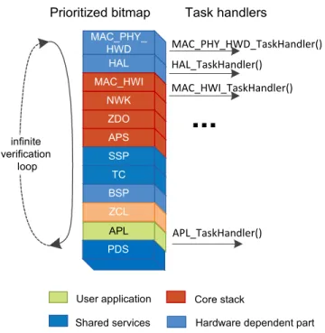
While processing, the task manager determines which layers have tasks that need to be processed and calls the respective task handlers one after another. The existence of tasks is indicated to the scheduler by special bits, which are set by calling the SYS_PostTask() function with a corresponding layer’s task id as an argument. For example, to request execution of a HAL task handler, call SYS_PostTask(HAL_TASK_ID). The task manager chooses the next task handler according to the layer’s priority. The highest priority is owned by a combined MAC-PHY-HWD layer provided with a single task handler. An application layer has the lowest priority, and so APL_TaskHandler() executes only when there are no uncompleted tasks on the other layers. Note that APL_TaskHandler() must be implemented in the application code. Figure 2-1 illustrates the task management process.
The operation of the task manager is maintained by an infinite loop residing in the main() function’s body which is available in application code (for more details see Section 2.6.1). Its core structure is following: main() starts with a call to the SYS_Init() function, which performs device initialization, and then enters an infinite loop where each iteration includes a call to the SYS_RunTask() function, thus telling the task manager to continue priority-based task execution.
Figure 2-2. Control Flow Inside the Stack
Hardware dependent part Core stack User application Shared services MAC_PHY_ HWD HAL MAC_HWI NWK ZDO APS SSP TC BSP ZCL APL Prioritized bitmap infinite verification loop Task handlers MAC_PHY_HWD_TaskHandler() HAL_TaskHandler() MAC_HWI_TaskHandler() APL_TaskHandler()
...
ZigBee Cluster Library
For additional information on task handling in ZigBee Light Link applications see Sections B.3.2 and B.4.
2.2.2 Concurrency and Interrupts
Concurrency refers to several independent threads of control executing at the same time. In preemptive systems with time slicing and multiple threads of control, the execution of one function may be interrupted by the system scheduler at an arbitrary point, giving control to another thread of execution that could potentially execute a different function of the same application. Because of the unpredictability of interruptions and the fact that the two functions may share data, the application developer must ensure atomic access to all shared data.
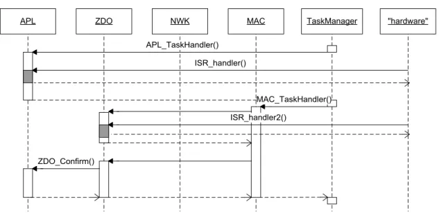
As discussed previously, a single thread of control is shared between the application and the stack in Atmel BitCloud applications. By running a task in a given layer of the stack, the thread acquires a certain priority, but its identity does not change; it simply executes a sequence of non-interleaved functions from different layers of the stack and the application. Thus the application control flow can be only in one user-defined callback at any given time. In the general case, the execution of multiple callbacks cannot be interleaved; each callback executes as an atomic code block. Figure 2-3. Normal and Interrupt Control Flow in the Stack
APL ZDO NWK MAC TaskManager "hardware"
ISR_handler()
ISR_handler2() APL_TaskHandler()
MAC_TaskHandler()
ZDO_Confirm()
Even though time slicing is not an issue, there is a special condition where another concurrent thread of control may emerge. This happens due to hardware interrupts, which can interrupt execution at an arbitrary point in time (the main thread of control may be either in the stack code or the application code when this happens) to handle a physical event from an MCU's peripheral device (for example, USART or SPI channel). This is analogous to handling hardware interrupts in any other system.
Figure 2-3illustrates an example interaction between the application, the stack, the task manager, and the hardware interrupts. Initially, the task handler processes an application task by invoking APL_TaskHandler(). While the application-level task handler is running, it is interrupted by a hardware event (shown in gray). A function that executes on a hardware interrupt is called an interrupt service routine or interrupt handler. After the interrupt handler completes, control is returned to the application task handler. Once the task handler finishes, control is returned to the task manager, which selects a MAC layer task to run next. While the MAC_TaskHandler() is running, it invokes a confirm callback in the ZDO layer, and this callback is, in turn, interrupted by another hardware interrupt. Note also that the MAC task handler invokes another ZDO callback, which invokes another callback registered by the application. Thus, the application callback executes as if it had the priority of the MAC layer or MAC_TASK_ID.
A BitCloud application may register an interrupt service routine that will be executed upon a hardware interrupt. Typically this is done by handling additional peripheral devices whose hardware drivers are not part of the standard SDK delivery and are instead added by the user. The call to add a user-defined interrupt handler is:
HAL_RegisterIrq(uint8_t irqNumber, HAL_irqMode_t irqMode, void(*)(void) f);
irqNumber is an identifier corresponding to one of the available hardware IRQ lines, irqMode specifies when the hardware interrupts are to be triggered, and f is a user-defined callback function which is the interrupt handler. Naturally, the execution of an interrupt handler may be arbitrarily interleaved with the execution of another application callback. If the interrupt handler accesses global state data also accessed by any of the application callbacks, then access to that shared state data must be made atomic. Failure to provide atomic access can lead to data races; that is, non-deterministic code interleaving, which will surely result in incorrect application behavior.
Atomic access is ensured by framing each individual access site with atomic macros ATOMIC_SECTION_ENTER and
ATOMIC_SECTION_LEAVE. These macros start and end what is called a critical section, a block of code that is
uninterruptible. The macros operate by turning off the hardware interrupts. The critical sections must be kept as short as possible to reduce the amount of time hardware interrupts are masked. On Atmel microcontrollers, flags are used, and so interrupts arriving during the masking will be saved.
System rule 7: Critical sections should not exceed 50µs in duration.
2.3
Events Management
The stack uses the events mechanism to notify stack components and the application of various significant events happening with the device such as network start or loss and address conflict. Events are used in the stack’s internal communications and are also available to the application.
The list of events used in the stack is defined in the \Components\SystemEnvironment\include\sysEvents.h
file as BcEvents_t enumeration. An event is raised when the SYS_PostEvent() function is called with the event’s ID and event’s data (or NULL if no data is provided) specified in the argument. Raising an event causes the stack to call all handler functions subscribed to that event one-by-one. A handler is added to an event via the
SYS_SubscribeToEvent() function.
The user can create its own events by adding new event IDs into the BcEvents_t enumeration. The user’s event can then be raised as any other events via the SYS_PostEvent() function. The user can provide a pointer to any piece of data as the event’s data, converted to the SYS_EventData_t type. A subscriber function will receive this pointer in its
data argument.
The application can subscribe to any of the events defined in the BcEvents_t enumeration. To subscribe to an event the application needs a callback function to process the event, defined in the following way:
void eventCallback(SYS_EventId_t eventId, SYS_EventData_t data) {
... }
And an event receiver variable tied to the callback function: //Defined globally
SYS_EventReceiver_t eventReceiver = { .func = eventCallback };
Note that the same event receiver (and the same callback function) may be used to subscribe to several events. To differentiate between events the callback function should use the eventId argument.
The application can then subscribe to an event, for example, the child joined event, calling the
SYS_SubscribeToEvent() function somewhere in the application.
SYS_SubscribeToEvent(BC_EVENT_CHILD_JOINED, &eventReceiver);
The event will be raised when the stack discovers that a new child has joined. The callback function may process the event in the following way:
void eventCallback(SYS_EventId_t eventId, SYS_EventData_t data) {
//Cast event’s data to the appropriate type ChildInfo_t *info = (ChildInfo_t *)data;
//Access child node’s info via data->shortAddr or data->extAddr ...
}
2.4
Memory Allocation
2.4.1 RAM Usage
RAM is a critical system resource used by the Atmel BitCloud stack to store run-time parameters like neighbor tables, routing tables, children tables, etc. As sometimes required by the stack, the values of certain RAM parameters are stored in the internal Flash so that their values can be restored after hardware reset. The call stack also resides in RAM, and is shared by the BitCloud stack and the user application. To conserve RAM, the user must refrain from the use of recursive functions, functions taking many parameters, functions which declare large local variables and arrays, or functions that pass large parameters on the stack.
System rule 8: Whole structures should never be passed on the stack; that is, used as function arguments. Use structure pointers instead.
System rule 9: Global variables should be used in place of local variables, where possible.
User-defined callbacks already ensure that structures are passed by pointer. The user must verify that the same is true for local user-defined functions taking structure type arguments.
System rule 10: The user application must not use recursive functions. It is recommended that the maximum possible depth of nested function calls invoked from a user-defined callback be limited to 10, each function having no more than two pointer parameters each.
Most C programmers are familiar with C library functions such as malloc(), calloc(), and realloc(), which are used to allocate a block of RAM at run time. The use of these functions is highly not recommended, even though they may be accessible from the C library linked with the stack and applications.
System rule 11: Dynamic memory allocation is not supported. The user must refrain from using standard
Overall, the RAM demands of the BitCloud stack must be reconciled with that of the user application. The amount of RAM used by the stack data is to some extent a user-configurable value that is impacted by the value of ConfigServer parameters (see Chapter 3).
2.4.2 Flash Storage
Another critical system resource is flash memory.
The embedded microcontroller uses the flash memory mainly to store program code. The user has little control on the flash, as much space consumed by the underlying BitCloud stack. Since the stack libraries are delivered as binary object files, at link time (part of the application building process) the linker ensures that mutual dependencies are satisfied; that is, that the API calls used by the application are present in the resulting image, and that the user callbacks invoked by the stack are present in the user application. The linking process does not significantly alter the amount of flash consumed by the libraries.
Additionally Persistent Data Server uses internal flash memory to store network and application parameters as described in Chapter 8.
2.4.2.1 Storing Variables in Flash Instead of RAM
To reduce RAM consumption, an application can place global or static variables holding constant data into Flash memory instead of RAM. When the application needs such variable it can easily read its value from Flash to a temporary RAM variable. For example, this may be applied to char strings or tables of function pointers.
2.4.2.2 Defining Variables Stored in Flash
To place a variable in Flash memory instead of RAM use the PROGMEM_DECLARE() macro function when defining the variable. Put the variable’s definition in brackets. Depending on the platform, the macro adds necessary compiler directives or simply const to the definition. The following example shows how to store a char string in Flash:
PROGMEM_DECLARE(char NAME_WPANID[]) = "+WPANID";
It is possible to apply the macro to the whole definition of a structure, using typedef, like in the following example from the stack: typedef PROGMEM_DECLARE(struct { ClusterId_t id; ZCL_ClusterOptions_t options; uint8_t attributesAmount; ... //other fields })ZCL_ClusterPartFlash_t;
A type defined this way can be used as a usual one to define a variable. A pointer of this type can be used as a field in common RAM structures.
//The structure to be stored in RAM typedef struct
{
ZCL_ClusterPartFlash_t *partFlashAddr; //A pointer to Flash memory ZCL_ClusterPartRam_t *partRamAddr;
bool needSynchronize; } zclClusterImage_t;
To put a function pointer to Flash, first, define a type for the function pointer. Then put this type’s name in the
PROGMEM_DECLARE() macro and apply typedef to it to define the type for storing in Flash. Finally, define and initialize a variable. The following example illustrates the described approach:
//Define the function pointer type
typedef bool (* CommandIndHandler_t)(const CommandInd_t *const commandInd); //Define the type for storing in Flash
typedef PROGMEM_DECLARE(CommandIndHandler_t) FlashCommandIndHandler_t; //Define the function which pointer will be put to Flash
bool sampleInd(const CommandInd_t *const commandInd) {
... }
//Define a table of function pointers
static const FlashCommandIndHandler_t commandIndHandlers[] = {
[0] = sampleInd, [1] = anotherInd, ...
}
2.4.2.3 Reading Variables from Flash
A variable stored in Flash cannot be used as a usual variable stored in RAM. To access the value of such variable, the application should read it via the memcpy_P() function (in most cases it is a define for the standard memcpy()
function). In the argument, provide address in RAM where to put the variable’s value, address in Flash from which to read the value, and the size. See an example below.
//Define a char array placed in Flash
PROGMEM_DECLARE(char messageInFlash[]) = "Example string"; ...
//The following code is inside some function //Define a buffer in RAM
char messageBuffer[15];
//Copy a value from Flash to the buffer in RAM memcpy_P(messageBuffer, messageInFlash, 15);
2.5
Other MCU Resource Usage
MCU hardware resources include microcontroller peripherals, buses, timers, IRQ lines, I/O registers, etc. Since many of these interfaces have corresponding APIs in the hardware abstraction layer (HAL), the user is encouraged to use the high-level APIs instead of the low-level register interfaces to ensure that the resource usage does not overlap with that of the stack. The hardware resources reserved for internal use by the stack are listed per supported platforms in [2].
System rule 12: Hardware resources reserved for use by the stack must not be accessed by the application code.
2.6
Application Structure
An Atmel BitCloud application differs significantly in its organization from a typical non-embedded C program. The following sections describe the most important code blocks that constitute a typical BitCloud application, with source code examples for each part. The complete source code can be found in the sample application projects provided with the SDK.
2.6.1 The Main Function
Every application contains a main function, which is, as usual, the starting point of the application. Typical main function is presented below. int main(void) { SYS_SysInit(); for (;;) { SYS_RunTask(); } }
A developer can add additional code into the body of the function, but the main function should always follow the structure provided: first, the SYS_SysInit() function is invoked to initialize the stack, then the SYS_RunTask()
function is called in the infinite loop to pass control to the task manager. The task manager begins invoking layers’ task handlers in order of priority (from highest to lowest), eventually invoking the application task handler. Following the initial call to the application task handler, the control flow passes between the stack and the callbacks, as shown in Figure 2-1.
2.6.2 Application Flow Control
There are three ways how application code can obtain execution control:
1. Through the task handler, following a SYS_PostTask() invocation as described in Section 2.6.2.1.
2. Through confirm callbacks invoked by underlying stack layers on request completion as indicated in Section 2.6.2.3.
3. Through asynchronous event notifications invoked by the stack as described in Section 2.6.2.4.
2.6.2.1 Application State Machine
This sub-Section describes a programming template shared by all reference applications provided with the BitCloud SDK. However developers are free to modify it to adjust for the needs of a customized application.
Following the task management implementation in BitCloud (see Section 2.2.1) application maintains global state data. The state is represented by variables for device role-dependent sub-states, various network parameters, sensor state, etc.
Developers are recommended to implement their application as a state machine. Following this abstraction, the application’s life cycle is divided into a finite number of states. Each state implies specific application logic, which is inserted by the application developer. The representation of this concept in code is given by a set of global variables that constitute the state data which is shared between the callbacks and the application task handler.
For example, consider that the global state is represented by a single variable, appState, of type AppState_t, which is defined as custom enumerated type in the application code, and has a set of predefined values for different
application states such as APP_IN_NETWORK_STATE, APP_INITING_STATE, etc. The definition of the state variable might be given in the global scope as follows:
AppState_t appState = APP_INITING_STATE;
Processing a state change requires setting of the appState variable to a target state and posting a task to the task manager via SYS_PostTask(APL_TASK_ID) function. This results eventually in calling the application task handler function (APL_TaskHandler())which utilizes value of appState variable to switch to the code that has to be executed for the particular state as described in Section 2.6.2.2.
Following the state machine architecture described above helps conform to System rules that require all callbacks and task handlers to be executed in certain time duration (as given in Section 2.2). A good practice to ensure that such system rules are followed is to split long callback or tasks executions by changing the application state, posting
application task and continue processing from the application task handler. This will guarantee that task manager will be able to handle pending stack tasks as well within require time limits. An example of such use is given in Section 2.6.2.3. Approach described above can be a basis for extending the state machine. For example by creating additional sub-state machines that can be implemented within each global application sub-state.
For additional information on task handling in ZigBee Light Link applications see Sections B.4 and B.3.2.
2.6.2.2 Application Task Handler
Every application implements a single application task handler function - APL_TaskHandler() to execute pending application tasks.
Upon device power-up/reset APL_TaskHandler() is called automatically after stack is fully initialized and is ready for use. After that it is application’s responsibility to maintain application state machine and post application tasks using
SYS_PostTask(APL_TASK_ID) function, to ensure that application tasks get processed in the
APL_TaskHandler() as described in Section 2.6.2.1.
The code for APL_TaskHandler() in the application might look like this: void APL_TaskHandler() { switch (appState) { case APP_IN_NETWORK_STATE: ... break;
case APP_INITING_STATE: //node has initial state ... break; case APP_STARTING_NETWORK_STATE: ... break; } }
For additional information on task handling in ZigBee Light Link applications see Sections B.4 and B.3.2.
2.6.2.3 Confirmation Callbacks
Every application defines a number of confirmation callback functions contributing code that executes when an asynchronous request to the underlying layer is serviced. For example, a typical application might request a network start. To make such request, the application first defines a global variable to hold the request data:
ZDO_StartNetworkReq_t startNetworkReq; // global variable After that, in an arbitrary point of the application, there should be the following code:
startNetworkReq.ZDO_StartNetworkConf = ZDO_StartNetworkConf; ZDO_StartNetworkReq(&startNetworkReq);
Here, ZDO_StartNetworkConf is the name of the callback function that is to be invoked when the request completes. Its implementation might look like this:
static void ZDO_StartNetworkConf(ZDO_StartNetworkConf_t *confirmInfo) { ... if (ZDO_SUCCESS_STATUS == confirmInfo->status) { appState = APP_IN_NETWORK_STATE; ... SYS_PostTask(APL_TASK_ID); } }
Note the use of SYS_PostTask() scheduler function. As described in Section 2.6.2.1 it is used in the application to defer processing of a network join to the application task handler, which will process it. The ZDO_StartNetworkConf callback simply changes the global state and returns to the ZDO layer that invoked it. This style of programming is consistent with cooperative multitasking system setup, and it permits the stack to handle higher priority tasks before returning to the deferred action.
To ensure execution of a user-defined callback at a specific time HAL timer can be used (see Section9.7).
2.6.2.4 Stack events and Indication Callbacks
Every application defines a number of indication callbacks with known names that execute when an event is invoked by the stack. A number of such callbacks with predefined names must be present in every application. These callbacks are:
void ZDO_MgmtNwkUpdateNotf(ZDO_MgmtNwkUpdateNotf_t *nwkParams) void ZDO_WakeUpInd(void)
void ZDO_BindIndication(ZDO_BindInd_t *bindInd) void ZDO_UnbindIndication(ZDO_UnbindInd_t *unbindInd)
If the callback does not have to carry any logic, its body can be left empty. For example, consider the following code for ZDO_WakeUpInd(): void ZDO_WakeUpInd(void) { ... if (APP_IN_NETWORK_STATE == appState) {
appState = APP_ WOKE_UP_STATE; ...
SYS_PostTask(APL_TASK_ID); }
}
3.
Stack Configuration Parameters
The Atmel BitCloud stack provides an extensive set of configuration parameters, which determine different aspects of network and node behavior. These parameters are accessible to the application via the configuration server interface (ConfigServer, or CS for short) and commonly start with CS_ prefix.
This section gives a brief introduction to the ConfigServer interface itself, while a complete list and description of CS parameters can be found in the BitCloud Stack API Reference [3] that provides explanation of the parameter, its valid range, C-type and when a parameter value can be set.
3.1
Setting ConfigServer Parameters
CS parameters can be differentiated on when they can be set as follows:
•
Only at compilation time (such as the parameters that impact memory allocation for different buffers and table) Reference for the const table can be found in csConstTable.hfile.•
Only at time when the device is out of network (parameters that determine certain network related aspects of node behavior)•
At any timeDefinitions of all CS parameters and their default values are contained in the csDefaults.h header file inside the stack.
Caution: Changing csDefaults.h file directly is not recommended. Instead, a developer is able to overwrite the default parameter values in the application header file, configuration.h. For example, the following line in the configuration file of any sample application sets the RF output power to 3dBm: #define CS_RF_TX_POWER 3
This is the simplest method for assigning new compile-time values to CS parameters.
Management of CS parameters at run time is performed with the CS read/write functions, described in Section 3.1.1.
3.1.1 CS Parameter Read/write Functions
For the reading and writing of CS parameters at run time, ConfigServer provides two corresponding API functions: CS_ReadParameter() and CS_WriteParameter(). Both functions require the parameter ID and a pointer to the parameter’s value as arguments. The parameter ID identifies the CS parameter the function is applied to and is constructed by adding "_ID" at the end of the CS parameter’s name.
The code below provides an example of how the application can read and write the RF output power value (given by the CS_RF_TX_POWER parameter):
int8_t new_txPwr = 3; // variable for writing new value int8_t curr_txPwr; // variable for reading current value CS_ReadParameter(CS_RF_TX_POWER_ID, &curr_txPwr);
CS_WriteParameter(CS_RF_TX_POWER_ID, &new_txPwr);
3.2
Parameter Persistence
Many ConfigServer parameters are defined as persistent items in csPersistentMem.c file and application can use those items or add own and keep them persistent over power cycles and resets. For more details see Chapter 8.
4.
Network Management
As described in Section 1.1, the Atmel BitCloud architecture follows the structure of the ZigBee PRO specification [6], which allows applications to interact directly only with higher layers of the core stack. Such an approach significantly simplifies application development and guarantees that the application has no impact on the networking protocol, and, hence, the application always behaves in compliance with the ZigBee PRO specification.
This section presents basic network-related concepts and introduces major stack functions concerning network
structure and organization. Special subsections briefly describe algorithms behind common operations such as network formation, join, leave, etc., and provide source code examples to illustrate interactions between the user application and the BitCloud stack. The BitCloud stack abstracts the low-level network operations, providing the high-level API that allows the application to perform any major network action with a single request to ZDO or APS.
Appendix B provides additional information on the network management procedures specific for ZLL applications (for example touchlink).
4.1
Networking Overview
A network consists of devices that can communicate with each other even if some devices may not have a direct wireless link with all the other devices. Frame packets sent by a device are routed through other devices to the destination address, allowing transferring data over comparatively large distances. A device that is part of a network is usually called a node. ZigBee networks contain nodes of several types with different network capabilities, and all nodes present in the network can perform specific application-defined actions.
To join an existing network, a device chooses a certain other device already attached to the network and establishes connection with it, thus making it its own parent node. Since each node present in a network except one has a single parent, we can view the network as a tree. While data transmission can be processed between a child and a parent, additional transmitting links are also possible. This topic as well as other important networking concepts such as node types, node addressing, network topology, and network parameters are covered in detail in the following subsections. Implementation of basic network operations is covered by Section4.2.
Note that all ConfigServer parameters mentioned in this Section normally should not be changed if a device is already joined to a network. However, most of these parameterscan be modified after the node leaves the network. To learn when a given parameter can be safely changed, refer to BitCloud API Reference [3].
4.1.1 Device Type
ZigBee PRO specification [6] differentiates among three device types that can be present in a network: coordinator, router, and end device.
•
The main responsibility of a ZigBeecoordinator (ZC) is to form a network with desired characteristics. After network formation, other nodes may be allowed to join the network via the coordinator or routers already present in the network. The coordinator node is also able to execute data routing functionality. Due to the static short address (0x0000) associated with the coordinator, only one node of such device type is allowed in the network.•
A ZigBeerouter (ZR) is able to provide transparent forwarding of data originated on other nodes to thedestination address. A router can also serve as an originator of data. In the same way as the coordinator node, routers are able to act as network entry points for other devices, and can serve as direct parents for end device nodes.
•
A ZigBeeend device (ZED) has the least networking capabilities. It can only send and receive data frames (even broadcast and multicast frames) that are always forwarded to/from the destination via the parent node the end device is currently associated with. However, among all nodes, only end devices are able to sleep.4.1.1.1 ConfigServer Parameters Affecting the Device Type
In Atmel BitCloud applications, the device type is defined by the CS_DEVICE_TYPE parameter of the DeviceType_t type. It can be set to one of the following values: DEVICE_TYPE_COORDINATOR (or 0x00), DEVICE_TYPE_ROUTER (or 0x01) and DEVICE_TYPE_END_DEVICE (or 0x02) for coordinator, router, and end device, respectively.
Additionally, a Boolean parameter, CS_RX_ON_WHEN_IDLE, must be set to true on the coordinator and router nodes, while it must be set to false on sleeping end devices to enable indirect frame reception via poll requests, as described in Section 5.9. If this parameter is set to true on an end device, parent polling will not be applied.
4.1.1.2 Runtime Configuration of the Device Type
Since the device type is determined by ConfigServer parameters, it can be specified either at compile time or during application execution. The latter case is restricted; the application can specify the device type only when the device is out of the network. Below is a code example that configures a node as an end device:
DeviceType_t deviceType = DEVICE_TYPE_END_DEVICE; bool rxOnWhenIdle = false;
CS_WriteParameter(CS_DEVICE_TYPE_ID,&deviceType);
CS_WriteParameter(CS_RX_ON_WHEN_IDLE_ID, &rxOnWhenIdle);
4.1.2 Device Addressing 4.1.2.1 IEEE/extended Address
In accordance with the ZigBee standard [6], each device shall be uniquely identified by an extended non-zero (64-bit) address, often also called a MAC or IEEE address. In the BitCloud stack, the extended address is determined by the CS_UID parameter, and, as with any other ConfigServer parameter, it can be set as described in Section 3.1. Before the network start procedure, the application shall ensure that the extended address is assigned uniquely on every device.
Note that if at compile time CS_UID is set to 0, Atmel reference applications attempt to read the extended address value from the user signature row of the device or external EEPROM (depending on the board) using the BSP_ReadUid() function. If the board doesn’t support such mechanism then CS_UID value won’t change and it is responsibility of the user either to update BSP_ReadUid() function or implement another way of ensuring that unique CS_UID is assigned before device initiates network join procedure.
4.1.2.2 Short/network Address
When joined to a ZigBee network, each node is identified by the so-called short (16-bit) address, sometimes also referred to as the network (NWK) address, which is inserted into frame headers instead of the extended address during data exchange to reduce overhead.
In an Atmel BitCloud application, a short address can be either selected randomly by the stack (stochastic addressing) during entering the network or assigned to by the user application to a desired value (static addressing) prior to the network start procedure. It is critical to ensure that all nodes in the network use the same addressing scheme; that is, either stochastic or static addressing.
4.1.2.3 Stochastic vs. Static Addressing Mode
The Boolean CS_NWK_UNIQUE_ADDR parameter specifies whether stochastic addressing (if set to 0) or static addressing (if set to 1) is applied on the node. In the latter case, a desired short address value should be assigned by the
application to the CS_NWK_ADDR parameter. Note that static address assignment is Atmel-specific implementation, for ZigBee-compliant products only stochastic addressing mechanism shall be used.
If the static addressing scheme is used, the application shall always assign the coordinator short address to 0x0000. In the stochastic addressing scheme, this value is set on the coordinator automatically by the stack. After the network start, a device can read its own short address from the .shortAddr field in the argument of the
ZDO_StartNetworkConf() callback function registered for the network start request, as described in Section 4.2.1.3 or by reading CS_NWK_ADDR parameter.
4.1.2.4 Address Conflict Resolution
In the stochastic addressing scheme, a special address conflict resolution mechanism automatically detects and resolves situations where a randomly chosen short address appears to not be unique; that is, another node with the same address is already present in the network. After the short address is updated, the application on the
corresponding node is informed about this via the ZDO_MgmtNwkUpdateNotf() function with status
ZDO_NWK_UPDATE_STATUS (0x8E) and new short address value in the argument. In a network with the static addressing scheme, the application is responsible for resolving such conflicts. But the stack provides some assistance by calling the ZDO_MgmtNwkUpdateNotf() function with status ZDO_STATIC_ADDRESS_CONFLICT_STATUS (0x95) on the node that has detected the conflict (which can differ from the node with a conflicting address).
4.1.3 Network Topology
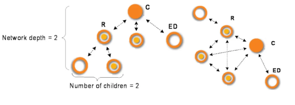
As was mentioned earlier, network topology follows a tree structure. Network construction is always started by a coordinator node, which performs network the formation procedure and sets the desired network parameters. When the formation procedure is completed, the coordinator is able to establish connections with routers and end devices. Each node joining the network connects to a certain parent node, which can be either a router or the coordinator.
Figure 4-1. Network Organization vs. Data Exchange
a. Network organization b. Available transmission links
Since a router can send data to any other router or the coordinator that it can reach, network organization (topology) can be very different from the actual communication links used to route data across the network. This is illustrated by Figure 4-1. Figure 4-1b shows the direct transmission links available in the network organized according Figure 4-1a, assuming all nodes are located within signal range of each other.
It is essential that in addition to the node parameters described in sections4.1.1 and 4.1.2 a node shall also configure topology-related parameters prior to network join. Proper node and network configuration will help achieve the desired network behavior and enhance performance.
4.1.3.1 Limits on the Number of Children
Router and coordinator nodes can limit the number of direct children that can join to them by configuring
CS_MAX_CHILDREN_AMOUNT, which defines the total maximum number of direct child nodes (routers plus end devices). The CS_MAX_CHILDREN_ROUTER_AMOUNT parameter defines the maximum number of routers among the child nodes. Thus, the difference between both parameters specifies the maximum number of end devices that can be connected to this node simultaneously, namely:
CS_MAX_CHILDREN_AMOUNT - CS_MAX_CHILDREN_ROUTER_AMOUNT Note that the following should hold true on router and coordinator nodes:
CS_NEIB_TABLE_SIZE > CS_MAX_CHILDREN_AMOUNT >= CS_MAX_CHILDREN_ROUTER_AMOUNT
4.1.3.2 Neighbor Table Size
CS_NEIB_TABLE_SIZE must be set during compilation, as its value is used for allocating memory for stack tables. For router and coordinator the neighbor table size defines the limit of possible direct children as described by formula in Section 4.1.3.1. It also has some indirect impact on routing capabilities.
Also for all nodes (including end devices), CS_NEIB_TABLE_SIZE parameter limits the maximum number of potential parents the node is able to choose from during network joining procedure.
Since routers and the coordinator continue to actively use their neighbor tables to store information about children and neighbors after the network start, its size should larger than on an end device.
4.1.3.3 Maximum Network Depth
The CS_MAX_NETWORK_DEPTH parameter specifies the maximum network depth, which is the maximum possible number of edges in a network tree from a node to the coordinator. If maximum network depth is reached on a certain router, the router will not be able to have any children, even if other parameters allow it. Additionally,
CS_MAX_NETWORK_DEPTH has impact on several timeout intervals used inside the stack (for example, the broadcast delivery timeout). Besides, CS_MAX_NETWORK_DEPTH multiplied by two bounds equals the maximum number of hops that can be made during data routing. For correct network operation, this parameter should be assigned the same value on all the nodes in the network.
4.1.3.4 Differences in Losing Parents between Routers and End Devices
If an end device loses connection to the parent, it cannot continue functioning as a normal network node. From this moment on it is out of the network, and so to be able to exchange data it must search for the network again. On the other hand, if a router’s parent becomes inaccessible, as would happen if the coordinator to which the router has connected switches off, the router still operates as a normal network device, receiving and routing data frames. Moreover, a router is not considered a child by its parent after the parent receives the first link status frame from the router. And so from this point of view, a node of the router type can be considered as not having a parent. The device to which it connects on the network serves only as an entry point that provides the necessary network information. More information on the subject of parent loss and network leave can be found in Section4.2.2.
4.1.4 Target Network Parameters
Prior to initiating a network start procedure, the node is responsible for setting parameters that characterize either the network it wishes to form (for a coordinator) or the network it wishes to join (for routers and end devices). These parameters are:
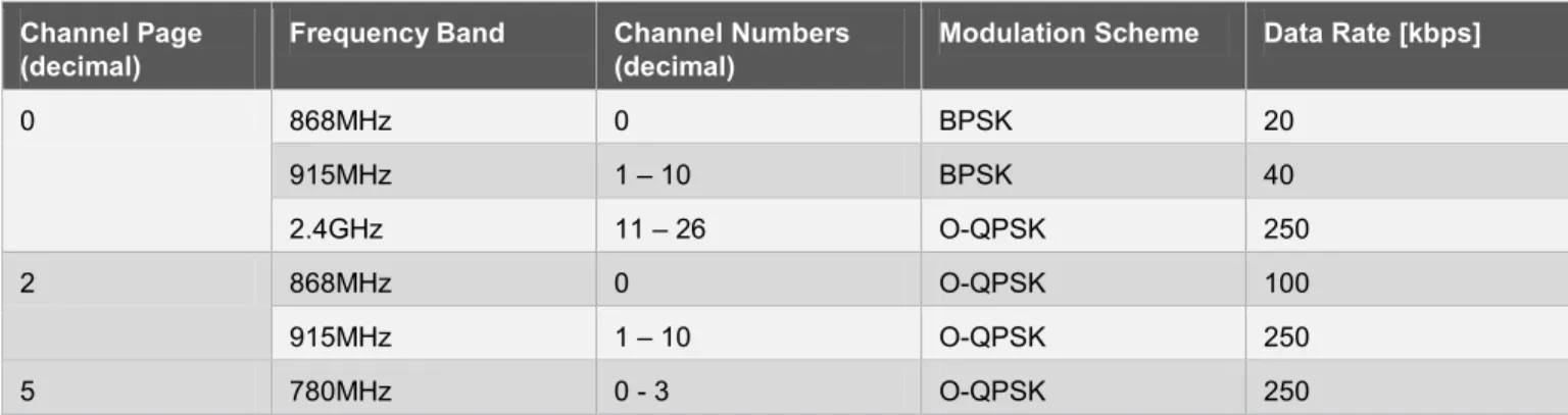
1. Supported modulation scheme, the so called channel page (CS_CHANNEL_PAGE).
2. Supported frequency channels, specified via a 32-bit channel mask (CS_CHANNEL_MASK). 3. 64-bit extended PAN ID (CS_EXT_PANID).
4. Security parameters (see Chapter6).
In parenthesis are shown the parameter names in the ConfigServer (CS) component that are used by the Atmel BitCloud application in order to assign desired values to corresponding network parameters, as described in Chapter 3.