Version 1
CDPM
Setup and
Installation Guide
CDPM DIGITAL PAGING MICROPHONE
Cloud Electronics Limited
Copyright Cloud Electronics Limited 2005
CLOUD ELECTRONICS LIMITED
CDPM Setup and Installation Guide
©Cloud Electronics Limited
140 Staniforth Road • Sheffield S9 3HF • England Phone +44 (0)114 244 7051 • Fax +44 (0)114 242 5462 E-mail [email protected] • WebSite www.cloud.co.uk
CLOUD ELECTRONICS LIMITED
1 Safety
. . . .1
2 General . . . .1
3 How to use the CDPM . . . .1
3.1 Announcing to a selection of zones . . . .1
3.2 Announcing to all zones . . . .1
3.3 Setting up a group . . . .1
3.4 Announcing to a preset group . . . .2
3.5 Announcement Interruption . . . .2
4 Power Requirements . . . .2
4.1 Using an External Adapter . . . .2
4.2 Powering from a Cloud host mixer . . . .3
5 Cables and Connections . . . .3
5.1 Connecting between CDPM microphones . . . .3
5.2 Connecting the CDPM to a mixer using RJ45 . . . .4
5.3 Connecting the CDPM to a mixer with short-to-ground contacts .4
6 Installation of the Analogue Interface . . . .5
7 Configuring the CDPM . . . .6
7.1 Power Options . . . .6
7.2 Setting the Display . . . .6
7.3 Selection Auto-Reset . . . .7
7.4 Power-on Non-Volatile Memory (NVM) reset . . . .7
7.5 Lock groups . . . .7
7.6 Priority setting . . . .7
CLOUD ELECTRONICS LIMITED
7.8 Enabling/Disabling Zone Buttons . . . .8
7.9 Terminating the Buss . . . .9
7.10 Configuring dual purpose microphone inputs on the Host Mixer 9
8 Jumper and default settings summary . . . .10
9 Scenarios . . . .11
9.1 Connecting a CDPM-4 to a 46/50 . . . .11
CLOUD ELECTRONICS LIMITED
The CDPM paging microphones operate from a low voltage supplied by either an AC adaptor or the Cloud host device to which the mic is connected; as such the unit requires little in the way of special safety precautions. However the case and gooseneck of the microphone are electrically connected to the chassis of the Cloud host device. This means that if the mains wiring to the host device and/or in the building is incorrect, the microphone could present a shock hazard. Fitting a suitable earth leakage circuit breaker (e.g. 30mA RCD type) can provide additional protection to the mains supply of the Cloud host device if required.
CDPM paging microphones interconnect using the Cloud Paging Interface. This is a custom interface based on RJ45 connectors and CAT-5 cable. It is possible to create a paging system with a total cable length of 1km. The optional analogue interface allows the CDPM system to interface with industry standard, short-to-ground paging access systems making the CDPM compatible with the Z4II, Z8II,
Matrix 4, CX263, CX163, 36/50, 46/50 and MPA-626.
The microphones feature individual zone selection, multiple zone selection, preset zone group selection, ‘TALK’ and ‘CALL ALL’ buttons, pre-announcement chime, internal chime sounder, 'BUSY' LED, configurable two-layer announcement priority system, auto zone reset after announcement and zone disable.
The different models of CDPM microphone accommodate 4, 8, 12 and 16 zones respectively. Sixteen is the maximum number of zones a single CDPM network is capable of paging. Up to 32 CDPM units may be used on one network. The different models of microphone can be mixed on a system so that there are models with differing numbers of zones. The display setting feature enables a CDPM to correspond to any consecutive group of zones on the system.
1. Depress the button(s) for the zone(s) in which the announcement is to be made. 2. The LEDs corresponding to the selection should illuminate.
3. To start announcing depress and hold the ‘TALK’ button.
4. While holding the ‘TALK’ button, zones may still be selected/deselected. 5. Once the announcement is finished, release the talk button.
NOTE: Once the talk button is released, the selection can either remain or be cleared. Internal jumper J10 is used to determine this behaviour (see section 7.3).
1. Depress and hold the ‘CALL ALL’ button.
2. All zone LEDs for enabled zones on the microphone will illuminate. 3. Make the announcement.
4. Zones may be selected/deselected during the announcement. 5. Once the announcement is finished, release the ‘CALL ALL’ button.
1. Select the zones for the group by pushing the corresponding zone button. 2. Selected zones will be indicated through the illumination of the adjacent LED. 3. Push and hold the appropriate group button until the LEDs begin to flash. 4. Release the group button.
CLOUD ELECTRONICS LIMITED
NOTE:This feature is only available if the CDPM group lock is off. See section 7.5 for details of how to set the group lock.
1. Push the appropriate group button. 2. Depress the ‘TALK’ button and hold. 3. Make the announcement.
4. Zones may be selected/deselected during the announcement. 5. Release the ‘TALK’ button.
In systems using multiple CDPM microphones, it is possible for announcements from different microphones to coincide. The system’s response to this depends on the priority settings of the microphones in question. It is not possible for two microphones on the network to make an announcement at the same time.
If an announcement is interrupted by a higher priority microphone, the initial announcement will be cut off and the interrupting announcement will take over. The interrupted CDPM will indicate this interruption by flashing the zone selection LEDs. The selection LEDs will remain lit so that the announcement may be attempted once the system is free.
If the interrupting microphone is of an equal or lower priority, then the initial announcement will be allowed to continue to its conclusion. The interrupting CDPM will flash its selected zone LEDs to indicate that the announcement cannot be made, and that the system is already in use. The zone selection on the microphone will remain so that the announcement may be attempted once the system is free.
The CDPM can derive power from either an external power supply, such as the CDPM-PSU, or from a Cloud host mixer. Only one microphone may be powered from the mixer and the power sharing with the mixer is switched off once an external power supply is connected to the microphone.
An external power supply can be connected to the CDPM through the 2.1mm coaxial power socket on the rear panel. Suitable supplies that can be used with the CDPM should be capable of providing up to 107mA current and should be in the following range; AC:9-17V, DC:12-24V. Often DC adapters have poor regulation, and some 15V supply outputs can reach as much as 17V. If in doubt, use a 12V AC adapter such as the CDPM-PSU. Polarity at the coaxial power socket is not important.
Important Note: Any DC adapter or external power supply should not have its output earthed, as this may introduce earth loops to the system. Most plug top adapters meet this criterion. The integrity of the system’s mains earth should NEVER be compromised to meet this requirement or to solve any earth loop problem.
2 V1 210605
CLOUD ELECTRONICS LIMITED
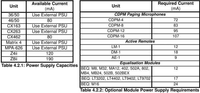
For CDPM units on the network which are to be connected to a mixer, it is possible to power the CDPM from the mixer as long as the capacity of the mixer is sufficient and the mixer has a power supply connection for paging microphones. As a general rule, a mixer cannot supply to a CDPM that has more zones than the mixer. If the mixer is supplying power to other optional modules in addition to the CDPM then the mixer may be stretched beyond its capacity. In such cases, an external adapter must be used for the CDPM. For specific details of Cloud mixer current capacities and requirements of each optional module, see tables 4.2.1 and 4.2.2 below.
There are two ways in which a CDPM can connect to power on a Cloud host mixer. The RJ45 ‘OUT’ connection on the CDPM carries power, so the last microphone in the network will obtain power from this connection if it is connected to a mixer, and no external power supply is connected to the microphone. The optional analogue interface also has a ‘PWR’ screw terminal which should be connected to the ‘+V’ connection at the Cloud host mixer. This connection requires an additional core in the access cable.
Each CDPM is fitted with two RJ45 sockets labelled ‘CAN PORTS’. These sockets are for the custom interface the CDPM microphones use to communicate. Audio is directional on this interface, and so is transmitted from the ‘OUT’ connection to the ‘IN’ connection on the next microphone or mixer in the chain. The CDPM microphone can also be connected to a mixer using the industry-standard, short-to-ground paging system when using the optional analogue interface.
Using the RJ45 connections on the rear of the CDPM, the 'OUT' port of a CDPM should be connected to the 'IN' port of the next in the chain. Connections are pin-to-pin between the two ends of the cable. The standard Cat-5 to RJ45 wiring convention is shown in table 5.1.
NOTE:The RJ45 network must be terminated at both ends. See section 7.9 of this manual to find details of how to terminate the Clouod Paging Interface buss.
3 V1 210605
Unit Required Current
(mA) CDPM Paging Microphones CDPM-4 72 CDPM-8 83 CDPM-12 95 CDPM-16 107 Active Remotes LM-1 12 DM-1 18 AE-1 9 Equalisation Modules
BEQ: M8, M32, MA12, 402, 502A, 802, MB4, MB24, 502B, 502BEX
12 BEQ: LT3202, LT4402, LT9402, LT9702 17 BEQ: M16 24
Unit Available Current
(mA)
36/50 Use External PSU
46/50 80
CX163 Use External PSU
CX263 Use External PSU
CX462 80
Matrix 4 Use External PSU
MPA-626 Use External PSU
Z4ii 120
Z8ii 190
Table 4.2.1: Power Supply Capacities
Table 4.2.2: Optional Module Power Supply Requirements
Table 5.1: RJ45 Connections RJ45 CAT-5 Pin 8 Brown/White Pin 7 White/Brown Pin 6 Green/White Pin 5 White/Blue Pin 4 Blue/White Pin 3 White/Green Pin 2 Orange/White Pin 1 White/Orange
CLOUD ELECTRONICS LIMITED
RJ45 connections between the CDPM and a mixer are pin-to-pin. The conventional core connections between Cat-5 and RJ45 plugs is shown in Table 5.2.
A network using this connection type should have a total cable length less than 1km. Where a mixer has facility for both RJ45 and access contact connection, the RJ45 connection should be used.
NOTE: Mixers will only receive audio from CDPMs that have connected ‘OUT’ towards the mixer network location. It is possible to connect a mixer at any point within the network, however an intermediate mixer will not be able to receive audio from microphones connected ‘IN’.
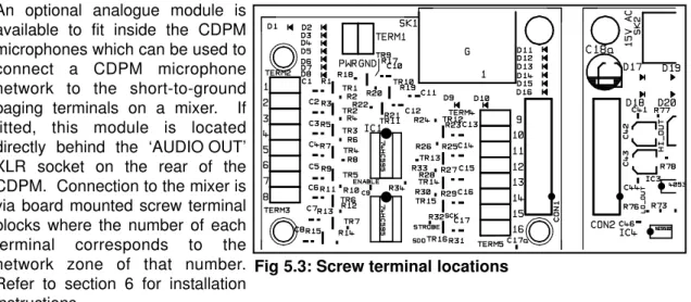
An optional analogue module is available to fit inside the CDPM microphones which can be used to connect a CDPM microphone network to the short-to-ground paging terminals on a mixer. If fitted, this module is located directly behind the ‘AUDIO OUT’ XLR socket on the rear of the CDPM. Connection to the mixer is via board mounted screw terminal blocks where the number of each terminal corresponds to the network zone of that number. Refer to section 6 for installation instructions.
There are two cables required for connection to the analogue interface:
Audio Cable: The audio cable should be a standard two-core, screened, microphone audio cable. This cable is connected to the XLR socket marked 'AUDIO OUT' on the rear panel. Connections to this XLR are pin-2 as in phase (hot), pin-3 as inverse phase (cold) and the connector shield as a ground termination
Control Cable:The control cable should contain a core for each zone to be connected to it and a core for the 'GND' connection. This cable should also be screened, but this should be separate to the 'GND' connection. If the CDPM is to be powered from the Cloud host mixer then an additional core is required on the control cable.
The control cable should be inserted through the rear panel via a cable gland fitted to the hole marked 'ANALOGUE PORT'. A suitable cable gland is provided with the analogue interface. For installation and connection details, refer to section 6 of this manual.
NOTE:Connections to this terminal should have a total cable length of less than 100m.
NOTE: Mixers will only receive audio from CDPMs that have connected ‘OUT’ towards the mixer network location. It is possible to connect a mixer at any point within the network, however an intermediate mixer will not be able to receive audio from microphones connected ‘IN’.
4 V1 210605
Fig 5.3: Screw terminal locations
Table 5.2: RJ45 Connections RJ45 CAT-5 Pin 8 Brown/White Pin 7 White/Brown Pin 6 Green/White Pin 5 White/Blue Pin 4 Blue/White Pin 3 White/Green Pin 2 Orange/White Pin 1 White/Orange
CLOUD ELECTRONICS LIMITED
5 V1 210605
An optional analogue interface is available for the CDPM which can be fitted to a CDPM to enable connection to a short-to-ground paging system. In order to install the module, the following additional hardware has been provided:
1x 5-9mm cable gland
2x black self-tapping screws for XLR fixing 4x M3 fixing screws for PCB fixing
1. Disconnect power from the microphone.
2. Free the display from the base by removing all fixing screws in the bottom and the two M3 screws on the rear panel. Keep these screws for reassembly.
3. The microphone element should be disconnected from the screw terminals and the ribbon cable at ‘CON3’ should be disconnected.
4. Remove the display metalwork.
5. Remove the blanking plate covering the two circular holes in the rear panel.
6. Fit the module such that the XLR socket fits through the hole marked ‘AUDIO OUT’ on the rear panel. 7. Fix the module to the base using the M3 fixing screws provided.
8. Fit the black self-tapping screws to the XLR socket.
9. Fit the threaded shaft of the cable gland to the hole marked ‘ANALOGUE PORT’ on the rear panel. Fix this using the sharp edged nut to provide a firm electrical contact.
10. Remove the domed nut and rubber tube from the cable gland, then thread first the domed nut then the rubber tube onto the cable.
11. Strip back the shield on the signals cable such that once the rubber tube is inserted into the threaded shaft, the cable shield will be clamped between the rubber tube and the metal of the shaft.
12. Put the cable through the threaded shaft and then insert the rubber tube. Tighten the domed nut to clamp down on the cable.
13. Connect access cores to their respective access terminals. These are located at either side of the module and are detailed in diagram 5.3. Connect the ‘0V’ mixer contact to the ‘GND’ terminal and if you are intending to power the microphone from the mixer, connect the ‘+V’ mixer contact to the ‘PWR’ terminal.
14. Connect the modules ribbon cable to the main board socket ‘CON2’.
15. Reconnect the microphone element. The red core should be connected to the ‘MIC+’ screw terminal, and the blue/black core should be connected to the ‘MIC-’ screw terminal.
16. Reconnect the display ribbon cable to ‘CON3’.
17. Fix the chassis back on to the base using the screws kept from step 2. 18. Reconnect the power.
The output of the analogue interface reflects zone selections across the entire system and is not limited by the number of zones available on the microphone it is contained within E.G. an analogue interface installed into a CDPM-4 will be able to operate over all 16 network zones if other microphones on the system require it.
The analogue interface monitors the state of its output, so can detect when the short-to-ground connections are in use by another microphone. If the short-to-ground contacts are in use, the system is assumed to be busy. When the short-to-ground contacts are busy, only high priority microphones on the CDPM network may make an announcement. This allows the short-to-ground interface to be used in networks which also use other paging equipment such as the CPM-4 and CPM-8.
Only one CDPM in a network will require the analogue interface for the whole network to be connected to a short-to-ground paging system.
CLOUD ELECTRONICS LIMITED
NOTE:Jumper settings are only checked at initialisation of the microphone, shortly after the power has been connected. In order for jumper changes to be recognised, the power will need to be disconnected and then reconnected to the microphone. See section 8 for a summary of jumper settings, their purposes and a diagram detailing their locations.
When removing jumpers we recommend that the link remain connected to one leg of the header, to prevent loss of the link.
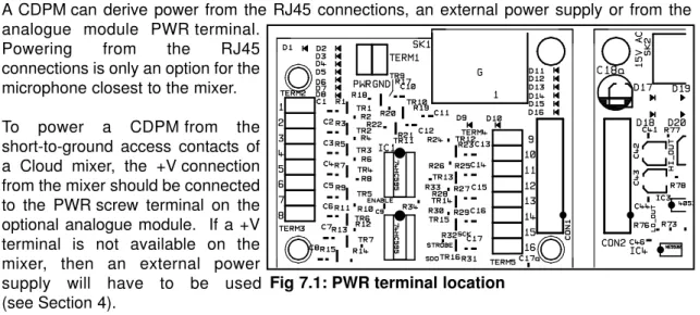
A CDPM can derive power from the RJ45 connections, an external power supply or from the analogue module PWR terminal.
Powering from the RJ45 connections is only an option for the microphone closest to the mixer. To power a CDPM from the short-to-ground access contacts of a Cloud mixer, the +V connection from the mixer should be connected to the PWR screw terminal on the optional analogue module. If a +V terminal is not available on the mixer, then an external power supply will have to be used (see Section 4).
It is possible to offset the zones a microphone is mapped to by setting the display. This is useful in situations where a CDPM is to operate over a sub-set of the available zones. Factory default is for the display to be set so that Zone 1 on the CDPM display corresponds to Zone 1 on the paging network. Jumpers J11-14 offset the display such that the displayed zone on the CDPM corresponds to the network zone which is the sum of the display and the offset. When each of these jumpers is in the ‘ON’ (linking the pins) position they will add the following amounts to the display offset:
J11 = +8 J12 = +4 J13 = +2 J14 = +1
E.G. To set a CDPM-4 to operate on zones 10-13, links should be on for J11 and J14. J12 and J13 should be unlinked. Zones 1-4 on the CDPM display will then correspond to network zones 10-13 respectively.
In any given installation, the CDPM network will support a maximum of 16 zones. If a CDPM display is set such that it accesses network zones greater than 16, these zones will wrap back around to zone 1 upwards.
E.G. If a CDPM-8 display is set to operate from zone 10 (J11 on and J14 on) then buttons 1-7 will correspond to zones 10-16 and button 8 on the microphone display will correspond to zone 1.
6 V1 210605
CLOUD ELECTRONICS LIMITED
NOTE: Setting the display only offsets the current microphone’s display, the offset does not apply to the network zones. Thus, setting the display on a microphone will not effect any other microphones on the network.
The automatic zone reset facility suits applications where the combination of selected zones varies from one announcement to the next. This facility will automatically reset all previously selected zones whenever the ‘TALK’ or ‘CALL ALL’ buttons are released or 30 seconds after the last key-press. This feature is enabled by setting jumper J10 such that the header links the two pins.
J10: Link indicates that zones should remain selected once talk button is released.
To reset the CDPM microphone to the software factory defaults (group memory empty, all zones enabled), the unit will need to be powered up with jumper J7 linking the pins. Once the reset has been performed, ensure that the header does not link the pins for subsequent power-ons. J7: Resets all groups when power is reconnected to the CDPM.
Once the groups have been set and stored in memory, linking the pins on internal jumper J9 will lock these group settings, to prevent groups being set during operation.
J9: Locks the groups.
NOTE:J7 (non-volatile memory reset) takes precedence over J9(group lock). This means that even if group lock is on when a NVM reset takes place, the group memory will be cleared.
!
There are two priority groups available for a CDPM microphone; high priority and normal priority. All units come configured to operate at normal priority and as such will operate using a 'first-come-first-serve' protocol. To make a microphone high priority, link the pins on jumper J8. J8: Link indicates that the unit is high priority
CDPMs that are on the same priority level will operate using the 'first-come-first-serve' protocol. If announcements collide between a normal priority microphone and a high priority microphone, the high priority microphone will take precedence (see section 3.5).
Microphones that are set to operate with high priority can still make an announcement if the system is busy and not held by another high priority microphone. If the system is being used in conjunction with other paging microphones which use the short-to-ground paging system, then announcement collisions could occur between the high priority CDPM microphones and the short-to-ground microphones.
CLOUD ELECTRONICS LIMITED
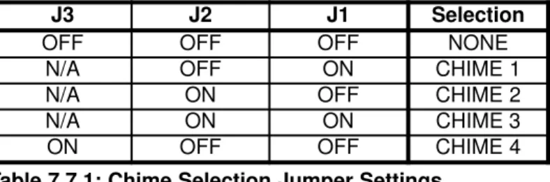
There are four chimes available to the user on a standard CDPM microphone. The selected chime will sound whenever the ‘TALK’ or ‘CALL ALL’ button is depressed, and is automatically routed to the appropriate zones. The chime level can be set by adjusting pre-set pot PR1 inside the microphone. Jumpers J1-3 select which of the four available chimes is to be used by a microphone. Setting the chime on a microphone will not effect any other microphones on the network. Possible selection positions for the chime are listed in table 7.7.1 below.
Table 7.7.1: Chime Selection Jumper Settings
To disable the chime, set internal jumper J5 to the off position and jumpers J1-3 to all be off. To disable the internal CDPM speaker, set internal jumper J6 to the off position.
J1-3: Chime 1-4 select. J5: Overall chime on or off. J6: Internal chime on or off.
To restrict the zones which a microphone can access, zones may be disabled. Zones can only be disabled when the unit has powered up after a NVM Reset (see section 7.4). To disable a sub-set of zones:
1. Power up the unit on a NVM reset (J7 linking pins). 2. Depress and hold the clear button on the unit. 3. Select the zones that you wish to disable.
4. When the selected zone lights begin to flash, the microphone has entered the Disable Group Edit mode.
5. Continue to hold the clear button and complete the selection/deselection process on the zone display buttons.
6. Release the Clear button once the selection is complete. The selected zones will then be written to memory as the Disabled Group.
7. Selected zones will remain on the display to confirm the selection (but cannot be accessed). Press Clear again to clear the display.
8. Disconnect power, then disconnect jumper J7 to prevent NVM reset on power-up
Once a zone has been disabled, it will be completely inaccessible to that CDPM (including all call and group selection operations). Note that disabling a particular zone on a microphone will not effect any of the other microphones on the network.
J3 J2 J1 Selection
OFF OFF OFF NONE
N/A OFF ON CHIME 1
N/A ON OFF CHIME 2
N/A ON ON CHIME 3
ON OFF OFF CHIME 4
8 V1 210605
The Cloud Paging Interface Buss must be correctly terminated at each end to prevent communication problems. The factory default settings for the CDPM configure the unit to terminate the buss correctly. This means that intermediate microphones (those with both an ‘IN’ and ‘OUT’ connection) will need to be reconfigured to not terminate the buss. For these microphones, internal jumper J4 should be set to the OFF position (i.e. no link between the pins).
On the 36/50, 46/50, CX263 and CX163 mixer sections, the Microphone 1 input can be used as either a general purpose microphone (default) or as a paging microphone. In order for the microphone input to be used as a paging microphone, the access contacts on the rear panel should be enabled using the appropriate jumpers. The table below shows the appropriate jumpers for each of these units, and the corresponding diagram shows the jumper location inside the unit.
36/50 Mic 1 Access Jumpers
J2 - Zone 1; J3- Zone 2; J4- Utility
46/50 Mic 1 Access Jumpers
J20- Z4; J21- Z3; J22- Z2; J23- Z1
CX263 Mic 1 Access Jumpers
J4- Zone 1; J5- Zone 2; J6- Zone 3
CX263
ACC BYP
J4-6 SETTINGS
CX163 Mic 1 Access Jumpers
J1- Zone 1; J2- Zone 2; J3- Utility
POWER CX163 ZONE 1 ZONE 2 1 2 3 4 5 6 2 ZONE STEREO AUDIO MIXER ACC BYP J1-3 SETTINGS
CLOUD ELECTRONICS LIMITED
CLOUD ELECTRONICS LIMITED
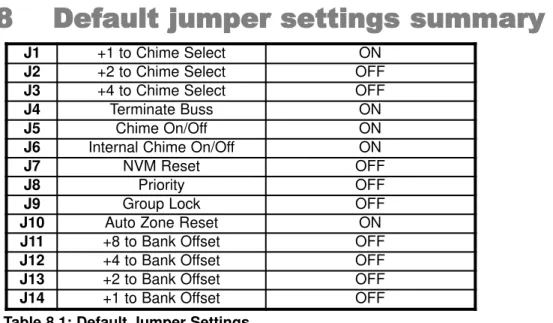
Table 8.1: Default Jumper Settings
When removing jumpers we recommend that the link remain connected to one leg of the header, to prevent loss of the link.
When making internal adjustments please ensure that you:
• Disconnect power to the unit before deconstructing. Where the microphone is powered from another unit, this will mean removing the connection to that unit. For access terminal block connections, this is best achieved at the mixer end of the connection.
• Only reassemble the unit using the original screws or screws identical to the originals.
Fig 8.1: Jumper locations on CDPM main PCB
J1 +1 to Chime Select ON
J2 +2 to Chime Select OFF
J3 +4 to Chime Select OFF
J4 Terminate Buss ON
J5 Chime On/Off ON
J6 Internal Chime On/Off ON
J7 NVM Reset OFF
J8 Priority OFF
J9 Group Lock OFF
J10 Auto Zone Reset ON
J11 +8 to Bank Offset OFF
J12 +4 to Bank Offset OFF
J13 +2 to Bank Offset OFF
J14 +1 to Bank Offset OFF
10 V1 210605
CLOUD ELECTRONICS LIMITED
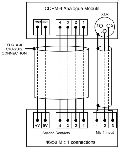
In this use case, an installation of four zones is considered, where the CDPM-4 is to be used in conjunction with a 46/50 mixer-amplifier. There is a requirement for a single paging point, so no further microphones will be required.
The 46/50 only supports paging microphone connection via a set of analogue access contacts, so the CDPM-4 will require the analogue interface module. Section 7.10 is used to determine which jumpers will need changing to configure the Mic 1 input on the 46/50 for use as a paging microphone input, since this input is a dual purpose input. Since there is only a single microphone, this unit can be powered from the mixer connections, a CDPM-PSU will not be required.
Since the installation is small, there is no requirement for the group buttons to be set so the microphone jumpers can simply be set for operation without initialising any groups. J9 is set to ON to prevent any groups being set and J10 is set to ON in order to clear a zone selection once the call has been made. All the other jumpers inside the unit can be left at the factory default settings.
Connections between the two units are shown on the diagram below.
Figure 9.1.1: Connections between a single CDPM-4 and a 46/50
PWR GND +V 0V 4 3 2 1 1 2 3 CDPM-4 Analogue Module 46/50 Mic 1 connections 1 2 3 4
Access Contacts Mic 1 input
TO GLAND CHASSIS CONNECTION 1 2 3 XLR 11 V1 210605
CLOUD ELECTRONICS LIMITED
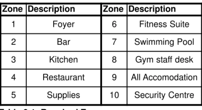
Let us consider an installation where a hotel is divided into 10 separate zones as tabulated below:
Table 9.1: Required Zones
Paging microphones are required in 4 locations : Reception (Zone 1: Foyer), Kitchen (Zone 3), Gym (Zone 8:Staff desk) and Security Centre (Zone 10). Both the Reception and Security Centre microphones need to access all areas, while the kitchen and gym microphones are only used on their domains. Further to this, both the security and paging microphone need to be prioritised so that their announcements will override announcements from the kitchen and gym. The mapping between access and microphone points is shown below:
Table 9.2: Paging point access and priorities
The Gym facilities (zones 6-8) require a separate set of audio sources to the rest of the hotel, so a Z4II four zone mixer is allocated for the Gym facilities. The remaining 7 zones are to be
distributed through a Z8IIeight zone mixer. The mixers can be used to power one microphone
each, so in this case, the Z8IIis used to power one of the CDPM-4 microphones and the Z4IIis
used to power the other CDPM-4. Both the CDPM-12 microphones will need to use separate CDPM-PSUs.
Paging Point Description Required zones Microphone type Priority
PP1 Reception 1-10 CDPM-12 High
PP2 Security 1-10 CDPM-12 High
PP3 Gym Desk 6-8 CDPM-4 Normal
PP4 Kitchen 2-5 CDPM-4 Normal
Zone Description Zone Description
1 Foyer 6 Fitness Suite
2 Bar 7 Swimming Pool
3 Kitchen 8 Gym staff desk
4 Restaurant 9 All Accomodation
5 Supplies 10 Security Centre
12 V1 210605 *RECEPTION* *SECURITY* GYM KITCHEN LEGEND TERMINAL CONNECTION RJ45 CONNECTION FROM OUT TO IN POWERED CONNECTION CDPM-PSU CDPM-PSU CDPM-12 CDPM-12 CDPM-4 CDPM-4 GYM Mixer Z4II
All Other Zones
CLOUD ELECTRONICS LIMITED
The first rack of equipment is to be located close to the kitchen, since this area is a service area and not in the public view. The second rack is placed in a storage area of the gym. To simplify the cabling between the different areas, it is determined that both the gym and kitchen CDPM-4s will have an analogue interface module installed. This allows each of these to be powered from a mixer, and means that there is no need for an analogue set of cables to run between the kitchen and the gym.
One of the installation requirements, is that certain groupings are set and recognised, but cannot be reconfigured by the end users of the microphones. As such the groups will be set on initialisation for the CDPM-12 microphones, and all microphones will operate with the group lock on to prevent users tampering with the group settings.
To initialise the microphones, the CDPM-PSU can be used to connect power to each of the units. To initialise a unit it will need to power up with the NVM reset jumper ‘ON’ (J7). Once the unit has powered up the zones that are not being used should be disabled. This is done by holding down the ‘CLEAR’ button and then selecting those zones which are to be disabled. Once the required zones have been selected, the ‘CLEAR’ button on the microphone can be released. For the CDPM-12 microphones, buttons 11 and 12 are to be disabled; for the Gym microphone, button 4 is to be disabled.
In this same initialisation stage, the CDPM-12 groups can be set. These are set by selecting the required zones on the display and then holding the appropriate group button until the selection begins to flash. The groups are to be set as follows:
Group A - Zones 1, 2 and 4 Group B - Zones 6 - 8 Group C - Zones 3 and 5 Group D - Not set
The security microphone is to use chime 1 from the available selection and the security microphone is to use chime 4. The other two paging points are not to use any chime.
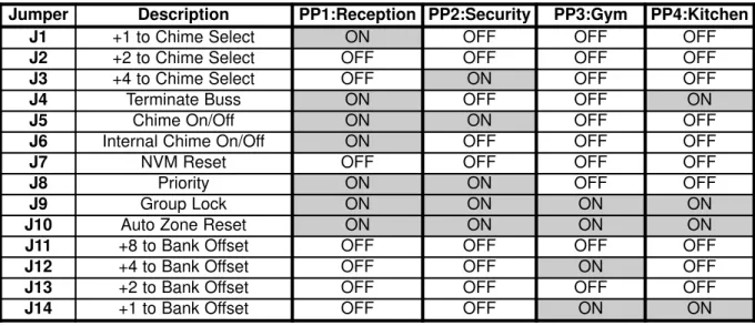
Once the initialisation of each of the microphones is complete, the power is disconnected and the units are configured for operation before they are installed. The operating jumper configuration for each microphone is shown in table 9.3 below:
Table 9.3: Operating jumper configurations for Paging Points
Once this configuration has taken place, the chime level on the Reception and Security microphones will need to be adjusted to an appropriate level using preset PR1 inside these microphones.
Jumper Description PP1:Reception PP2:Security PP3:Gym PP4:Kitchen
J1 +1 to Chime Select ON OFF OFF OFF
J2 +2 to Chime Select OFF OFF OFF OFF
J3 +4 to Chime Select OFF ON OFF OFF
J4 Terminate Buss ON OFF OFF ON
J5 Chime On/Off ON ON OFF OFF
J6 Internal Chime On/Off ON OFF OFF OFF
J7 NVM Reset OFF OFF OFF OFF
J8 Priority ON ON OFF OFF
J9 Group Lock ON ON ON ON
J10 Auto Zone Reset ON ON ON ON
J11 +8 to Bank Offset OFF OFF OFF OFF
J12 +4 to Bank Offset OFF OFF ON OFF
J13 +2 to Bank Offset OFF OFF OFF OFF
J14 +1 to Bank Offset OFF OFF ON ON
CLOUD ELECTRONICS LIMITED
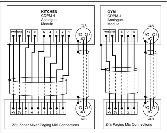
All connections to the mixers are done through the Gym (PP3) and Kitchen (PP4) microphones. As such these two microphones will require the additional analogue interface in order to connect to the mixers. Connections between these microphones and the mixers are shown in Figure 9.2 overleaf.
All that now remains is for the microphones to be physically installed and connected as required.
Fig 9.2.1: Access Contact Connections between PP3, PP4 and mixers
CLOUD ELECTRONICS LTD, 140 STANIFORTH ROAD, SHEFFIELD, S9 3HF ENGLAND. TEL: (+44) 114 244 7051 FAX: (+44) 114 242 5462
email: [email protected] homepage: www.cloud.co.uk +V PWRGND PWRGND 7 6 5 4 3 2 1 +V 0V 3 2 1 KITCHEN CDPM-4 Analogue Module GYM CDPM-4 Analogue Module
Z8 Zoner Mixer Paging Mic ConnectionsII Z4 Paging Mic ConnectionsII 1 2 3 4 5 8 7 6 9 10 0V 1 1 1 1 2 2 2 2 3 3 3 3 XLR XLR XLR XLR 14 V1 210605