Gravity-fed schemes
Introduction
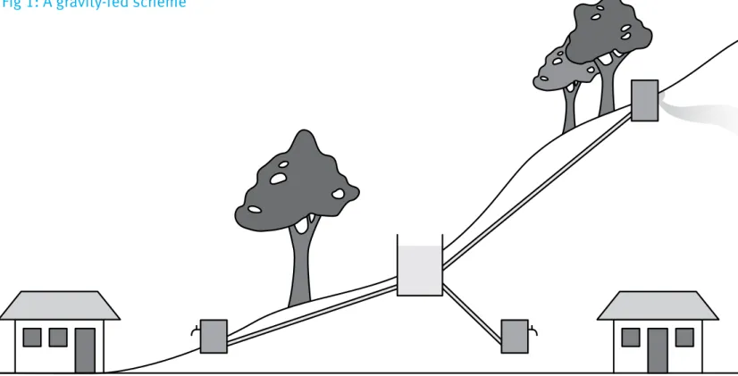
A gravity-fed supply from a small upland river, stream or spring, impounded within a protected catchment, is an example of a sustainable water supply technology requiring no treatment. An additional benefit is that, using the force of gravity, water can be transported by pipework to tapstands placed near to homes, reducing the work involved in carrying water.
The capital costs of gravity-fed schemes are, on average, higher than the costs of schemes that obtain water from underground sources. This is due mainly to the cost of long pipelines from the upland sources down to the villages and partly to the cost of providing storage tanks. However, running costs are usually low; maintenance includes simple tasks such as replacing tap washers and cleaning screens. Reliability is usually high and consequently the level of service is good. The usual components of a gravity-fed scheme are the source (stream, spring, catchment, dam or intake), main pipeline, storage and break-pressure tanks, distribution pipelines and tapstands.
Part of a series of WaterAid technology briefs. Available online at www.wateraid.org/ technologies January 2013
Feasibility of the scheme
The first phase in the creation of a gravity-fed scheme is a survey to determine the feasibility of the project. Influencing factors include village population, locally available materials, supply of skilled labour, and the quantity and quality of flow. The communities that benefit from the scheme usually commit large amounts of time and effort to the construction work.
Source
Springs and small streams are the most common sources for these
schemes. Whenever possible, a spring should be considered first as they are generally of better water quality and easier to protect against further contamination.
If a spring or stream is to be the source, it must be one that flows throughout the year, and the flow must be measured in the dry season in order to know the yield that can safely be relied upon. The maximum flow should also be determined by questioning the villagers for anecdotal evidence. While the safe/minimum yield is important for pipeline and reservoir design, the maximum flow is also necessary for estimating structural protection for the intake
Advantages of gravity-fed schemes
✓ Use of gravity negates the need for expensive pumps ✓ Low maintenance and running costs
✓ Consistent level of service due to low maintenance needs
✓ Tap stands within reasonable distance (250 metres) of all households
Disadvantages of gravity-fed schemes
✗ More expensive construction costs than underground sources ✗ Difficult terrain can restrict pipe-laying
✗ Yield can diminish or dry up during extreme drought periods ✗ Furring of pipes in hard water areas
and overflow requirements. When a spring is used, the spring head must be protected. The water must be piped directly from the eye of the spring to prevent pollution of the supply.
Catchment
The catchment area of a spring or stream must be free of animals and cultivation to prevent contamination of the source from chemical or biological matter. If only a small area is involved, it may be fenced off completely. Communities often enforce bylaws to exclude people and animals from the area.
Source development
When investigating a possible source, the surveyor must develop ideas about how the intake work will be built, for example, how to protect the structure against erosion, floods or contamination by surface water run-off. What amount of excavation will be called for and will a dam or drainage channel be required?
Dams in streams are generally small; their purpose is to provide a small pond so that a controllable draw-off pipe can be built into the wall of the dam at a level higher than the bed of the stream. Unlike larger dams, which impound water to provide storage
over a dry season, these small dams overflow for most of the time. The crest of the dam acts as an overflow weir, except at the sides where it is raised to prevent scouring of the banks.
A dam is usually constructed out of concrete, blockwork or masonry, preferably founded on solid rock. Rock, or some other impermeable material, should also form the basin of the impoundment. Twin intake pipes (one in use, one in reserve) are built into the wall of the dam; on the upstream side of the dam they have strainers or screens, on the downstream side they are fitted with control valves. A scour pipe is also built into the dam, at a low level, with a stop valve on the downstream side, and is used periodically to drain the pond and to clear accumulated silt.
Design
If the project is considered feasible, the surveyor must then conduct a topographical survey. The route of the pipeline from the intake to the storage tank must be surveyed and a drawing made of the optimum hydraulic gradient line, in order to determine the pipe size needed to deliver the design flow.
Main pipeline
In rocky areas, the main pipeline will probably be laid above ground and will be made of galvanised mild steel tubing, anchored on saddles. Elsewhere, the pipeline will be laid in trenches, to protect it from damage, and will usually be plastic pipe (MDPE – medium density polyethylene).
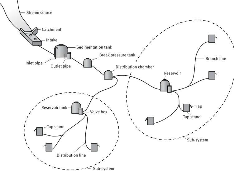
Fig 2: Components of a typical gravity-fed system
Stream source
Catchment Intake
Sedimentation tank
Break pressure tank
Distribution chamber Inlet pipe Outlet pipe Branch line Tap Tap stand Reservoir Distribution line Valve box Reservoir tank Tap stand Sub-system Sub-system
Break-pressure tanks
To reduce operating pressures it is sometimes necessary to introduce break-pressure tanks, which are usually made of concrete or ferrocement. If break-pressure tanks are used, the hydraulic gradient starts again at the tank water level. If suitably sized, these tanks can be used within the system as storage tanks to meet peak demand.
Reservoir storage tanks
Although a village’s water needs are based upon a minimum requirement (eg 25 litres per person per 24 hours), in reality, nearly all of this water will be required during the day. Reservoir storage tanks serve to store water provided by the source during low demand periods (overnight) for use during high demand periods (early morning). They are usually constructed within the system to provide a total volume of storage equivalent to one day’s consumption. If there are no break-pressure tanks, they may also be sited so as either to limit the maximum pressure in distribution pipelines or to sustain a pressure of at least three metres head at each tapstand, while meeting the peak demand in the morning and evening.
Capacities of tanks range from 10 to 100 cubic metres, depending upon the size of the population to be served. Various materials have been used to construct them: masonry, reinforced concrete, concrete
blockwork, ferrocement, galvanised mild steel, and fibreglass panels. In flat areas, tanks may have to be elevated on blockwork support structures. Tanks are roofed and, typically, are provided with a float controlled inlet valve, twin outlet pipes with stop valves, a scour pipe at low level for emptying and cleaning out, and an overflow pipe led well
away from the tank. The roof of the tank should have a sealed access manhole and ventilators, covered in mesh fly screen, to allow air to be exhausted or admitted when raising or lowering the water level in the tank. When it comes to designing the reservoir tank, it is a common assumption to think the bigger the better. While this is desirable, there is little use in building any tanks so large that the source will never be able to fill it up during the overnight refilling period. The storage capacity of the reservoir is actually determined by the projected village water needs and the safe yield of the source. The actual dimensions of the tank are determined by its capacity, the conditions at the selected site, and the rules of economical design.
Distribution pipelines and tapstands • A distribution system of small
diameter MDPE pipes, laid in trenches, feeds tapstands around the village. Each tapstand should serve about 150 people and should be positioned so as to uniformly reduce the maximum distance people have to carry water.
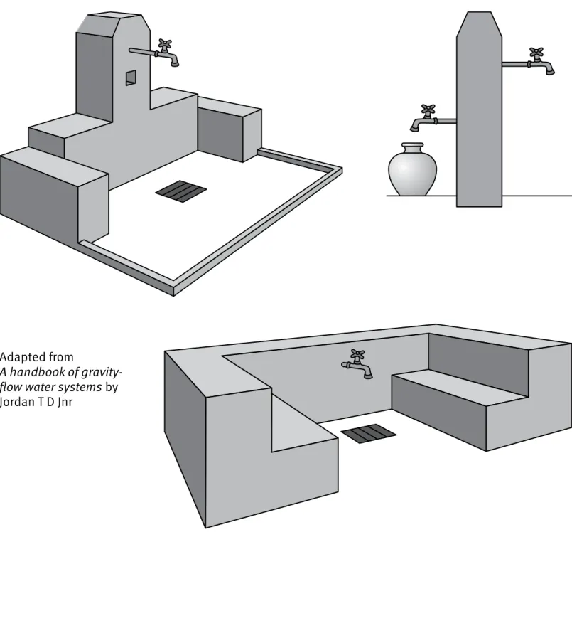
• Tapstands have several components: a concrete post supporting a 15 milimetre mild steel riser pipe from the pipeline up to a bibcock which should discharge at least 0.1 litres per second; a concrete stand on which to place a bucket; a concrete apron to collect spillage; and a gutter and drainage to a soakaway in order to prevent the breeding of mosquitoes and to keep the area clean.
• Tapstands should have a fence around them to keep animals away and each should have a nominated person, or caretaker, to keep the area clean and tidy.
Fig 3: Various designs of tapstands
Adapted from
A handbook of gravity-flow water systems by Jordan T D Jnr
References
Jordan T D Jnr (1984) A handbook of gravity-flow water systems. IT Publications
Case study
Construction of a gravity-fed scheme in Hitosa woreda
of central Ethiopia
Work underway on the gravity-fed scheme in Hitosa woreda, Ethiopia WaterAid/Caroline PennSince 1995, some 75,000 people in more than 40 communities in Hitosa woreda (district) in central Ethiopia have been provided with water through a spring-fed gravity water supply project that is one of the largest in the country.
The water for the main Hitosa scheme is sourced from two springs which are located at the head of a watercourse known as Burkitu, in the Hitosa woreda, some 164 kilometres south-east of Addis Ababa. The combined yield of the springs when surveyed in the 1990s was approximately 19.4 litres per second.
A retaining wall and collection chamber impound water from the main spring, prevent contamination and convey water into the reticulation (piped) system. The second spring, which is
much smaller, is impounded in a similar fashion and piped to the same chamber.
The main pipeline is 203 milimetre diameter ductile iron and 152 milimetre galvanised iron. Other sections are in PVC in diameters from 76-152 milimetres. The branch lines from the reservoirs are in MDPE with diameters from 25-63 milimetres. There is one break-pressure tank between the source and escarpment to the lowlands, where the villages supplied by this system lie.
Flow controls are installed on the reservoir inlets, ensuring a steady but even high pressure in the system and avoiding considerable maintenance.
Water source Capital cost Running cost Yield Bacteriological water quality
Situation in which technology is most applicable
Spring protection
Low or medium if piped to community
Low High Good if spring catchment is adequately protected
Reliable spring flow required throughout the year
Sand dams Low – local labour and materials used
Low Medium/high – depending on method used to abstract water. Water can be abstracted from the sand and gravel upstream of the sand dam via a well or tubewell
Good if area upstream of dam is protected
Can be constructed across seasonal river beds on impermeable bedrock
Sub surface dams
Low – local labour and materials used
Low Medium/high – depending on method used to abstract water. Water can be abstracted from the sand, gravel or soil upstream of the sub-surface dam via a well or tubewell
Good if area upstream of dam is protected
Can be constructed in sediments across seasonal river beds on impermeable bedrock Infiltration galleries Low – a basic infiltration gallery can be constructed using local labour and materials
Low Medium/high – depending on method used to abstract water
Good if filtration medium is well maintained
Should be constructed next to lake or river
Rainwater harvesting
Low – low cost materials can be used to build storage tanks and catchment surfaces
Low Medium – dependent on size of collection surface and frequency of rainfall
Good if collection surfaces are kept clean and storage containers are well maintained
In areas where there are one or two wet seasons per year
Hand-dug well capped with a rope pump
Low Medium – spare parts required for pump
Medium Good if rope and pump mechanisms are sealed and protected from dust. Area around well must be protected
Where the water table is not lower than six metres – although certain rope pumps can lift water from depths of up to 40 metres
Hand-dug well capped with a hand pump
Medium Medium – spare parts required for pump
Medium Good if area around well is protected
Where the water table is not lower than six metres
Tube well or borehole capped with a hand pump Medium – well drilling equipment needed. Borehole must be lined
Medium – hand pumps need spare parts
Medium Good if area around borehole/tubewell is protected
Where a deep aquifer must be accessed
Gravity supply High – pipelines and storage/flow balance tanks required
Low High Good if protected spring used as source
Stream or spring at higher elevation – communities served via tap stands close to the home Borehole
capped with electrical/ diesel/solar pump
High – pump and storage expensive
High – fuel or power required to run pump. Fragile solar cells need to be replaced if damaged
High Good if source is protected
In a small town with a large enough population to pay for running costs
Direct river/lake abstraction with treatment
High – intake must be designed and constructed
High – treatment and pumping often required. Power required for operation
High Good following treatment
Where large urban population must be served Reverse osmosis High – sophisticated plant and membranes required
High – power required for operation. Replacement membranes required
High Good Where large urban population must be served
Household filters
High – certain filters can be expensive to purchase/produce
Filters can be fragile. Replacement filters can be expensive or difficult to source
Low Good as long as regular maintainance is assured
In situations where inorganic contaminants are present in groundwater sources or protected sources are not available
SODIS (solar disinfection)
Low – although clear bottles can be difficult to source in remote areas
Low Low Good In areas where there is adequate sunlight – water needs to be filtered to remove particulate matter that may harbour pathogens before SODIS can be carried out effectively. SODIS is not appropriate for use with turbid water
WaterAid transforms lives by improving access to safe water, hygiene and sanitation in the world’s poorest communities. We work with partners and influence decision-makers to maximise our impact. Registered charity numbers:
Australia: ABN 99 700 687 141
Sweden: Org.nr: 802426-1268, PG: 90 01 62-9, BG: 900-1629
UK: Registered charity numbers 288701 (England and Wales) and SC039479 (Scotland)