BASED ON A DESIGN PHILOSOPHY FOR THE NEXT GENERATION
OF GRAPHICS PACKAGES
By
HELEN JEAN VRENJAK, B.Sc.
A Project
Submitted to the School of Graduate Studies in Partial Fulfilment of the Requirements
for the Degree Master of Science
McMaster University October 1984
MASTER OF SCIENCE (1984) (Computation)
mcmaster university
Hamilton, Ontario
TITLE: The Design of MacPac - A Graphics Subroutine Library Based on a Design Philosophy for the Next Generation of Graphics Packages
AUTHOR: Helen Jean Vrenjak, B.Sc. (McMaster University)
SUPERVISOR: Dr. P.J. Ryan
NUMBER OF PAGES: vii, 171
This paper presents the design of a graphics subroutine library, MacPac, as a contribution to the development of a standard for future graphics packages. The need for a new graphics standard, and hence the motivation for the development of MacPac, is illustrated through a de tailed discussion of existing graphics standards and systems. MacPac is based on a design philosophy developed by Mark Green for the next generation of graphics packages. It addresses the hardware and software ideas of the 80's, incorporating and building upon the valuable and te sted ideas of a number of existing graphics systems. The design languages used in the development of MacPac were created by Mark Green for the design of user interfaces. This work examines the effectiveness of these languages in the design of a graphics system.
ACKNOWLEDGEMENTS
I would like to express my gratitude to both Professor Mark Green and Dr. Pat Ryan. Professor Green provided the impetus behind this project, along with the design philosophy and design languages used in the development of MacPac. Dr. Ryan was instrumental in the completion of this work. I an very grateful for his patience and guidance throughout the past few months.
I would like to thank all those friends who supported, encouraged, and maintained me throughout this work. The fact that many of these people still speak to me is testimony to their monumental understan ding.
Finally, I would like to thank my family for their continuous sup port, encouragement, and faith in me. Special thanks go to my father for his patience, endurance, and (very importantly) skill in editing this paper. Last, but far from least, my husband, Milo. Thank you, Milo, for everything. I dedicate this work to these people.
Chapter 1 Introduction 1
Chapter 2 Graphics Packages Today 5
2.1 The Current Standards - GKS and Core 7
2.1.1 Methodology 7
2.1.2 GKS and Core - Description and Comparison 8
2.2 Mainstream Methodology Revisited 14
2.2.1 Portability and Device Independence 14
2.2.2 Separation of Input and Output 16
2.2.3 The Synthetic Camera Analogy 17
2.2.4 Resource Management 18
2.3 Resource Management Systems 19
2.3.1 Transformations 20
2.3.2 Segmentation 22
2.3.3 Attributes 23
2.3.4 Input 23
2.3.5 Object-Oriented Systems 24
Chapter 3 Introduction to MacPac 26
3.1 Motivation 26
3.2 Design Philosophy Behind MacPac 28
3.3 The Design Languages 32
3.3.1 The User Modeling Language - UML 34
3.3.2 The Specification Language - GUSL 35
3.3.3 The Base Language 38
Chapter 4 The User Model 41
4.1 Objects 41
4.2 Operators 49
Chapter 5 Display Considerations 60
5.1 Objects 61
5.2 Operators 67
Chapter 6 Specification of MacPac 90
6.1 MacPac Modules 91
6.2 Graphical Primitives 124
Chapter 7 Conclusions 137
Appendix A UML and GUSL 144
1 Language Structure - Constructs 144
1.1 UML Constructs 144
1.2 GUSL Constructs 145
1.3 The Base Language - Special Forms 148
2 Pre-defined Theory Operators 149
3 Grammars 150
3.1 Base Language Grammar 151
3.2 UML Grammar 152
3.3 GUSL Grammar 154
Appendix B Basic Graphical Entities 157
1 Raster_display Specification 157
2 Transform Specification 158
3 Colourjnap Specification 161
Appendix C Compendium of Operators 163
1 Display Manipulation Operators 163
2 Image Manipulation Operators 164
3 Figure_Transform Manipulation Operators 166 4 Input_Device Manipulation Operators 168
REFERENCES 169
Figure 2.1 Mainstream Transformations 9
Figure 2.2 Mainstream Input Classes 13
Figure 4.1 An Example of a MacPac Application 45
Figure 6.1 World Specification 96
Figure 6.2 Display Specification 102
Figure 6.3 Image Specification 115
Figure 6.4 Figure_transform Specification 120
Figure 6.5 Input_device Specification 123
Figure 6.6 Input_event Specification 124
Figure 6.7 Line Specification 127
Figure 6.8 Polyline Specification 128
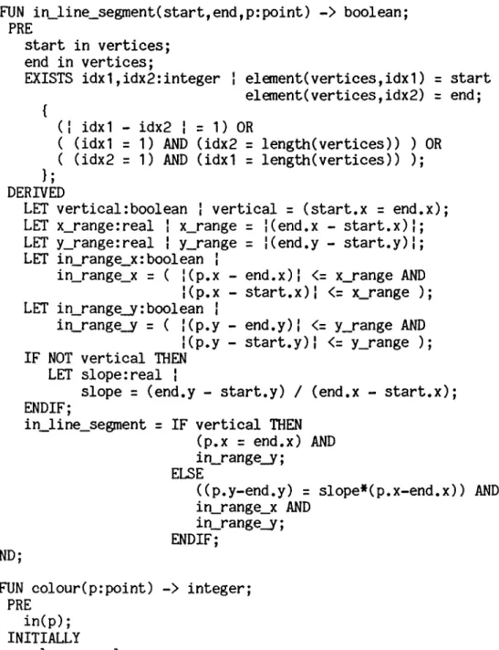
Figure 6.9 Character and Font Specifications 132
Figure 6.10 Text Specification 134
Chapter 1 Introduction
A salient feature of current computer use is the demand for in teractive graphic control. From home computers with their video displays to computer-assisted design and manufacturing facilities, the user expects to manipulate and modify images. He also supposes that this capability will be universal; viz, that what can be done in one environment on a particular system can be done anywhere. This creates a new set of problems for the developers of graphics software systems, and for the applications programmers who use these systems.
The design of graphics software systems, or graphics packages, is an important aspect of computer graphics. Without this software, the rate of production of graphics application programs would be very slow and only expert programmers would be competent to write them. It would be impossible to exploit the potential uses of computer graphics [Newman and Sproull 19791. However, the constant improvement of both input and output hardware creates an environment of exasperating fluidity for the designers of these interactive graphics packages.
In the early years of computer graphics, a display was typically driven by a device-dependent subroutine package provided by its manufacturer. As graphics terminals became more widely available,
device-independent packages capable of driving a wide variety of display devices came into general use. The main goal for device inde pendence was the promotion of program and programmer portability. Dif ficulties in transporting application programs between sites, and the necessity to retrain graphics programmers to understand the idiosyn- cracies of each new graphics installation encountered, were major de- terents to potential graphics users [Newman and Van Dam 1978]. A device-independent graphics package used in conjunction with a high level programming language had the potential to alleviate these por tability problems considerably. Unfortunately, because of the wide variety among these device-independent packages, portability was still limited to those sites having the particular graphics package used to develop the application.
By the early 1970*s, the need for standardized computer graphics practices was widely recognized. The prime advantage of graphics standards is improved program and programmer portability. With a standard, graphics software developers are assured that their applica tion programs will run on any computer or terminal, and graphics users are free to choose anong vendors for satisfaction of their software re quirements. For the graphics hardware manufacturer, a standard gives guidance for future directions in hardware development and increases the size of the market. It is easier to sell a new computer with its latest graphics hardware when it does not demolish the user's graphics software library. A standard may also solve the problem of picture por tability by graphics-containing database portability. When a picture
3
can be represented as database items, the appropriate representation and storage standards permit the picture to be displayed by different computers on different display devices and result in the same visual image [Hindin 1984].
What emerged were two major standards proposals, the Core system and the Graphical Kernel System (henceforward GKS), tailored to the needs of the vector display hardware of the *70’s. As these were being established, significant advances occurred in display device tech nology; e.g. the microprocessor-controlled raster display device. Our approach to software has also changed with the passage of time. This evolution of both hardware and software raises a question as to the suitability of our present graphics standards for current applications.
This work presents the design of a new graphics package as a step in the direction that software systems must take to best accom modate the hardware and software ideas of the *80’s. In this context we shall illustrate the influence of the new technology and the new software approach on the design of graphics standards.
Chapter 2 takes a closer look at what is available today in graphics software. Core and GKS, as the current standards, are ex amined in some detail. Their methodology is presented, followed by a description, and an examination of some methodological problems that emerged during their implementation and use.
A second stream of graphics packages is then described, these frequently being oriented to raster displays. A common feature of this second stream is that they attempt to control the allocation of available graphical resources. Two examples of these systems (CANVAS and GiGo) are presented. A brief description of object-oriented graphics systems is also provided, as these represent a new and dif ferent approach to the design of graphics software.
An introduction to our new graphics system, MacPac, is pre sented in Chapter 3» MacPac, acronym for McMaster Package, is a graphics subroutine library based on a design philosophy developed by Mark Green [Green 1982a], This philosophy, which addresses the next generation of graphics packages, combines and enhances ideas from the second stream of systems mentioned above. Chapter 3 examines the motiva tion for the development of MacPac and introduces the underlying design philosophy. A secondary purpose for this work is also introduced. Green [Green 1981] has developed a notation for the design of graphical user interfaces. It is used in the design of MacPac to determine whe ther its effectiveness extends to the design and specification of a graphics system.
Chapters 4,5, and 6 present the design of MacPac from an ini tial user’s view to a complete specification of the system.
Chapter 2
Graphics Packages Today
Among the first groups to concentrate on a standardized ap proach to computer graphics software were the ACM SIGGRAPH Graphics Standards Planning Committee (henceforward GSPC), formed in 1974, and the Graphics Subcommittee of IFIP Working Group 5.2 (henceforward WG5.2), formed in 1975. The early efforts of GSPC produced few tangible results and progress was slow. Although possessing a large body of knowledge on which to base the design of a software standard, the GSPC lacked a corresponding methodology. The IFIP WG5.2 Graphics Subcommittee focused attention on this requirement. In 1976 it spon sored the successful Workshop on Graphics Methodology at Seillac, France.
This workshop, by directing attention to several issues in graphics system design, had a profound effect on the later work of the GSPC [Newman and Van Dam 1978], The result is the widely known specification for a core graphics system called Core, published in 1977 and revised in 1979. Another group stimulated by the "spirit of Seil- lac" was the German National Standards body, Deutsche Institut fur Nor mung (DIN). This Group developed several early versions of the Graphical Kernel System (GKS). The International Standards Organiza
tion (ISO) Working Group on Computer Graphics, containing representa tives from the American National Standards Institute (ANSI), DIN, and other national standards bodies, has since modified GKS to its present version and made it a Draft International Standard [Simons 19831.
The development of graphics software can be separated into two major streams [Rosenthal 19831. The mainstream, exemplified by GKS and Core, concentrates on viewing, segments, output primitives, and virtual input devices. The second stream, called the RasterOp stream by Rosen thal, attempts to provide facilities whereby graphical resources can be managed. The important concepts here are windows, the refresh hierar chy, and pointing for input. Differences in the two streams may at first appear to reflect the hardware addressed, but the window manager graphics system GiGo (Graphics in/Graphics out), driving storage tube terminals, refutes this [Rosenthal 19831. ’’Resource management stream” is perhaps a more comprehensive name for this second stream of software development.
This chapter examines the two streams in more detail. Charac teristics of mainstream systems are followed by a discussion of problems encountered in mainstream methodology. Finally, resource management stream systems are considered.
7
¿J__ The Current Standards.- GKS and Core
A major force in the development of GKS and the Core System was the 1976 IFIP WG5.2 Workshop held at Seillac. This workshop produced a design methodology that underlies both systems. We discuss this aspect before providing details of the systems.
¿U__ Methodology
The methodology, set out in SIGGRAPH’s 1979 specification for the Core System [GSPC 19793, may be summarized as follows [Rosenthal 1981]:
- The primary objective of a standard is program and programmer portability. It should be possible to move a program from one environment to another without requiring structural changes. Portability also encompasses the concept of device independence, whereby application programmers are insulated from the
peculiarities of particular devices.
- Input and output functions should be separated. Input device ac cess should be in terms of the type of value the device returns; this is the concept of virtual input devices [Wallace 1976].
- Two coordinate systems should be supported, the world coordinate system in which the picture for display is constructed, and the device coordinate system in which the data to be displayed are represented. Data in world coordinates are converted to device coordinates by invoking a viewing operation.
- A display file, containing a description of the picture in device coordinates, should be used. Individually modifiable display file segments, each independent of the other, permit manipulation of the picture.
- There should be a distinction between functions involved in main taining the description of a picture, modelling functions, and those supporting generation of a picture, viewing functions.
2.1.2, GKS..and-CfiTA r Description .an.d...£Qfflparlaon
The description of GKS and the Core System that follows provides an overview of these systems with respect to some important concepts in graphics software. More detailed information on the Core and GKS may be found in the Status Report of The Graphics Standards Planning Conmittee [GSPC 19791 and the Computer Graphics Special GKS Issue [X3H3 1984].
2J..2a Transformations
Viewing, as introduced at the Seillac workshop, is based on the synthetic camera analogy. In this analogy, a scene in world coordinate space is viewed on a display screen as if by a camera located at a single point in that space (Figure 2.1a). The camera handles the trans formation of the scene from world coordinates to the coordinates of the display medium.
9
World Coordinates
i i i i
! View Transform i
Device Coordinates
Figure 2.1a - Synthetic Camera Analogy
World Coordinates I I I I ' View Transform i i i i i
Normalized Device Coordinates
Figure 2.1c - GKS Transformations i Device Transform 1 1 ! ! Device Transform | i i i i i i
! Device Coordinates ! ! Device Coordinates !
Figure 2.1b - Core System Transformations
i World 1 Coordinates 1 1 World 2 Coordinates | 1 1 1 View Transform 1 1 1 1 1 1 1 1 ! ' View Transform I 1 1 1 1 1 1
! Normalized Device Coordinates 1
1 Ì Device Transform 1 1 1 1 1 1 1 1 i ! Device Transform J 1 1 1 1 1 1
! Device Coordinates 1 I Device Coordinates i
In practice, however, this simple analogy cannot accommodate the requirements of either Core or GKS. The stated objective of device independence is extended by both groups to include the ability for the same program to drive different devices simultaneously. To accommodate this, the single transformation from world coordinates to device coordinates required by the synthetic camera analogy is split into a two-stage process. First, world coordinates are transformed to nor malized device coordinates. From there a device-specific transforma tion is used to transform the scene to the coordinates of the chosen device. The Core System supports a single global transformation from world to normalized device coordinates (Figure 2.1b).
In the vast majority of applications, however, several world coordinate systems and/or several different views are required in the generation of a picture. When only a single viewing transformation is available, the application program must recreate the correct viewing transformation, both on output when modifying the display, and on input for the conversion of locator coordinates to the appropriate world coordinates. These considerations led GKS to support multiple normaliza tion transformations (Figure 2.1c). [Rosenthal 1983).
2.1.2b Segmentation
The concept of segmentation handles the problem of selective modification. After a picture of an object has been created, the user may decide to change one area of the object. When the application
11
makes the desired change to the underlying data structure, an updated picture must be generated. A brute force approach recreates the entire picture, but both Core and GKS avoid this inelegant solution by the use of segments.
The description of an object is partitioned into segments that are individually displayed, and therefore individually modifiable. Each output segment contains a collection of logically related (as deter mined by the application programmer) output primitives that are to be manipulated as a whole. The application programmer may create segments at will. Initially the segment is in an open state and any primitives output while it remains open become part of the segment. Thereafter, the output primitives contained in a segment are subject only to changes to the segment attributes. In both GKS and Core only one seg ment may be open at a time. It is worthwhile to note that for these mainstream systems ’’[segmentation] also addressed the problem of refre
shing the picture after changes, storing a description of the picture as output primitives in a segmented display file. The range of per mitted [segment] manipulations was modelled on the capabilities of a
typical refresh vector display, highlighting, visibility and detec tability changes, and segment transformations” [Rosenthal 1983].
2 J..2.Q . Attributes
There are several types of attribute supported by mainstream systems. Global, or output primitive, attributes apply to primitives as they are generated and are not subject to retroactive modification. At tributes of this type may control the geometric aspects of a primitive, such as the height, width, and style of a character, or may simply de termine the appearance of a primitive, such as the style (dashed, dot ted, solid, etc.) of a line. Segment attributes are assigned to seg ment by name and may be altered at any time. These attributes, which affect all primitives contained in a segment, control features such as the visibility and highlighting of the segment. [X3H3 1984] [GSPC 19791.
Additionally, GKS supports workstation attributes. An example of this is "SET COLOUR REPRESENTATION", whereby the colour to be as sociated with a particular colour index on a particular workstation is specified [X3H3 1984]. GKS offers another feature, the bundling of at tributes, which is not supported by the Core System. Several non geometric attributes may be grouped under a single identifier that is an index into a bundle table. The index becomes the single attribute of the primitive under consideration and, as each workstation has its own bundle table, the appearance of this primitive may be different on different workstations [X3H3 1984].
13
2 J , 2d. Virtual Input Devices
The input facilities of these mainstream packages are built upon an extended concept of virtual input device. The pure virtual device concept specifies that the only visible aspect of a device is the type of value it returns. In practice it is obvious that virtual devices require other visible aspects to enable control of the operator interface. For example, the ability to control the prompt, echo, and initial value of an input device is required. This extended concept is known as the logical input device concept [Rosenthal 1982],
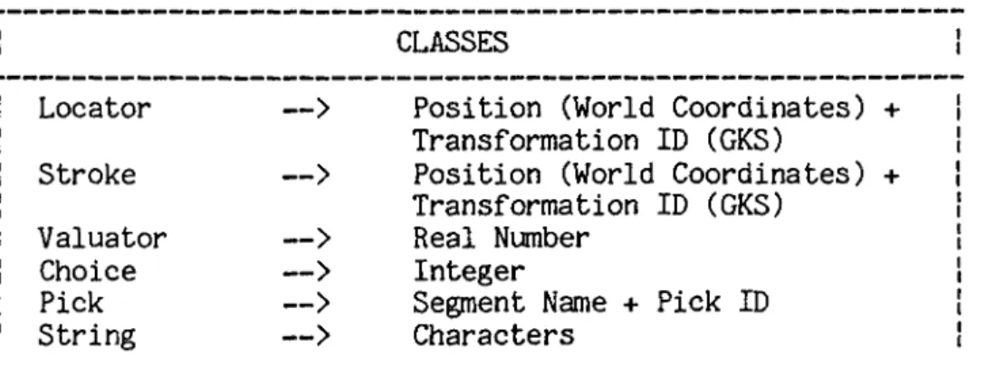
In the mainstream, each input device is assigned to a class de pendent on the type of value the device returns, and is accessed in terms of this class. The six possible classes are listed in Figure 2.2. Additionally, information can be obtained from each device in dif ferent modes. The three modes used by Core and GKS are EVENT, SAMPLE, and REQUEST. In EVENT mode the input device creates event records and
CLASSES
Locator
—>
Position (World Coordinates) Transformation ID (GKS)Stroke
—>
Position (World Coordinates) Transformation ID (GKS) Valuator—>
Real NumberChoice
—>
IntegerPick
—>
Segment Name + Pick IDString
—>
Charactersadds them to an input queue. When the application requests input from a device in this mode the first record in the queue is returned to the program. In SAMPLE mode the device is simply polled for its current value when information is desired. If an application requires informa tion from a device in REQUEST mode, it is suspended until this input becomes available. Each device has attributes which specify initial values, restrictions on values returned, and parameters for echo im plementation. [Rosenthal 19831.
Throughout their development, the proposals for GKS and the Core System were subjected to intense international review. This review identified certain problems inherent in the methodology. In some areas solutions were found which appear to be in conflict with the methodology, while in others the solutions appear unsatisfactory and remain controversial [Rosenthal 19811.
2.2.1__
Portability and Device IndependenceEarly in the development of these standards proposals, it was recognized that the objective of portability is in conflict with the requirement for high-quality user interfaces. In conjunction with the extended definition of device independence, portability requires that the graphics package be sufficiently general to drive any device. However, to provide for high-quality interaction the application must be tailored, or be able to tailor itself, to the particular hardware
15
involved. To establish a standard which impedes the construction of high quality user interfaces will tend to reduce the overall quality of applications. Both Core and GKS therefore sacrificed rigid adherence to the methodology to provide mechanisms that allow the application programmer to take advantage of the available hardware in the creation of a user interface.
One partial solution to the problem, adopted by GKS, is to let the application program inquire as to the capabilities of the device it is driving [Encarnacao 1980]. Unfortunately, the application programmer must then anticipate the peculiarities of the all devices to be driven in the future. This involves a large amount of extra code and, because the required path through the code is chosen at run-time, this overhead must be carried whether needed or not [Rosenthal 1981].
Additionally, both Core and GKS provide functions that allow the application programmer access to the non-standard capabilities of intelligent terminals. In the Core System, the ESCAPE function allows the programmer to invoke non-standard function names. In GKS this facility is provided by DRAW, a generalized output function which enables the user to specify higher level graphics primitives. [Arnold 1980].
2.2*2,.. Separation of. Input, ana Output
Additional methodological problems involve the separation of input and output functions and the concept of virtual input devices. Experience shows that adherence to these concepts impedes the produc tion of high-quality user interfaces. Two important factors in the quality of the human interface are the actions required by the user to create input and the visual feedback received in response to this in put. When constructing an application using virtual input devices, however, the programmer simply selects the virtual device corresponding to the type of value desired. Also, when the functions of input and output are clearly separated, the programmer is not provided with the facility to specify what the echo for this input should look like. This places the responsibility for the design of user interfaces on the graphics system implementer, who may not know the application specific meaning of the input required. Another problem is that the application programmer has no idea what the user interface will look like if his program is run at another site, even though the hardware may be iden tical. [Rosenthal 1981].
The idea of virtual input device has created controversy in yet another area. As Rosenthal points out :
"The concept of virtual input device tends to segregate input devices into a number of different classes. This is in conflict with accepted wisdom in operating system design, where the objective is generally to unify the various sources of input into a single concept, such as the ’file’. The di versity of virtual devices is particularly confusing because each can be emulated by combinations of the others; there is no real basis for distinguishing them." [Rosenthal 19813.
17
The seriousness of these problems with respect to user inter face quality has led GKS and Core to partially abandon the methodology in this area. Both systems provide facilities which allow the user to exert some control over echoing. Additionally, the Core system has func tions for associating input devices into groups and GKS allows for the emulation of one type of virtual input device by another [Rosenthal 1981].
2.2.3 Th? Synthetic Camera. Analogy
The synthetic camera approach to viewing, introduced in the original Seillac methodology, leads, to a graphics system that supports only a single transformation. This transformation may be changed during construction of a picture but only the most recent or current transform is known to the graphics system. Unfortunately, the realiza tion of this concept results in problems for both input and output func tions. On input, although the user may position a locator device any where on the screen, the system is able to transmit meaningful world coordinates only for positions within the last image created, i.e. the image for which the viewing transform is known. To create more than one view of a picture, the transform must be altered and the entire picture reprocessed for each view. As was illustrated in Section 2.1.2a, both Core and GKS encounter difficulties with this aspect of the me thodology. GKS partially resolves these problems by supporting multiple viewing transformations. Because only one transformation may be active at any given time, however, this output problem persists.
2.2.4 Resource Management
A major influence in the design of both GKS and the Core System was the idea that a distinction should be maintained between the func tions of modelling and viewing. According to the methodology, the graphics system handles viewing. All modelling functions must be han dled externally by the application program. Related to this forced ex clusion of modelling functions, however, is the mainstream’s lack of mechanisms to control the allocation of real graphical resources.
Awareness of the need for graphical resource management was stimulated by the second Seillac workshop in 1979 which stressed the importance of building interactive applications from existing com ponents. To do this successfully requires management of the available graphical resources. It is a way of ensuring that, once an existing component is invoked, it will access only the graphical resources it has been allocated.
Conventional programming languages support a modular program structure that is hierarchical in nature. Parent modules may invoke submodules that may in turn invoke other submodules. To control the management of graphical resources within this structure requires a mechanism whereby the available resources may be allocated in a hierar chical fashion. A graphics package must assign descriptors to all graphical resources. Each part of an application may then manipulate only those resources whose descriptors it has access to. A calling module may pass descriptors for all or part of its graphical resources
19
onto a submodule. This type of control ensures that no part of the ap plication will have access to the resources belonging to another part. Specifically, no called module will have access to any resources which are not within the control of the module initiating the call. [Rosen thal 19833.
Neither Core nor GKS provides such a mechanism. These systems allow all parts of an application access to the entire view surface. There is no supported hierarchy of pictures on the display and each module can manipulate every picture. Also, any part of the application may access any input device. When input is received, the application must decide to which of its parts that input relates, and handle it ac cordingly. [Rosenthal 19833.
2.3 Recourse ManagCTren.t Systems
We now turn to the resource management stream of graphics systems. Here a consensus of ideas and methodology like that established for mainstream systems does not exist. Many of the graphics systems in this stream were developed for specific purposes and/or in unconventional languages such as Smalltalk [Ingalls 1981], LISP [Sproull 19793, and EDL [Green and Philp 19823. The resultant variability in these systems makes it difficult to discuss resource management packages as a group. For illustrative purposes, however, two of these systems are presented here: the CANVAS package, developed at Carnegie-Mellon as part of the SPICE project [Ball 19833, and GiGo, an experimental package developed at Edinburgh University [Rosenthal
1981]. Although CANVAS, written in Pascal, was developed for use with raster displays and GiGo, written in C, is used to drive storage tube terminals, the structures of the two systems are remarkably similar. As an aid to comparison, these resource management systems are ex amined in the same format used to describe the mainstream systems in Section 2.1.2. A brief description of object oriented graphics systems, of which the Smalltalk and EDL graphics systems are representative exam ples, is included at the end of this section. These systems present an interesting new approach to graphics programming and resource management.
2.3.1 Transformations
There is a significant difference between the two streams in their way of transforming data for display. Mainstream packages use three coordinate systems: world coordinates, normalized device coordinates, and device coordinates. Both GiGo and CANVAS support only two coordinate systems. Pictures described in world coordinates are transformed directly into device coordinates for the desired display.
In GiGo, the Window structure handles this transformation. Specified within each Window structure are two rectangular areas, one in application coordinates and the other in device coordinates. These areas represent a mapping between the two coordinate systems. Each Window also contains information as to which screen the Window is cur rently active on. [Rosenthal 1983].
21
When using CANVAS, an application creates a picture by sending output primitives to one or more ’’canvases". There may be as many can vases as the application desires and each of these is always available for output, even if this output is not to be visible. For a canvas to become visible it must be mapped to a rectangular portion of the display surface called a viewport. This mapping converts canvas (world) coordinates directly to viewport (device) coordinates. A canvas may be mapped to several viewports, but each viewport may display only one canvas. [Ball 19833.
As several viewports may overlap, CANVAS organizes active view ports into a hierarchical refresh tree. At the root of this tree is a special viewport which controls access to the entire display surface. An active viewport may have several child viewports, each describing a patch of the display, but these children will have visible effect only within the portion of the view surface controlled by their parent. A precedence order is established among siblings to handle any conflicts which may arise due to overlap of viewports at the same level of the refresh tree. The only way a viewport may be added to this tree is through a parent. If a module has access to a viewport descriptor, that module may create child viewports within this viewport’s display space but may have no effect on any other part of the display. [Ball 19833.
2.3.2 Segmentation
For mainstream systems, segmentation provides both a means of naming groups of output primitives for manipulation and a vehicle for storing a picture description for use in future regenerations. Al though GiGo and CANVAS do not support a segment concept per se, they possess other facilities capable of playing the same role.
In the GiGo system, the concept of segment is embodied in the Window structure. Each GiGo Window stores either a list of all graphical primitives contained in the window or a pointer to a routine capable of recreating the picture in the window. In this way, the Window structure corresponds not only to a patch of view surface but to all the graphics in that patch. GiGo Windows can also play the role of segments as symbols. In this capacity the Window contains the graphical primitives of a picture component but is not active on any screen. Other Windows may then reference this Window to incorporate its picture component.
In the CANVAS system the combination of canvas and viewport provides many of the same functions as segments do in the mainstream. Viewports may be added to and removed from the refresh tree just as seg ments may be made visible and invisible. Raster operations may be per formed within a canvas just as segments may be highlighted. Both seg ments and canvases represent collections of output primitives. Unlike segments, however, canvases are always open. The only picture storage provided by CANVAS is the bitmap; a description of the picture as primi
23
tives is not supported. A viewport may store its own complete bitmap and/or the bitmaps of other viewports which it obscures. At higher levels a picture is defined procedurally. When regeneration is re quired the system arranges for appropriate application code to be in voked. [Rosenthal 19833.
2.3.3 Attributes
Both CANVAS and GiGo support only a single type of attribute. In GiGo, all attributes are Window attributes. They are stored in the Window structure and are applied to all primitives belonging to the Win dow. Similarly, CANVAS attributes are canvas specific and are applied to all primitives sent to the particular canvas. With this form of at tribute control, a caller can create an attribute context for a callee to operate in; i.e. the callee will only be able to affect the at tributes of the canvas (or window) whose descriptor was provided by the caller. [Rosenthal 19833.
2.3.4 Input
Neither of these resource management systems support the vir tual input device concept used by the mainstream. Instead, all physical devices are mapped into a single input class. For CANVAS this input class, called the Key Event, returns an integer command code, a character, and an integer coordinate pair. The single input class sup ported by GiGo returns a device coordinate position and an integer code.
The handling of input information is also very different be tween mainstream and resource management packages. In the mainstream, all parts of an application can access input information from all devices. In contrast, GiGo and CANVAS ensure that the user’s input in formation is accessible only to the routine associated with the window being pointed to. When input is received the GiGo system scans all win dows active on the view surface until it finds a window containing the input's device coordinate position. The input routine for this window is then invoked with the input information and the window descriptor as arguments. In the CANVAS system, each canvas has an input queue to which Key Events directed to that canvas are added. A canvas never
sees irrelevant inputs.
CANVAS provides a facility whereby events sent to a canvas may be passed up the refresh tree to its parent. This is useful when the application program decides that a certain input cannot be handled at the received level. It is possible to imitate this facility in GiGo simply by calling the parent's input routine directly from the input routine of the child Window. [Rosenthal 19831 [Ball 19831.
2.3.5 Object-Oriented Systems
We conclude our discussion of current graphics packages with a brief overview of object-oriented graphics systems. These systems, which we consider to be part of the resource management stream, repre
25
the differences from the systems we have examined so far are sufficient to preclude discussion of object-oriented systems in the format previously used.
The object is the underlying concept in an object-oriented system. It may be defined as "a package of information and a descrip tion of its manipulation" [Robson 1981]. In this way, an object repre sents both data and the computational processes which manipulate this data. The information in an object is altered by sending a message to that object. The content of the message determines which object proce sses are invoked and thus the information to be updated. In an object- oriented graphics system, objects are used to structure images on a display. Each object is responsible for a single image and is al located a portion of the display surface. The object may have an af fect on the display screen only within this allocated area. These object-oriented systems support a small number of graphical primitives that are used to directly alter a raster display. [Green 1982a].
This brief description of object-oriented graphics systems is sufficient for the purpose of this work. Although the new ideas seen in these systems must be considered in any future development, the systems themselves are very specialized and are therefore not especially relevant to the development of future standards. If de sired, further information may be found in the documentation for the graphics systems of specific object-oriented languages. Two representa tive examples are the graphics systems for the object-oriented languages Smalltalk [BYTE 1981] and EDL [Green and Philp 1982].
Having reviewed some representative examples of the graphics systems available today, we turn to the design of MacPac. The under lying purpose of MacPac is to exemplify an approach that takes advan tage of current ideas in hardware and software. From a number of such developments the shape of a new standard graphics package might be ex pected to emerge.
3.1 Motivation
The progress of technology inevitably requires a corresponding evolution of the control software. Both Core and GKS were developed for the hardware of ten years ago. As an initial stage in the design of the Core system, GSPC surveyed the existing state-of-the-art software. Some prerequisites for inclusion in this survey were that a system be installed at several locations, have an established user base, and be oriented for use with a FORTRAN application program [GSPC 19773» Given the delay between the time a system is designed, developed, and acce pted for use by a number of groups, the systems used as models by GSPC were already years behind the frontier in terms of hardware tech
nology. The survey specifically excluded any system features which "de
27
pended extensively on unusual or uncommon hardware features. Thus matrix processors, raster display background/area commands and similar interesting features were excluded” [GSPC 19773.
Thus Core and GKS address the predominant display hardware of their time, the vector display. These devices, having few stand-alone capabilities, are controlled by the host computer and share its memory. In both systems they are driven by a display file. This model is not well suited to the microprocessor-controlled, raster-based displays that are predominant today. Additionally, the current stan dards do not provide facilities that allow the application programmer to take full advantage of the many capabilities of the modern intelli gent terminal.
Further, the approach to producing graphics applications software has changed since the establishment of the current standards. Initially a portable graphics standard was expected to reduce the cost of producing applications software, but this did not occur. In the development of a system the application programmer spends most time on the user interface and application data structures. Tools are becoming available to aid in these tasks; e.g. user interface management systems, graphical databases, special purpose modelling systems, etc. Ideally, any new standard should interface cleanly with these program development tools [Green 1982a],
The current awareness of a need for graphical resource manage ment is another area where our approach to graphics programming has changed. If the graphics package does not support resource management, the application program must assume this function.
Chapter 2 examined several resource managenent stream systems that address both current hardware and software ideas. In many cases the development of these systems responded to a need that could not be satisfied by the existing standards, or addressed methodological problems encountered in the mainstream. Most of these systems are oriented to very specific systems and/or applications. Many are written in uncommon languages that are not widely used or supported. We need a system capable of fulfilling the needs of a larger audience of graphics application programmers. It should incorporate the valuable features of, and exploit our experience with, existing systems.
^.2 Design Philosophy Behind MacPac
We present MacPac as a contribution to the development of a standard for future graphics packages. MacPac, acronym for McMaster Package, is a two-dimensional graphics subroutine library based on a design philosophy developed by Mark Green for the next generation of graphics packages [Green 1982a]. A summary of this philosophy is provided here.
29
Green chose the form of a subroutine library as the most viable structure for future graphics packages. This decision was prompted by the lack of success of alternatives such as special graphics languages and programming language extensions. Green also suggests limiting the system to two dimensions. As most applications do not require three dimensions, the inclusion of this capability in the graphics package becomes unnecessary overhead. An add-on subroutine library can usually fulfill the requirements of those applications that demand three- dimensional graphics [Green 1982a].
Two major concepts in Green's design philosophy are the figure and the image. The figure allows the programmer to divide a picture into logical entities that may be manipulated separately. In this sense, it plays the role of the segment in mainstream packages, and of the object, or process, in object-oriented graphics systems. In main stream systems, however, only one segment is available for output at a time, a segment may not be modified after creation, and segments may not refer to other segments. This makes the mainsteam segment a far more restrictive concept than is desirable. On the other hand, the use of a separate process for every picture segment is far more general than required by most applications. As an organizational entity, the figure falls somewhere between a segment and an object. [Green 1982a].
Each figure is composed of graphical primitives and/or calls to other figures. There is no limit on the number of figures in existence at a given time and no restriction on when a figure may be modified.
Figure modification is achieved either by changing one of its primi tives or changing some aspect of a called figure. The primitives of a called figure may be altered, or the transforms that position figures within their parent figure may be changed.
A figure becomes visible as a result of a two-stage process. First, the figure is associated with an image. An image specifies a list of figures and a coordinate space in which these figures may ap pear. The image is then associated with an area on one or more displays. Several images may appear on a single display. Overlap of images on a display is handled by a system of priority and overlap rules. Two coordinate systems are in use here. Images and figures are described in a user-defined coordinate system that may encompass any subset of the Cartesian plane. When an image is associated with a display in the second step of the display process, the contents of this image are mapped from user-defined coordinates into device coordinates.
In his design philosophy, Green supports the inclusion of three basic graphics primitives: text, line, and polyline. For the text primitive, a string of characters and a position indicating where this string is to be placed must be provided. Both end points of a line are required for the line primitive. Many graphics packages support the concept of a current position, thereby reducing the arguments required for specification of a graphical primitive. Unfortunately this concept becomes ambiguous when transformations are allowed in the application coordinate space. Also, most graphics displays use the idea of a cur
31
rent position, but this current position rarely coincides with that of the graphics package. Because of these problems, the notion of current position is not included in this design philosophy [Green 1982a],
Green also suggests the provision of a facility whereby the user may define his own graphical primitives. In a graphics ap plication, there are often graphical entities (shapes) that are used repeatedly throughout the program. A primitive definition facility enables the programmer to define these entities as graphical primitives. Thereafter, when an instance of one of these entities is required, it may be created through a simple declaration, just as line, text, and polyline instances are created.
Although Green’s design philosophy does not discuss input hand ling, it is such an important aspect of any graphics system that some mention of how MacPac deals with input is necessary. MacPac maps all physical input devices into a single class which returns a coordinate position, an integer code, and a character string. When input is received the image to which that input is directed is notified and provided with the returned information. The coordinate position received by an image is always specified in the user-defined coordinate system of that image. MacPac handles the conversion from device coordinates before transmitting the input information.
The design of MacPac follows the ideas expressed in this section. In the discussion of MacPac that ensues we turn first to a description of the user’s view (Chapter 4). This is elaborated by the inclusion of
display considerations (Chapter 5). A final specification of MacPac is then presented (Chapter 6). In both the description and specification of the system we make use of design languages developed by Mark Green. Before proceeding with our discussion of MacPac, an introduction to these languages and the manner in which they are used in this work is provided.
2L3_..The Design Languages
In his paper "A Specification Language and Design Notation for Graphical User Interfaces” [Green 1981], Mark Green presents a me thodology for the design of graphical user interfaces and a number of tools which support this methodology. The design methodology itself is in many ways user interface specific and is therefore of limited use to us in the development of MacPac. It is oriented towards the design of individual user interfaces whereas MacPac must support a wide variety of user applications and their interfaces. The tools introduced in this paper, however, provide a means of expressing design ideas that is not limited to the design of graphical user interfaces. As mentioned in Chapter 1, we will use these tools in the design of the MacPac system. In this way, we will examine their effectiveness in the design of a graphics system.
33
Major amongst these tools are a User Modeling Language (hen ceforward UML) and a Graphical User interface Specification Language
(henceforward GUSL). Both of these languages depend upon a base language in which all expressions and assertions are written. An over view of these languages is presented in this chapter. More information on the structure of the languages, including detailed grammars, may be found in Appendix A. (All information on these languages is taken from [Green 1981]).
Before going on to our discussion of these languages, however, a word on the tone in which they are used in this work is required. Throughout the development of the MacPac system, these languages were also experiencing developmental changes. The paper mentioned above ([Green 1981]) provides an introduction to the languages and a simple example but does not provide information sufficient for their use in an advanced application. Further information and examples may be found in some of Green’s later work (e.g. [Green 1982b]). Upon examination of these later examples, however, it becomes apparent that changes have been made to the languages since they were introduced in his 1981 paper. Unfortunately, these changes have not been published. As a re sult conflicting information on legal language constructs has been en countered on occasion. Because of these problems, we have used the languages as a descriptive tool in the design of MacPac. They should not be considered the basis from which a mathematical correctness analysis could be done. There are a number of loose constructs and these must be accepted as such. This does not invalidate their use in
the design of MacPac, however. The languages are useful in providing a clear and consistent design description.
3.3.J... Ihe User Modeling Language UML
The first step in the design of MacPac is a description of the user’s view of the system. In the case of MacPac, the user is the ap plication programmer. All objects which will be available to the user must be described. Operators must be provided to allow manipulation of these objects to suit the user’s requirements. Green refers to the model constructed to represent the user’s view of the system as the con trol model. The tool he provides to aid in creation of this model is UML.
The first major contruct in UML is the OBJECT construct. Ob ject definitions, which are similar to type definitions, are used to describe all objects in the user’s domain. There may be several in stances of a given object type. Each object is described by its at tributes. The type of an attribute may be either a base type (one defined in the base language), another object, or a defined theory. More information on theories will be provided later in this chapter.
The OPERATOR construct is used to describe how objects may be manipulated. An operator is defined by its pre and post conditions. The conditions themselves are assertions written in the base language. All assertions in the pre-condition part of an operator must be true for successful application of the operator. The assertions in the post
35
condition section determine the effect of the operator. The operator manipulates the neccessary objects to make all post assertions true. The specific entities to be manipulated may be indicated to an operator by way of input parameters. Also, an operator may return a value. The types of these input and output parameters must be specified in the operator definition. It should be noted that the only effect an operator has is that stated explicitly by its post conditions. The state of objects not explicitly manipulated does not change. For exam ple, if the purpose of an operator is to remove a given entity from a set, a post condition might be ’’NOT this_entity in set;”. This operator would remove only the specified entity from the set. All other en
tities in the set would remain unaffected.
The UML INVARIANT construct provides a means of describing aspects of the user’s view that are not readily expressed through the object and operator constructs. Each invariant is an assertion that must always be true. It is very useful in describing global charac teristics of the system and giving information on the relationships be tween objects.
3.3.2 The Specification Language - GUSL
Once the control model is created, it may be used as the star ting point for the specification of the system. The specification language developed by Mark Green, GUSL, is based on idea of state machines. Under this approach, a program is divided into a number of
state machines, each having a local state and functions capable of acce ssing and changing this state. Green likens a state machine to an ab stract data type. In GUSL, the MODULE construct is used to represent the state machines of a system. As for objects, there may be several instances of a single module.
There are four possible components in a GUSL module. The first two deal with declaration of the entities used and manipulated by the module. The PARAMETERS component specifies the parameters required to create a module instance. These may be used to give each module in stance the appropriate starting state. The DECLARATIONS component of the module may be used to declare variables for use within the module.
The third component is the DEFINITIONS component. GUSL allows the definition of syntax macros. Each macro consists of a type, the name of the macro, parameters input to the macro, and an expression that defines the macro. These macros, which are used to shorten the definitions of commonly used functions, make the contents of a module more readable.
The fourth module component is by far the largest. The FUNC TIONS component contains the function definitions of all module func tions that may be used to access and/or change a module's state. There are three types of GUSL functions: V functions (VFUN), 0 functions (OFUN), and OV functions (OVFUN).
37
The first type, V functions, are used to access and represent the state of a module. Each VFUN has three sections; a function header, pre-conditions, and a function body. The function header con tains the name of the function and declarations of all input parameters as well as the type of the value returned by the function. The pre conditions section contains those assertions that must be true before the function is invoked. The function body may be either a primitive or a derived function body. A primitive function body gives the initial value of the function. The value of a primitive VFUN may be hidden, in which case it may only be accessed from within the module. A derived VFUN may be used as an interface between the current module and other modules in the specification. A derived function body contains a number of assertions. These are similar to post-conditions in that the operation of the function serves to make these assertions true. One assertion must equate a value with the function name as the value to be returned from the function invocation.
0 functions are used to change the state of a module. The only way the value of a primitive VFUN may be changed is through an OFUN of the same module. No value is returned from an OFUN. Each OFUN con tains pre and post assertions. The pre assertions specify the condi tions under which the function may be invoked. When an OFUN is invoked, the post assertions are considered one at a time and in the order pre sented. The state of the module is modified for each assertion to make that assertion true. Note that, as a previous assertion may be af fected by one that follows, it is possible that not all post assertions will be true after an OFUN is invoked.
The structure of an OVFUN is similar to that of an OFUN. The only difference is that an OVFUN returns a value and so must therefore, at some point in the post-conditions, equate the function name with a value.
3.3.3
The major components of the base language are a set of theories and a number of special forms. Green defines a theory as a data type and the operations which may be performed on any entity of this type. There are a number of pre-defined theories in the base language; in teger, real, set, vector, enumeration, boolean, point, and extent. The operators of these pre-defined theories are presented in Appendix A. The base language also allows specifier-defined theories. A theory may be defined by use of a GUSL module. All operations which may be per formed on this new theory must be included as functions of the module. There are two ways of referencing a theory operator (GUSL function) :
1. module_name.function_name(function_parameters) 2. argument function_name module__name
The second form is only possible if the function has a single input parameter. The argument must be of the same type as this parameter. Every object in the UML and GUSL descriptions of the system must belong to one of the pre-defined or specifier-defined theories of the base language.
39
As mentioned earlier all expressions and assertions of UML and GUSL are written in the base language. An expression is made up of values, theory operators, and special forms. A value may be an object, variable, parameter, or literal. An assertion is simply an expression that has a true or false value. Both UML and GUSL deal with asser tions. In many cases two or more expressions are combined to create an assertion. The special forms of the base language are all assertions. There are a number of these special forms. The EXISTS and FORALL special forms provide a means of examining the objects of our system to see if at least one, respectively all, of these objects satisfies cer tain conditions. The LET special form allows for creation of a new en tity which meets specified requirements. The IF special form lets one choose the set of assertions to be satisfied based on the value of another assertion. More information on these special forms is provided in Appendix A.
Two special characters may also be found in base language expre ssions. The first is the single quote (’). This character is used in conjunction with an expression to indicate use of the old, or previous, value of the expression. For example, the expression :
a = *a + 1;
may be interpreted as ’’the current value of a is equal to the previous value of a plus one". The second special character is the question mark (?). This may be used in primitive VFUNs to indicate that the initial value of the VFUN is undefined. However, when a "?’’ is used, there must be an OFUN in the same module capable of modifying the value of that VFUN.
As we proceed with the design of MacPac, the structure and syntax of these design languages will become clearer. The constructs of UML and GUSL are fairly self-explanatory. This section has simply provided an overview of the notations we will be using in the design process.
Chapter 4 The User Model
The initial step in the design of MacPac is to describe the de sired external behavior of the system. As discussed in the next two subsections, this involves determining what basic entities a user will be dealing with when using MacPac and then describing the behavior of these entities.
U__Objects.
When using MacPac, the user is faced with a world containing a number of display devices. On each display may be seen one or more images, each of which is composed of one or more figures. As well as receiving this graphical information, the user is capable of entering information into the system via an input device. The UML OBJECTS created for these five basic entities (the world, display devices, images, figures, and input devices) are presented and discussed below.
From the user's point of view, the world may be described by the UML object :
OBJECT world;
ATTRIBUTE display_set : SET OF display; ATTRIBUTE image_set : SET OF image;
ATTRIBUTE figure_set : SET OF figure_transform; ATTRIBUTE primitive_set : SET OF primitive; END;
Every display, image, figure, and graphical primitive that exists in the user’s world, whether or not it can be seen or is being used at that particular point in time, is recorded in the appropriate attribute of the world object.
A display is formally described by the UML object :
OBJECT display;
ATTRIBUTE display_id : integer; ATTRIBUTE area : extent;
ATTRIBUTE contents : SET OF image;
ATTRIBUTE input_group : SET OF input_device; END;
The first attribute, "display_id", is an integer descriptor for the display. Each display in the user's world must have a unique ”display_id" between 1 and x, where x is the number of displays con tained in the "world.display_set". The next two attributes detail the size of the display ("area") and the set of images that it contains ("contents"). The "area" attribute of a display specifies the device coordinate system of that display. For an existing image to be seen on a display it must be added to the "contents" of the display. Also as sociated with each display is a set of input devices, "input group".
43
An image is defined by the object :
OBJECT image;
ATTRIBUTE contents : SET OF figure_transform; ATTRIBUTE positions : VECTOR OF extent;
ATTRIBUTE window : extent; ATTRIBUTE chosen : boolean;
ATTRIBUTE input_information : input_event; END;
Each image is made up of a number of figure_transforms. These figure_transforms are recorded in the "contents” attribute of the image and may or may not be seen when the image is added to a display depen ding on the attribute "window”. All figures are described in a user- defined coordinate system (UCS) which may encompass any subset of the cartesian plane. The "window" is also defined in the UCS and indicates what portion of the user’s "world" will be considered when that image is displayed. Thus an image can contain much more information than is displayed at any one time and selected portions can be brought to view by changing the "window" attribute of that image. When an image is added to the "contents" of a display, an area in the coordinates of that display must be specified. This area, or viewport, controls where on the display the image will be seen. The image attribute "positions" is used to record these viewports. The ith element of "positions" con tains the image's viewport on the ith display, i.e. the display whose "display_id" equals i. The value NULL is stored in the "positions" vector for all entries which correspond to displays on which the image does not appear. When an image is selected by the user, the attribute "image.chosen" becomes true and the information from the input device is stored in "input-information".
Figure_transforms are represented by the object :
OBJECT figure_transform;
ATTRIBUTE figure : element; ATTRIBUTE trans : transform; END;
where :
TYPE element = (primitive, SET OF figure_transform);
TYPE primitive = (line,text,polyline,user_defined_primitive);
Each figure_transform has two attributes, a ’’figure” and an associated transformation (’’trans”). The "figure” attribute may be either a graphical primitive, in which case the figure_.transform is referred to as elementary, or a collection of other figure_transforms, referred to as a composite figure_transform. Allowing one figure_transform to be defined in terms of others enables the user to define standard shapes and then use them in various figures. Although there are no formal re strictions, all the graphical information contained in a figure_trans- form should be logically related. The transformation associated with each figure positions that figure within a parent figure_transform or an image.
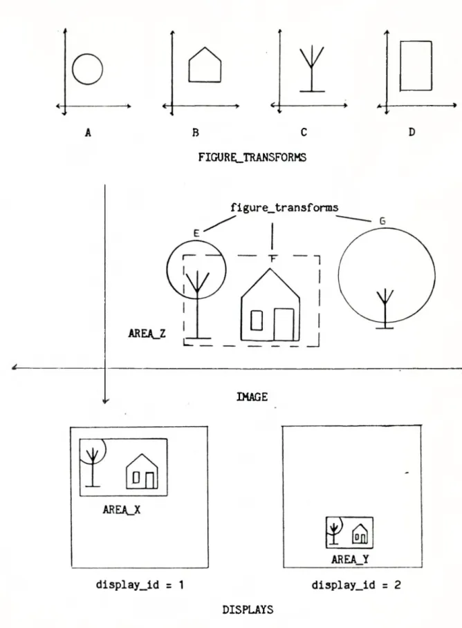
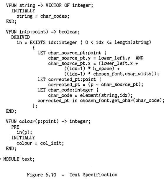
The relationship between figure_transforms, images, and displays is perhaps best illustrated by an example. Figure 4.1 pre sents a simple application of the MacPac system. The top of Figure 4.1 shows a number of figure_transforms which are independent of any image. Below this we see the coordinate space of an image. Three new figure_transforms have been created out of existing figure_transforms
B C FIGURELTRANSFORMS
figure_transforms
■>
IMAGE
Figure 4.1 - An Example of a MacPac Application DISPLAYS
and added to the ’’contents" of the image. We will examine figure_trans- form "E", which is meant to be a tree, in more detail. This figure_tran- sform is composed of two child figure_transforms. The "figure" at tributes of these children are figure_transforms "A" and "C". The "transform" attributes of the children position these figures together to create the tree. This tree is then positioned in the image by the "transform" of figure_.transform "E". The image’s "window" is denoted by the dashed rectangle, AREA_Z. The bottom of Figure 4.1 shows two displays which contain this image. The image is seen on each display in the viewport specified by the "positions" attribute of the image, i.e. the first element of "positions" would be AREA_X and the second element would be AREA_Y.
The last basic object a user encounters is the input device. For our input model all physical input devices are treated as a single object, defined by :
OBJECT input_device;
ATTRIBUTE where : point; ATTRIBUTE code : integer; ATTRIBUTE string : text; ATTRIBUTE enabled : boolean; ATTRIBUTE activated : boolean; END;
To be used for input an input_device must first be enabled, i.e. "enabled" must be true. While enabled, if the input_device is "ac tivated", by the user the incoming input information will be recorded in the attributes "where", "code", and "string". The user action
re-47
quired for activation may be a pushing a button, hitting the enter key, or one of many other input possibilities. Any activation of the in- put_device while it is not enabled is ignored. The attribute "where" specifies a point in device coordinates, "code" returns an integer code, and "string" contains a character string. If the particular device in use does not provide a point, an integer code, and/or a character string, the system will provide the missing information. This object is accompanied by the object input_event :
OBJECT input_event;
ATTRIBUTE where : point; ATTRIBUTE code : integer; ATTRIBUTE string : text;
ATTRIBUTE display_id : integer; END;
When an input_device is activated by the user, MacPac uses the at tribute "input_device.where" to determine which image the input informa tion should be sent to. The image selected is the image that appears on the display at this point. "Input_device.where" is then transformed into the UCS of the image and stored in "input_event.where". The in- put_device attributes "code" and "string" and the "display_id" of the display from which the input is received are also recorded in the in put-event. This object then becomes the "input-information" for the appropriate image.
Associated with these objects are a number of assertions which must always be true. The first of these invariants is :
INVARIANT
FORALL d:display ! d in world.display_set {
FORALL i:image ' i in d.contents {
EXISTS x:point ì x in elementii.positions,d.display_id) {
x in d.area; 1;
}; };
This specifies that each image contained in the "contents” of a display must be transformed into an area which falls at least partially within the "area" of the display. In other words, the viewport specified for an image when it is added to the "contents" of a display must overlap some portion of the "display.area". The second invariant states that the point associated with each "activated" input_device belonging to the "input_group" set of a display must fall within the "area" of the display :
INVARIANT
FORALL d:display i d in world.display_set {
FORALL id:input_device ' id in d.input_group AND id.activated {
id.where in d.area; 1;
};
The above assertions must be true for each display in the "world.display_set".
Each input_device may be associated with only one display. This may be stated formally as follows :
49
INVARIANT
FORALL d1,d2:display | d1 in world.display_set AND d2 in world.display_set AND d1 != d2
{
NOT EXISTS id:input_device ! id in d1.input group AND id in d2.input_£roup; };
The final invariant ensures that only one image may be chosen for input at any single point in time :
INVARIANT
FORALL i1,i2:image i i1 in world.image_set AND i2 in world.image_set AND i1 != i2
{
NOT (i1.chosen AND i2.chosen);
4.2 Operators
Having determined the basic objects a user will be dealing with when using MacPac, a description of the ways in which the user may manipulate these objects to meet his/her specific needs is required. The UML OPERATOR construct is used here to formally describe the behavior of our UML objects.
The first set of operators we will discuss are those which manipulate displays. Operators are required to control the visibility of an image as well as to change the placement of an image on a display screen. All these operators demand that the display to be manipulated be provided as an input parameter. In this way it is possible to en