EL5101, EL5101-0010
Incremental Encoder Interface
4.0
Version:
Table of contents
1 Overview Incremental Encoder Interface ... 5
2 Foreword ... 6
2.1 Notes on the documentation... 6
2.2 Safety instructions ... 7
2.3 Documentation issue status... 8
2.4 Version identification of EtherCAT devices... 8
3 Product overview... 13
3.1 Introduction ... 13
3.2 Technology ... 14
3.3 Technical data ... 17
3.4 Start ... 17
4 Basics communication ... 18
4.1 EtherCAT basics... 18
4.2 EtherCAT cabling – wire-bound... 18
4.3 General notes for setting the watchdog ... 19
4.4 EtherCAT State Machine ... 21
4.5 CoE Interface... 23
4.6 DC settings ... 27
5 Mounting and wiring ... 32
5.1 Installation on mounting rails ... 32
5.2 Installation instructions for enhanced mechanical load capacity ... 34
5.3 Connection system ... 35
5.4 Installation positions ... 38
5.5 Mounting of Passive Terminals... 39
5.6 ATEX - Special conditions ... 41
5.7 LEDs and connection... 43
6 Commissioning... 45
6.1 TwinCAT 2.1x ... 45
6.1.1 Installation of the TwinCAT real-time driver ... 45
6.1.2 Notes regarding ESI device description... 49
6.1.3 Offline configuration creation (master: TwinCAT 2.x) ... 53
6.1.4 Online configuration creation ‘scanning’ (master: TwinCAT 2.x) ... 59
6.1.5 EtherCAT slave process data settings... 68
6.1.6 Configuration by means of the TwinCAT System Manager ... 69
6.1.7 NC configuration ... 77
6.2 General Notes - EtherCAT Slave Application ... 80
6.3 Normal operation mode ... 89
6.3.1 Process data and modes - normal operation mode ... 89
6.3.2 Object description and parameterization - normal operation mode ... 93
6.3.3 Control and status byte ... 98
6.4 Enhanced operation mode... 99
6.4.1 Process data and modes - enhanced operation mode ... 99
6.4.2 Object description and parameterization - enhanced operation mode ... 106
7 Appendix ... 128
7.3 EtherCAT AL Status Codes ... 130
7.4 Firmware compatibility ... 130
7.5 Firmware Update EL/ES/EM/EPxxxx... 131
7.6 Restoring the delivery state ... 141
1
Overview Incremental Encoder Interface
EL5101-0000 [} 13] (Incremental Encoder Interface)
2
Foreword
2.1
Notes on the documentation
This description is only intended for the use of trained specialists in control and automation engineering who are familiar with the applicable national standards.
It is essential that the following notes and explanations are followed when installing and commissioning these components.
The responsible staff must ensure that the application or use of the products described satisfy all the requirements for safety, including all the relevant laws, regulations, guidelines and standards.
Disclaimer
The documentation has been prepared with care. The products described are, however, constantly under development. For that reason the documentation is not in every case checked for consistency with
performance data, standards or other characteristics. In the event that it contains technical or editorial errors, we retain the right to make alterations at any time and without warning. No claims for the modification of products that have already been supplied may be made on the basis of the data, diagrams and descriptions in this documentation.
Trademarks
Beckhoff®, TwinCAT®, EtherCAT®, Safety over EtherCAT®, TwinSAFE®, XFC®and XTS® are registered trademarks of and licensed by Beckhoff Automation GmbH.
Other designations used in this publication may be trademarks whose use by third parties for their own purposes could violate the rights of the owners.
Patent Pending
The EtherCAT Technology is covered, including but not limited to the following patent applications and patents: EP1590927, EP1789857, DE102004044764, DE102007017835 with corresponding applications or registrations in various other countries.
The TwinCAT Technology is covered, including but not limited to the following patent applications and patents: EP0851348, US6167425 with corresponding applications or registrations in various other countries.
EtherCAT® is registered trademark and patented technology, licensed by Beckhoff Automation GmbH, Germany
Copyright
© Beckhoff Automation GmbH & Co. KG, Germany.
The reproduction, distribution and utilization of this document as well as the communication of its contents to others without express authorization are prohibited.
Offenders will be held liable for the payment of damages. All rights reserved in the event of the grant of a patent, utility model or design.
2.2
Safety instructions
Safety regulations
Please note the following safety instructions and explanations!
Product-specific safety instructions can be found on following pages or in the areas mounting, wiring, commissioning etc.
Exclusion of liability
All the components are supplied in particular hardware and software configurations appropriate for the application. Modifications to hardware or software configurations other than those described in the documentation are not permitted, and nullify the liability of Beckhoff Automation GmbH & Co. KG.
Personnel qualification
This description is only intended for trained specialists in control, automation and drive engineering who are familiar with the applicable national standards.
Description of symbols
In this documentation the following symbols are used with an accompanying safety instruction or note. The safety instructions must be read carefully and followed without fail!
DANGER
Serious risk of injury!
Failure to follow the safety instructions associated with this symbol directly endangers the life and health of persons.
WARNING
Risk of injury!
Failure to follow the safety instructions associated with this symbol endangers the life and health of persons.
CAUTION
Personal injuries!
Failure to follow the safety instructions associated with this symbol can lead to injuries to persons.
Attention
Damage to the environment or devices
Failure to follow the instructions associated with this symbol can lead to damage to the en-vironment or equipment.
Note
Tip or pointer
2.3
Documentation issue status
Version Comment
4.0 - Migration in ST4
- Update structure - Update revision status
3.7 - Update chapter "Technical data"
- Addenda chapter "Installation instructions for enhanced mechanical load capacity" - Update structure
- Update revision status
3.6 - Update chapter "Technical data" - Update structure
- Update revision status
3.5 - Addenda in the chapter "Process data" 3.4 - Addenda in the chapter "Process data"
3.3 - Addenda for EL5101-0010
3.2 - Note on single-ended connection added 3.1 - Note on period/frequency measurement added 3.0 - Object description and further notes added
2.9 - EL5101-0010 added
2.8 - New safety instructions added
2.7 - Technical data added
2.6 - Object description and Technical notes added 2.5 - Note for compatibility added
2.4 - Object description added 2.3 - Division of operating modes
2.2 - Technical data added, object description added
2.1 - Technical data added
2.0 - Technical data added, object description added 1.1.1 - Technical data corrected
1.1 - Correction of the note "Non-Volatile Settings" 1.0 - Extended description for status LEDs added 0.1 - First provisional documentation for EL5101
2.4
Version identification of EtherCAT devices
Designation
A Beckhoff EtherCAT device has a 14-digit designation, made up of • family key
• type • version • revision
Example Family Type Version Revision
EL3314-0000-0016 EL terminal (12 mm, non-pluggable connection level)
3314 (4-channel thermocouple terminal)
0000 (basic type) 0016
CU2008-0000-000 0
CU device 2008 (8-port fast ethernet switch)
0000 (basic type) 0000 ES3602-0010-0017 ES terminal
(12 mm, pluggable connection level) 3602 (2-channel voltage measurement) 0010 (high-precision version) 0017
Notes
• the elements named above make up the technical designation
• The order designation, conversely, is made up of - family key (EL, EP, CU, ES, KL, CX, etc.)
- type - version
• The revision shows the technical progress, such as the extension of features with regard to the EtherCAT communication, and is managed by Beckhoff.
In principle, a device with a higher revision can replace a device with a lower revision, unless specified otherwise, e.g. in the documentation.
Associated and synonymous with each revision there is usually a description (ESI, EtherCAT Slave Information) in the form of an XML file, which is available for download from the Beckhoff website. The revision has been applied to the IP20 terminals on the outside since 2014/01, see fig. 1. • The type, version and revision are read as decimal numbers, even if they are technically saved in
hexadecimal.
Identification number
Beckhoff EtherCAT devices from the different lines have different kinds of identification numbers:
Production lot/batch number/serial number/date code/D number
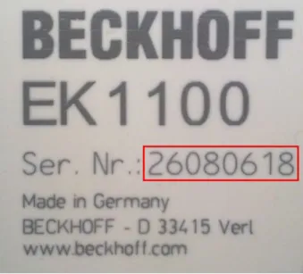
Serial number is the name generally given to the 8-digit number that is printed on the device or attached to it on a sticker. This serial number indicates the as-built status on delivery and thus ambiguously marks a whole production lot.
Structure of the serial number: KK YY FF HH
KK - week of production (CW, calendar week) YY - year of production
FF - firmware version HH - hardware version
Example with ser. no.: 12063A02: 12 - production week 12 06 - production year 2006 3A - firmware version 3A 02 - hardware version 02
Exceptions can occur in the IP67 area , where the following syntax can be used (see respective device documentation):
Syntax: D ww yy x y z u D - prefix designation ww - calendar week yy - year
x - firmware version of the bus PCB y - hardware version of the bus PCB z - firmware version of the I/O PCB u - hardware version of the I/O PCB
Example: D.22081501 calendar week 22 of the year 2008 firmware version of bus PCB: 1 hardware version of bus PCB: 5 firmware version of I/O PCB: 0 (no firmware necessary for this PCB) hardware version of I/O PCB: 1
Unique serial number/ID
Beyond that there are some series in which each individual module has its own unique, sequential serial number.
See also the further documentation in the area • IP67: EtherCAT Box
• Safety: TwinSafe
Examples of markings:
Fig. 1: EL5021 EL terminal, standard IP20 IO device with batch number and revision ID (since 2014/01)
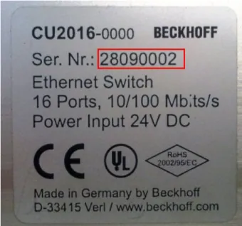
Fig. 3: CU2016 switch with batch number
Fig. 4: EL3202-0020 with batch numbers 26131006 and unique D-number 204418
Fig. 5: EP1258-00001 IP67 EtherCAT Box with batch number 22090101 and serial number 158102
3
Product overview
3.1
Introduction
Fig. 8: EL5101
Interface terminal for incremental encoder
The EL5101-00x0 EtherCAT Terminal is an interface for direct connection of incremental encoders with differential inputs (RS485). A 16-bit counter (in normal operating mode) or a switchable 16/32-bit counter (in enhanced operating mode) with a quadrature decoder and a 16-bit latch (in normal operating mode) or 32-bit latch (in enhanced operating mode) for the zero pulse can be read, set or enabled. Incremental encoders with alarm output can be connected at the negative switching status input of the interface. The measurement of period and frequency is possible. The gate input allows the locking of the counter, alternatively with a high or low level. The latch input is similarly configurable and evaluates high or low levels. The EL5101-0000 can also be used as bidirectional counter on channel A; channel B specifies the count direction.
Through the further development of the EL5101-0000 an enhanced operating mode is available (from firmware 14 / hardware 09 [} 130]), which can be parameterized in the TwinCAT System Manager, depending on the hardware used.
Older EL5101-0000 devices do not support this enhanced operating mode (see Table 1)!
Version from FW/
HW
ESI Functional description
normal operating mode EL5101-0000
03/05 from
EL5101-0000-0000
All basic functions as described above enhanced operating
mode
EL5101-0000
14/09 from
EL5101-0000-1018
Changes to the normal operating mode - Distributed clock support
- Micro-increments - Broken wire detection
- Connection of SingleEnded signals possible
The EL5101-0010 with a resolution of 20 mio. increments/s at 5 MHz and 4-fold evaluation is only applicable for the enhanced operating mode. The inputs can process differential signals according to RS485. The microincrement mode is not available for the EL5101-0010.
The EL5101-00x0 supports distributed clocks in the enhanced operating mode, i.e. the input data can be recorded synchronously with other data that are also linked to Distributed Clock slaves. The accuracy across the system is < 100 ns.
The two operating modes are described separately below, which is why a decision re. the operating mode has to be made during commissioning.
Quick-Links
• Basics communication [} 18]
• Creation of the TwinCAT configuration [} 59]
• Process data and modes - normal operation mode [} 89]
• Process data and modes - enhanced operation mode [} 99]
• Object description and parameterization - normal operation mode [} 93]
• Object description and parameterization - enhanced operation mode [} 106]
3.2
Technology
The EL5101-00x0 incremental encoder interface terminal enables connection of incremental encoders with A/B/C track to the Bus Coupler and the PLC. A 16-bit counter (in normal operating mode) or a switchable 16/32-bit counter (in enhanced operating mode) with a quadrature decoder and a 16-bit latch (in normal operating mode) or 32-bit latch (in enhanced operating mode) can be read, set or enabled. Differential signals based on RS485 are provided as encoder connection. From hardware 09 [} 130] single-ended 5 V signals are possible for the EL5101-0000 based on pull-up resistors.
In addition to the encoder inputs A, B and C, an additional latch input G1 (24 V) and a gate input G2 (24 V) for locking the counter during operation are available.
The terminal is supplied as a 4-fold quadrature decoder with complementary analysis of the sensor signals A, B, C. If the incremental encoder has an alarm output it can be connected to the INPUT 1 status input of the EL5101-00x0. The EL5101-0000 can optionally be operated as a bidirectional counter terminal on channel A.
Through the further development of the EL5101-0000 an enhanced operating mode is available (from firmware 14 / hardware 09 [} 130]), which can be parameterized in the TwinCAT System Manager, depending on the hardware used.
Older EL5101-0000 devices do not support this extended operating mode (see Table 1)!
Version from FW/
HW
ESI Functional description
normal operating mode EL5101-0000
03/05 from
EL5101-0000-0000
All basic functions as described above enhanced operating
mode
EL5101-0000
14/09 from
EL5101-0000-1018
Changes to the normal operating mode - Distributed clock support
- Micro-increments - Broken wire detection
- Connection of SingleEnded signals possible
Table 1: Operating modes EL5101-0000
The EL5101-0010 with a resolution of 20 mio. increments/s at 5 MHz and 4-fold evaluation is only applicable for the enhanced operating mode. The inputs can process differential signals according to RS485. The microincrement mode is not available for the EL5101-0010.
Note
Compatibility in the case of service
An EL5101-0000 designed for and used in enhanced operating mode cannot be replaced with an EL5101-0000 with older hardware version (< 09)! An EL5101-0010 only supports the enhanced operating mode and is not exchange-compatible with an EL5101-0000 (hard-ware version < 09)!
Irrespective of the hardware/firmware version, after integration into a system an EL5101-0000 reports in normal operating mode.
During commissioning the user has to decide with what functionality, i.e. in what operating mode, the EL5101-0000 is to be used. This depends on the required functions and, of course, the hardware version. Hardware older then firmware 14/hardware 09 [} 130], for example, will not support enhanced operating mode functions.
Combination of functions from different operating modes is not possible. Specific settings are described in the following two sections.
Note
Process data monitoring
• WcState: if ≠ 0, this EtherCAT device does not take part in the process data traffic • State: if ≠ 8, the EtherCAT device is not in OP (operational) status
• TxPDO state, SyncError: if ≠ 0, then no valid process data are available, e.g. caused by broken wire
• TxPDO Toggle: if this bit is toggling, a new set of process data is available
EtherCAT cycle time
For the EL5101 a minimum EtherCAT cycle time of >100 µs is recommended. If a faster cycle time is used, the toggling process record TxPDO Toggle should be used to monitor when new process data are supplied by the EL5101.
EL5101 input impedance
The signal source must be able to operate the input impedance of the EL5101 (typically 220 Ω, subject to modification) with adequate voltage levels according to RS485.
Gate/latch input
For gate and latch inputs (24 V) a max. input frequency of 1 MHz is permitted. Subject to modification.
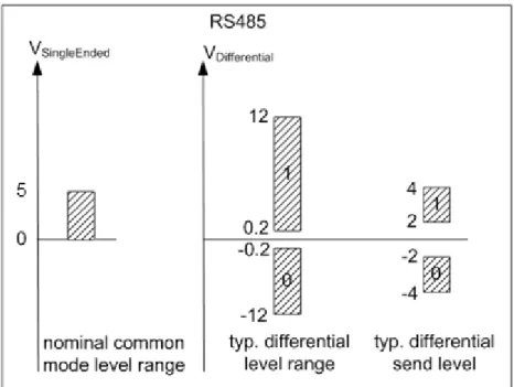
Level on interface
Fig. 9: Level interface RS485
3.3
Technical data
Technical data EL5101-0000 EL5101-0010
Sensor connection A, ¬A, B, ¬B, C, ¬C (RS485 differential inputs) from hardware 09 [} 130]: also single-ended connec-tion (5 V ±20%) possible
A, ¬A, B, ¬B, C, ¬C (RS485 differential inputs)
Additional inputs gate, latch (24 VDC, both max. 1 MHz permitted),
status input (max. 5 VDC, potential-free, switching to negative potential)
Sensor supply 5 VDC
Sensor output current 0.5 A
Counter 16 bit, 16/32 bit switchable
(from firmware 14 / hardware 09 [} 130])
16 bit, 16/32 bit switchable Zero pulse latch 16 bit, 16/32 bit switchable
(from firmware 14 / hardware 09 [} 130])
16 bit, 16/32 bit switchable Limit frequency 1 MHz
(equals 4 million increments with 4-fold evaluation)
5 MHz
(equals 20 million increments with 4-fold evalua-tion)
Quadrature decoder 4-fold evaluation
Distributed Clocks in enhanced operating mode
(from firmware 14 / hardware 09 [} 130])
yes Broken wire detection to
sen-sor
in enhanced operating mode
(from firmware 14 / hardware 09 [} 130])
yes Commands read, set, enable
Power supply for internal E-bus electronics
via the E-bus Current consumption via
E-bus
typ. 130 mA Current consumption from the
power contacts
0.1 A (excluding sensor load current) Electrical isolation 500 V (E-bus/field voltage)
Bit width in process image up to 6 bytes outputs, 22 bytes inputs, depends on parameterization Configuration via TwinCAT System Manager [} 69]
Weight approx. 100 g Permissible ambient
tempera-ture range during operation
-25 °C ... +60 °C (extended temperature range)
0 °C ... +55 °C (according to cULus [} 128] for Canada and the USA) 0 °C ... +55 °C (according to ATEX [} 41], see special conditions [} 41]) Permissible ambient
tempera-ture range during storage
-40 °C ... +85 °C Permissible relative humidity 95%, no condensation
Dimensions (W x H x D) approx. 27 mm x 100 mm x 70 mm (width aligned: 24 mm)
Mounting [} 32] on 35 mm mounting rail conforms to EN 60715 Vibration/shock resistance conforms to EN 60068-2-6 / EN 60068-2-27,
see also installation instructions [} 34] for enhanced mechanical load capacity
conforms to EN 60068-2-6 / EN 60068-2-27
EMC immunity/emission conforms to EN 61000-6-2 / EN 61000-6-4 Protection class IP20
Installation position variable Approval CE
ATEX [} 41] cULus [} 128]
3.4
Start
For commissioning:
• mount the EL5101 as described in the chapter Mounting and wiring [} 32]
4
Basics communication
4.1
EtherCAT basics
Please refer to the chapter EtherCAT System Documentation for the EtherCAT fieldbus basics.
4.2
EtherCAT cabling – wire-bound
The cable length between two EtherCAT devices must not exceed 100 m. This results from the FastEthernet technology, which, above all for reasons of signal attenuation over the length of the cable, allows a maximum link length of 5 + 90 + 5 m if cables with appropriate properties are used. See also the Design
recommendations for the infrastructure for EtherCAT/Ethernet.
Cables and connectors
For connecting EtherCAT devices only Ethernet connections (cables + plugs) that meet the requirements of at least category 5 (CAt5) according to EN 50173 or ISO/IEC 11801 should be used. EtherCAT uses 4 wires for signal transfer.
EtherCAT uses RJ45 plug connectors, for example. The pin assignment is compatible with the Ethernet standard (ISO/IEC 8802-3).
Pin Color of conductor Signal Description
1 yellow TD + Transmission Data +
2 orange TD - Transmission Data
-3 white RD + Receiver Data +
6 blue RD - Receiver Data
-Due to automatic cable detection (auto-crossing) symmetric (1:1) or cross-over cables can be used between EtherCAT devices from Beckhoff.
Note
Recommended cables
Suitable cables for the connection of EtherCAT devices can be found on the Beckhoff web-site!
E-Bus supply
A bus coupler can supply the EL terminals added to it with the E-bus system voltage of 5 V; a coupler is thereby loadable up to 2A as a rule (see details in respective device documentation).
Information on how much current each EL terminal requires from the E-bus supply is available online and in the catalogue. If the added terminals require more current than the coupler can supply, then power feed terminals (e.g. EL9410) must be inserted at appropriate places in the terminal strand.
The pre-calculated theoretical maximum E-bus current is displayed in the TwinCAT System Manager. A shortfall is marked by a negative total amount and an exclamation mark; a power feed terminal is to be placed before such a position.
Fig. 10: System manager current calculation
Attention
Caution! Malfunction possible!
The same ground potential must be used for the E-Bus supply of all EtherCAT terminals in a terminal block!
4.3
General notes for setting the watchdog
ELxxxx terminals are equipped with a safety feature (watchdog) that switches off the outputs after a specifiable time e.g. in the event of an interruption of the process data traffic, depending on the device and settings, e.g. in OFF state.
The EtherCAT slave controller (ESC) in the EL2xxx terminals features 2 watchdogs: • SM watchdog (default: 100 ms)
• PDI watchdog (default: 100 ms)
SM watchdog (SyncManager Watchdog)
The SyncManager watchdog is reset after each successful EtherCAT process data communication with the terminal. If no EtherCAT process data communication takes place with the terminal for longer than the set and activated SM watchdog time, e.g. in the event of a line interruption, the watchdog is triggered and the outputs are set to FALSE. The OP state of the terminal is unaffected. The watchdog is only reset after a successful EtherCAT process data access. Set the monitoring time as described below.
The SyncManager watchdog monitors correct and timely process data communication with the ESC from the EtherCAT side.
PDI watchdog (Process Data Watchdog)
If no PDI communication with the EtherCAT slave controller (ESC) takes place for longer than the set and activated PDI watchdog time, this watchdog is triggered.
PDI (Process Data Interface) is the internal interface between the ESC and local processors in the EtherCAT slave, for example. The PDI watchdog can be used to monitor this communication for failure.
The PDI watchdog monitors correct and timely process data communication with the ESC from the application side.
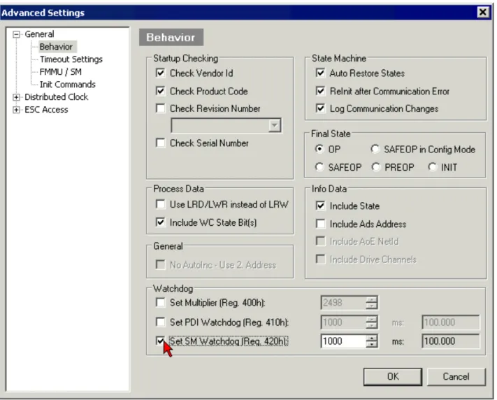
The settings of the SM- and PDI-watchdog must be done for each slave separately in the TwinCAT System Manager.
Fig. 11: EtherCAT tab -> Advanced Settings -> Behavior -> Watchdog
Notes:
• the multiplier is valid for both watchdogs.
• each watchdog has its own timer setting, the outcome of this in summary with the multiplier is a resulting time.
• Important: the multiplier/timer setting is only loaded into the slave at the start up, if the checkbox is activated.
If the checkbox is not activated, nothing is downloaded and the ESC settings remain unchanged.
Multiplier
Multiplier
Both watchdogs receive their pulses from the local terminal cycle, divided by the watchdog multiplier: 1/25 MHz * (watchdog multiplier + 2) = 100 µs (for default setting of 2498 for the multiplier)
The standard setting of 1000 for the SM watchdog corresponds to a release time of 100 ms.
The value in multiplier + 2 corresponds to the number of basic 40 ns ticks representing a watchdog tick. The multiplier can be modified in order to adjust the watchdog time over a larger range.
Example "Set SM watchdog"
This checkbox enables manual setting of the watchdog times. If the outputs are set and the EtherCAT communication is interrupted, the SM watchdog is triggered after the set time and the outputs are erased. This setting can be used for adapting a terminal to a slower EtherCAT master or long cycle times. The default SM watchdog setting is 100 ms. The setting range is 0..65535. Together with a multiplier with a range of 1..65535 this covers a watchdog period between 0..~170 seconds.
Calculation
Multiplier = 2498 → watchdog base time = 1 25 MHz * (2498 + 2) = 0.0001 seconds = 100 µs SM watchdog = 10000 → 10000 * 100 µs = 1 second watchdog monitoring time
CAUTION
CAUTION! Undefined state possible!
The function for switching off of the SM watchdog via SM watchdog = 0 is only imple-mented in terminals from version -0016. In previous versions this operating mode should not be used.
CAUTION
CAUTION! Damage of devices and undefined state possible!
If the SM watchdog is activated and a value of 0 is entered the watchdog switches off com-pletely. This is the deactivation of the watchdog! Set outputs are NOT set in a safe state, if the communication is interrupted.
Note
Outputs in SAFEOP state
The default set watchdog monitoring sets the outputs of the module in a safe state - pending on the settings in SAFEOP and OP - e.g. in OFF state. If this is prevented by de-activation of the watchdog monitoring in the module, the outputs can be switched or set also in the SAFEOP state.
4.4
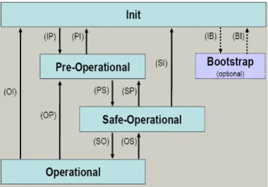
EtherCAT State Machine
The state of the EtherCAT slave is controlled via the EtherCAT State Machine (ESM). Depending upon the state, different functions are accessible or executable in the EtherCAT slave. Specific commands must be sent by the EtherCAT master to the device in each state, particularly during the bootup of the slave. A distinction is made between the following states:
• Init
• Pre-Operational • Safe-Operational and • Operational
• Boot
Fig. 12: States of the EtherCAT State Machine
Init
After switch-on the EtherCAT slave in the Init state. No mailbox or process data communication is possible. The EtherCAT master initializes sync manager channels 0 and 1 for mailbox communication.
Pre-Operational (Pre-Op)
During the transition between Init and Pre-Op the EtherCAT slave checks whether the mailbox was initialized correctly.
In Pre-Op state mailbox communication is possible, but not process data communication. The EtherCAT master initializes the sync manager channels for process data (from sync manager channel 2), the FMMU channels and, if the slave supports configurable mapping, PDO mapping or the sync manager PDO
assignment. In this state the settings for the process data transfer and perhaps terminal-specific parameters that may differ from the default settings are also transferred.
Safe-Operational (Safe-Op)
During transition between Pre-Op and Safe-Op the EtherCAT slave checks whether the sync manager channels for process data communication and, if required, the distributed clocks settings are correct. Before it acknowledges the change of state, the EtherCAT slave copies current input data into the associated DP-RAM areas of the EtherCAT slave controller (ECSC).
In Safe-Op state mailbox and process data communication is possible, although the slave keeps its outputs in a safe state, while the input data are updated cyclically.
Note
Outputs in SAFEOP state
The default set watchdog monitoring sets the outputs of the module in a safe state - pending on the settings in SAFEOP and OP - e.g. in OFF state. If this is prevented by de-activation of the watchdog monitoring in the module, the outputs can be switched or set also in the SAFEOP state.
Operational (Op)
Before the EtherCAT master switches the EtherCAT slave from Safe-Op to Op it must transfer valid output data.
In the Op state the slave copies the output data of the masters to its outputs. Process data and mailbox communication is possible.
Boot
In the Boot state the slave firmware can be updated. The Boot state can only be reached via the Init state. In the Boot state mailbox communication via the file access over EtherCAT (FoE) protocol is possible, but no other mailbox communication and no process data communication.
4.5
CoE Interface
General description
The CoE interface (CANopen over EtherCAT) is used for parameter management of EtherCAT devices. EtherCAT slaves or the EtherCAT master manage fixed (read only) or variable parameters which they require for operation, diagnostics or commissioning.
CoE parameters are arranged in a table hierarchy. In principle, the user has read access via the fieldbus. The EtherCAT master (TwinCAT System Manager) can access the local CoE lists of the slaves via EtherCAT in read or write mode, depending on the attributes.
Different CoE parameter types are possible, including string (text), integer numbers, Boolean values or larger byte fields. They can be used to describe a wide range of features. Examples of such parameters include manufacturer ID, serial number, process data settings, device name, calibration values for analog
measurement or passwords.
The order is specified in 2 levels via hexadecimal numbering: (main)index, followed by subindex. The value ranges are
• Index: 0x0000 …0xFFFF (0...65535dez) • SubIndex: 0x00…0xFF (0...255dez)
A parameter localized in this way is normally written as 0x8010:07, with preceding "x" to identify the hexadecimal numerical range and a colon between index and subindex.
The relevant ranges for EtherCAT fieldbus users are:
• 0x1000: This is where fixed identity information for the device is stored, including name, manufacturer, serial number etc., plus information about the current and available process data configurations. • 0x8000: This is where the operational and functional parameters for all channels are stored, such as
filter settings or output frequency. Other important ranges are:
• 0x4000: In some EtherCAT devices the channel parameters are stored here (as an alternative to the 0x8000 range).
• 0x6000: Input PDOs ("input" from the perspective of the EtherCAT master) • 0x7000: Output PDOs ("output" from the perspective of the EtherCAT master)
Note
Availability
Not every EtherCAT device must have a CoE list. Simple I/O modules without dedicated processor usually have no variable parameters and therefore no CoE list.
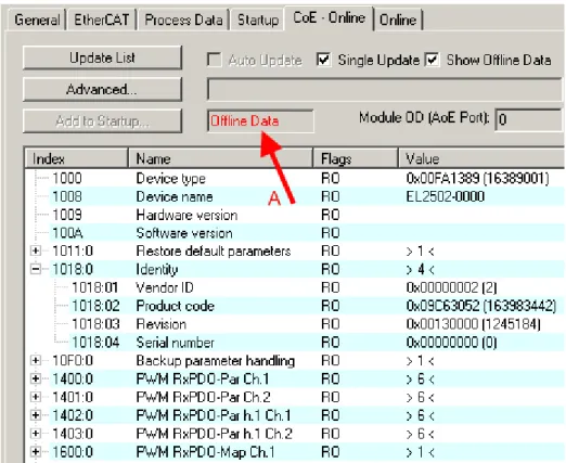
If a device has a CoE list, it is shown in the TwinCAT System Manager as a separate tab with a listing of the elements:
Fig. 13: "CoE Online " tab
The figure above shows the CoE objects available in device "EL2502", ranging from 0x1000 to 0x1600. The subindices for 0x1018 are expanded.
Data management
Some parameters, particularly the setting parameters of the slave, are configurable and writeable. This can be done in write or read mode
• via the System Manager (Fig. "CoE Online " tab) by clicking
This is useful for commissioning of the system/slaves. Click on the row of the index to be parameterised and enter a value in the "SetValue" dialog.
• from the control system/PLC via ADS, e.g. through blocks from the TcEtherCAT.lib library This is recommended for modifications while the system is running or if no System Manager or operating staff are available.
If slave CoE parameters are modified online, Beckhoff devices store any changes in a fail-safe manner in the EEPROM, i.e. the modified CoE parameters are still available after a restart. The situation may be different with other manufacturers.
An EEPROM is subject to a limited lifetime with respect to write operations. From typically 100,000 write operations onwards it can no longer be guaranteed that new (changed) data are reliably saved or are still readable. This is irrelevant for normal commissioning. However, if CoE parameters are continuously changed via ADS at machine runtime, it is quite possible for the lifetime limit to be reached. Support for the
NoCoeStorage function, which suppresses the saving of changed CoE values, depends on the firmware version.
Note
Data management
ü Data management function
a) If the function is supported: the function is activated by entering the code word 0x12345678 once in CoE 0xF008 and remains active as long as the code word is not changed. After switching the device on it is then inactive. Changed CoE values are not saved in the EEPROM and can thus be changed any number of times.
Note
Startup list
Changes in the local CoE list of the terminal are lost if the terminal is replaced. If a terminal is replaced with a new Beckhoff terminal, it will have the default settings. It is therefore ad-visable to link all changes in the CoE list of an EtherCAT slave with the Startup list of the slave, which is processed whenever the EtherCAT fieldbus is started. In this way a replace-ment EtherCAT slave can automatically be parameterised with the specifications of the user.
If EtherCAT slaves are used which are unable to store local CoE values permanently, the Startup list must be used.
Recommended approach for manual modification of CoE parameters
• Make the required change in the System ManagerThe values are stored locally in the EtherCAT slave
• If the value is to be stored permanently, enter it in the Startup list. The order of the Startup entries is usually irrelevant.
Fig. 14: Startup list in the TwinCAT System Manager
The Startup list may already contain values that were configured by the System Manager based on the ESI specifications. Additional application-specific entries can be created.
Online/offline list
While working with the TwinCAT System Manager, a distinction has to be made whether the EtherCAT device is "available", i.e. switched on and linked via EtherCAT and therefore online, or whether a configuration is created offline without connected slaves.
In both cases a CoE list as shown in Fig. “’CoE online’ tab” is displayed. The connectivity is shown as offline/ online.
• If the slave is offline
- The offline list from the ESI file is displayed. In this case modifications are not meaningful or possible. - The configured status is shown under Identity.
- No firmware or hardware version is displayed, since these are features of the physical device. - Offline is shown in red.
Fig. 15: Offline list
• If the slave is online
- The actual current slave list is read. This may take several seconds, depending on the size and cycle time. - The actual identity is displayed
- The firmware and hardware version of the equipment according to the electronic information is displayed - Online is shown in green.
Fig. 16: Online list
Channel-based order
The CoE list is available in EtherCAT devices that usually feature several functionally equivalent channels. For example, a 4-channel analog 0..10 V input terminal also has 4 logical channels and therefore 4 identical sets of parameter data for the channels. In order to avoid having to list each channel in the documentation,
In the CoE system 16 indices, each with 255 subindices, are generally sufficient for representing all channel parameters. The channel-based order is therefore arranged in 16dec/10hex steps. The parameter range 0x8000 exemplifies this:
• Channel 0: parameter range 0x8000:00 ... 0x800F:255 • Channel 1: parameter range 0x8010:00 ... 0x801F:255 • Channel 2: parameter range 0x8020:00 ... 0x802F:255 • ...
This is generally written as 0x80n0.
Detailed information on the CoE interface can be found in the EtherCAT system documentation on the Beckhoff website.
4.6
DC settings
Distributed Clocks (DC)
Note
EtherCAT and Distributed Clocks
A basic introduction into EtherCAT and distributed clocks is available for download from the Beckhoff website: the “Distributed clocks system description”.
The incremental encoder terminals support the distributed clocks function (EL5101: from Hardware 09 / Firmware 14; EL5151 from Hardware 01 / Firmware 05). In order for the EL51xx to be able to make the current counter value available in the designated process data in time before the arrival of the querying EtherCAT datagram, a suitable signal must be generated cyclically within the terminal. This signal can be triggered in the EL51xx through two events: the SyncManager (SM) and the distributed clock (DC). Under operation mode selection the following options are available (see Fig. 1)
Fig. 17: “DC” tab (Distributed Clocks)
• FreeRun/SM-Synchron
The SynManager event occurs when an EtherCAT frame successfully exchanges process data with the EL51xx. Frame-triggered, the current counter value is thus cyclically determined, but with the low temporal jitter of the Ethernet frame. In this mode an Ethernet frame triggers the process data provision for the next retrieving frame. This generally only occurs after 1x cycle time.
• DC Synchronous
In DC mode, a counter reading is triggered by the integrated DC unit with a constant cycle, usually in synchrony with the bus cycle, although with a constant shift (phase, shift time, offset). Sampling is significantly more uniform (synchronization accuracy: 100 ns), which means a higher-level control algorithm can be supplied with higher-quality position data, for example. In the EL51xx the trigger is the SYNC0 signal, which is set like an output component in “DC-synchron” mode. See Distributed Clocks system description.
The DC modes enable the start time of the process data provision to be offset by an offset value (shift value). This offset value can only by set on EtherCAT startup and can then no longer be changed
SYNC signal can either occur before or after the expect frame pass-through time: For input terminals the SYNC signal is generated before the frame, in order to make current input data available for forwarding. For output terminals the SYNC signal is set to a time after the frame has passed through, so that the just supplied data are output immediately. Since only one of the two modes is possible, the user can set the optimum mode for his application.
"DC Synchronous" corresponds to the output module configuration. The local SYNC event is triggered shortly after the EtherCAT frame has passed.
• DC-Synchron (input based)
In the “DC-Synchronous (input based)” mode this EL51xx is assigned to the group of input modules and the shift time (see Fig. Advanced Distributed Clock (DC) settings, EL51xx terminal) is calculated accordingly.
When “DC-Synchronous” operating mode is activated, TwinCAT selects settings that ensure reliable operation of the EL51xx and the acquisition of current position data. This means that determination of the current counter value is started by the SYNC0 signal at highly constant intervals and in the operating mode “DC-Synchronous (input based)” in good time – i.e. with an adequate safety buffer – before the retrieving EtherCAT datagram.
Note
Duration of the process data provision in the EL51x1
The EL5101 (from Hardware 09 / Firmware 14) or the EL5151 (from Hardware 01/ Firmware 05) requires approx. 80 µs after the SYNC event to determine the position data and provide them for retrieval. This value depends on the configuration and parameteriza-tion. The actual current duration can be read using the internal DC functions, see CoE set-ting in 1C32:08 and the result in 1C32:05.
If necessary, the SYNC0 signal can be shifted along the time axis to the right/later or left/earlier in associated dialogs by specifying a “User defined Shift Time”, see Fig. Advanced Distributed Clock (DC) settings, EL51xx terminal.
• A right-shift (positive shift value) will delay the counter value query, which means the position value becomes more current from the PLC perspective. However, this increases the risk that the position determination may not be finished in time before the arrival of EtherCAT frame, so that no current position value is available in this cycle.
• A left-shift (negative shift value) means the counter value will be queried earlier, resulting in older position values, with an associated increase in the safety buffer before the arrival of the EtherCAT datagram. This setting may be useful in systems with high real-time jitter, if no Industrial PCs from Beckhoff are used for control purposes, for example.
Attention
Attention! Risk of device damage!
The mentioned notes and information should be used advisedly. The EtherCAT master au-tomatically allocates SYNC0 and SYNC1 settings that support reliable and timely process data acquisition. User intervention at this point may lead to undesired behavior. If these set-tings are changed in the System Manager, no plausibility checks are carried out on the soft-ware side. Correct function of the terminal with all conceivable setting options cannot be guaranteed.
Default setting
The cyclic read of the inputs is triggered by the SYNC0 pulse (interrupt) from the DC in the EL51xx. The EtherCAT master sets the Sync Unit Cycle time value to the PLC cycle time and therefore the EtherCAT cycle time as standard. See Fig. Advanced Distributed Clock (DC) settings, EL51xx terminal: 4000µs = 4 ms, as TwinCAT is in configuration mode.
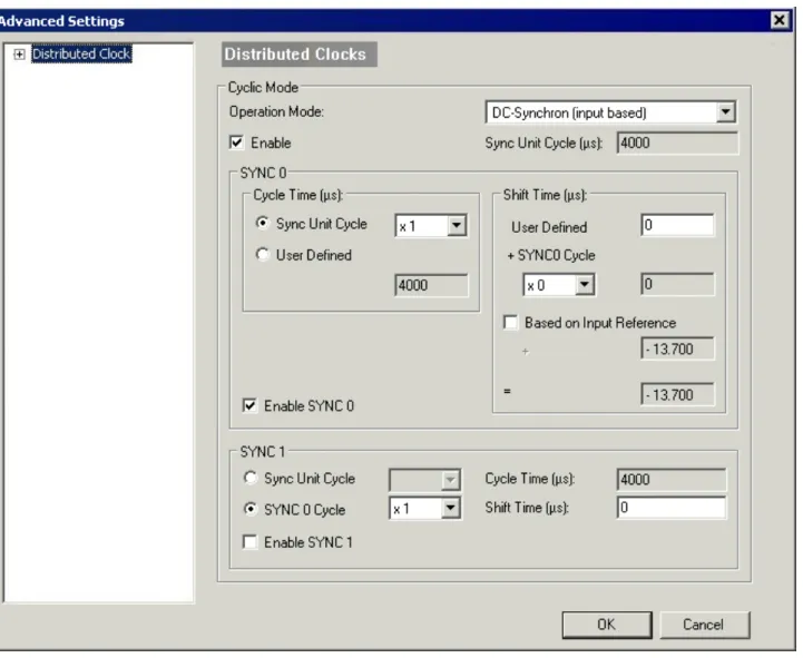
EL51xx DC settings
Fig. 18: Advanced Distributed Clock (DC) settings, EL51xx terminal
• SYNC0
Sync unit cycle: a multiple of the bus cycle time. The counter value is periodically determined at this interval (in µs).
• User-defined
Arbitrary number up to 232 ns ≈ 4.3 secs. Decimal point values are possible. • Shift Time
The Shift Time can be used to shift the SYNC0 pulse for this EL51xx relative to other terminals and the global SYNC pulse in nanosecond steps. If the data of several EL51xx terminals are to be read
simultaneously, the same value must be entered here. • Based on input reference
If this option is activated an additional Input Shift is added to the configurable terminal-specific SYNC0 shift (user-defined). This value is calculated and made available by the EtherCAT master (SysMan/ EtherCAT device/EtherCAT tab/Advanced Settings/Distributed Clocks/Input Shift Time/, see Fig.
EtherCAT Master, EtherCAT tab, Advanced Settings + EtherCAT Master, Advanced Settings,
Distributed Clock). In this way all input terminals in the system (EL1xxx, EL3xxx and appropriately set ELxxxx such as the EL51xx) read their inputs as close as possible to the time of the EtherCAT frame that will fetch them, thereby supplying the most recent possible input data to the controller. In input-based mode this value is taken into account automatically.
• Enable SYNC0
• SYNC1
Additional SYNC pulse, derived from SYNC0 or from the DC itself. Not required by the EL51xx.
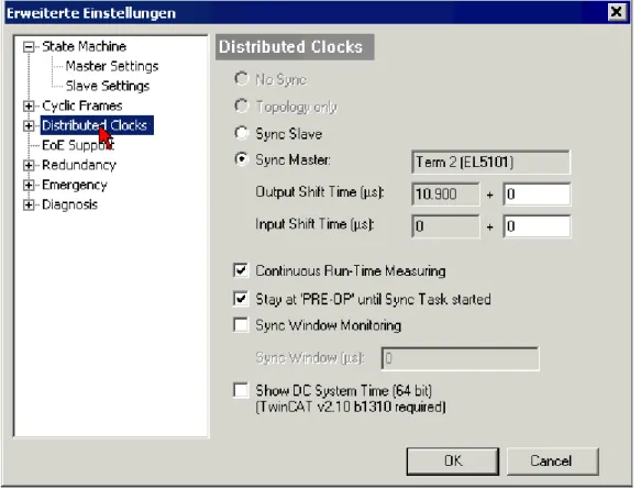
DC settings for EtherCAT master
Higher-level distributed clock parameters can be modified under advanced settings for the EtherCAT master. Refer also to the basic introduction to the topic of EtherCAT and Distributed Clocks; download: the
“Distributed clocks system description”.
Fig. 19: EtherCAT Master, EtherCAT tab, Advanced Settings
5
Mounting and wiring
5.1
Installation on mounting rails
WARNING
Risk of electric shock and damage of device!
Bring the bus terminal system into a safe, powered down state before starting installation, disassembly or wiring of the Bus Terminals!
Assembly
Fig. 22: Attaching on mounting rail
The Bus Coupler and Bus Terminals are attached to commercially available 35 mm mounting rails (DIN rails according to EN 60715) by applying slight pressure:
1. First attach the Fieldbus Coupler to the mounting rail.
2. The Bus Terminals are now attached on the right-hand side of the Fieldbus Coupler. Join the components with tongue and groove and push the terminals against the mounting rail, until the lock clicks onto the mounting rail.
If the Terminals are clipped onto the mounting rail first and then pushed together without tongue and groove, the connection will not be operational! When correctly assembled, no significant gap should be visible between the housings.
Note
Fixing of mounting rails
The locking mechanism of the terminals and couplers extends to the profile of the mounting rail. At the installation, the locking mechanism of the components must not come into con-flict with the fixing bolts of the mounting rail. To mount the mounting rails with a height of 7.5 mm under the terminals and couplers, you should use flat mounting connections (e.g. countersunk screws or blind rivets).
Disassembly
Fig. 23: Disassembling of terminal
Each terminal is secured by a lock on the mounting rail, which must be released for disassembly:
1. Pull the terminal by its orange-colored lugs approximately 1 cm away from the mounting rail. In doing so for this terminal the mounting rail lock is released automatically and you can pull the terminal out of the bus terminal block easily without excessive force.
2. Grasp the released terminal with thumb and index finger simultaneous at the upper and lower grooved housing surfaces and pull the terminal out of the bus terminal block.
Connections within a bus terminal block
The electric connections between the Bus Coupler and the Bus Terminals are automatically realized by joining the components:
• The six spring contacts of the K-Bus/E-Bus deal with the transfer of the data and the supply of the Bus Terminal electronics.
• The power contacts deal with the supply for the field electronics and thus represent a supply rail within the bus terminal block. The power contacts are supplied via terminals on the Bus Coupler (up to 24 V) or for higher voltages via power feed terminals.
Note
Power Contacts
During the design of a bus terminal block, the pin assignment of the individual Bus Termi-nals must be taken account of, since some types (e.g. analog Bus TermiTermi-nals or digital 4-channel Bus Terminals) do not or not fully loop through the power contacts. Power Feed Terminals (KL91xx, KL92xx or EL91xx, EL92xx) interrupt the power contacts and thus rep-resent the start of a new supply rail.
PE power contact
The power contact labeled PE can be used as a protective earth. For safety reasons this contact mates first when plugging together, and can ground short-circuit currents of up to 125 A.
Fig. 24: Power contact on left side
Attention
Possible damage of the device
Note that, for reasons of electromagnetic compatibility, the PE contacts are capacitatively coupled to the mounting rail. This may lead to incorrect results during insulation testing or to damage on the terminal (e.g. disruptive discharge to the PE line during insulation testing of a consumer with a nominal voltage of 230 V). For insulation testing, disconnect the PE supply line at the Bus Coupler or the Power Feed Terminal! In order to decouple further feed points for testing, these Power Feed Terminals can be released and pulled at least 10 mm from the group of terminals.
WARNING
Risk of electric shock!
The PE power contact must not be used for other potentials!
5.2
Installation instructions for enhanced mechanical load
capacity
WARNING
Risk of injury through electric shock and damage to the device!
Bring the Bus Terminal system into a safe, de-energized state before starting mounting, disassembly or wiring of the Bus Terminals!
Additional checks
The terminals have undergone the following additional tests:
Verification Explanation
Vibration 10 frequency runs in 3 axes
6 Hz < f < 60 Hz displacement 0.35 mm, constant amplitude 60.1 Hz < f < 500 Hz acceleration 5 g, constant amplitude Shocks 1000 shocks in each direction, in 3 axes
Additional installation instructions
For terminals with enhanced mechanical load capacity, the following additional installation instructions apply: • Any installation position is permitted
• Use a mounting rail according to EN 60715 TH35-15
• Fix the terminal segment on both sides of the mounting rail with a mechanical fixture, e.g. an earth terminal or reinforced end clamp
• The maximum total extension of the terminal segment (without coupler) is: 64 terminals (12 mm mounting with) or 32 terminals (24 mm mounting with)
• Avoid deformation, twisting, crushing and bending of the mounting rail during edging and installation of the rail
• The mounting points of the mounting rail must be set at 5 cm intervals • Use countersunk head screws to fasten the mounting rail
• The free length between the strain relief and the wire connection should be kept as short as possible. A distance of approx. 10 cm should be maintained to the cable duct.
5.3
Connection system
WARNING
Risk of electric shock and damage of device!
Bring the bus terminal system into a safe, powered down state before starting installation, disassembly or wiring of the Bus Terminals!
Overview
The Bus Terminal system offers different connection options for optimum adaptation to the respective application:
• The terminals of KLxxxx and ELxxxx series with standard wiring include electronics and connection level in a single enclosure.
• The terminals of KSxxxx and ESxxxx series feature a pluggable connection level and enable steady wiring while replacing.
• The High Density Terminals (HD Terminals) include electronics and connection level in a single enclosure and have advanced packaging density.
Standard wiring
Fig. 25: Standard wiring
The terminals of KLxxxx and ELxxxx series have been tried and tested for years. They feature integrated screwless spring force technology for fast and simple assembly.
Pluggable wiring
Fig. 26: Pluggable wiring
The terminals of KSxxxx and ESxxxx series feature a pluggable connection level.
The assembly and wiring procedure for the KS series is the same as for the KLxxxx and ELxxxx series. The KS/ES series terminals enable the complete wiring to be removed as a plug connector from the top of the housing for servicing.
The lower section can be removed from the terminal block by pulling the unlocking tab.
Insert the new component and plug in the connector with the wiring. This reduces the installation time and eliminates the risk of wires being mixed up.
The familiar dimensions of the terminal only had to be changed slightly. The new connector adds about 3 mm. The maximum height of the terminal remains unchanged.
A tab for strain relief of the cable simplifies assembly in many applications and prevents tangling of individual connection wires when the connector is removed.
Conductor cross sections between 0.08 mm2 and 2.5 mm2 can continue to be used with the proven spring force technology.
The overview and nomenclature of the product names for KSxxxx and ESxxxx series has been retained as known from KLxxxx and ELxxxx series.
High Density Terminals (HD Terminals)
Fig. 27: High Density Terminals
The Bus Terminals from these series with 16 connection points are distinguished by a particularly compact design, as the packaging density is twice as large as that of the standard 12 mm Bus Terminals. Massive conductors and conductors with a wire end sleeve can be inserted directly into the spring loaded terminal point without tools.
Note
Wiring HD Terminals
The High Density (HD) Terminals of the KLx8xx and ELx8xx series doesn't support steady wiring.
Ultrasonically "bonded" (ultrasonically welded) conductors
Note
Ultrasonically “bonded" conductors
It is also possible to connect the Standard and High Density Terminals with ultrasonically "bonded" (ultrasonically welded) conductors. In this case, please note the tables concern-ing the wire-size width [} 37] below!
Wiring
Terminals for standard wiring ELxxxx / KLxxxx and terminals for steady wiring
ESxxxx / KSxxxx
Fig. 28: Mounting a cable on a terminal connection
Up to eight connections enable the connection of solid or finely stranded cables to the Bus Terminals. The terminals are implemented in spring force technology. Connect the cables as follows:
1. Open a spring-loaded terminal by slightly pushing with a screwdriver or a rod into the square opening above the terminal.
2. The wire can now be inserted into the round terminal opening without any force.
3. The terminal closes automatically when the pressure is released, holding the wire securely and permanently.
Terminal housing ELxxxx, KLxxxx ESxxxx, KSxxxx
Wire size width 0.08 ... 2,5 mm2
0.08 ... 2.5 mm2
Wire stripping length 8 ... 9 mm 9 ... 10 mm
High Density Terminals ELx8xx, KLx8xx (HD)
The conductors of the HD Terminals are connected without tools for single-wire conductors using the direct plug-in technique, i.e. after stripping the wire is simply plugged into the contact point. The cables are released, as usual, using the contact release with the aid of a screwdriver. See the following table for the suitable wire size width.
Terminal housing High Density Housing
Wire size width (conductors with a wire end sleeve) 0.14... 0.75 mm2
Wire size width (single core wires) 0.08 ... 1.5 mm2
Wire size width (fine-wire conductors) 0.25 ... 1.5 mm2
Wire size width (ultrasonically “bonded" conductors) only 1.5 mm2 (see notice [} 36]!)
Shielding
Note
Shielding
Analog sensors and actors should always be connected with shielded, twisted paired wires.
5.4
Installation positions
Attention
Constraints regarding installation position and operating temperature range
Please refer to the technical data for a terminal to ascertain whether any restrictions re-garding the installation position and/or the operating temperature range have been speci-fied. When installing high power dissipation terminals ensure that an adequate spacing is maintained between other components above and below the terminal in order to guarantee adequate ventilation!
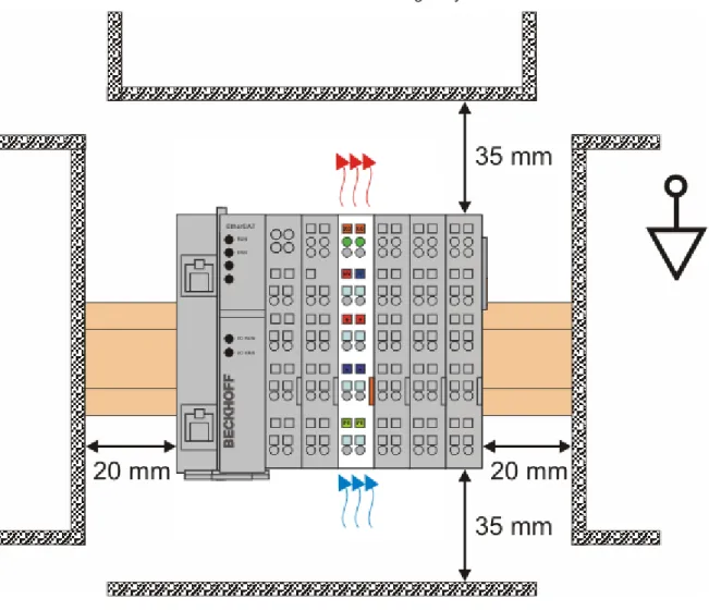
Optimum installation position (standard)
The optimum installation position requires the mounting rail to be installed horizontally and the connection surfaces of the EL/KL terminals to face forward (see Fig. “Recommended distances for standard installation position”). The terminals are ventilated from below, which enables optimum cooling of the electronics through convection. "From below" is relative to the acceleration of gravity.
Fig. 29: Recommended distances for standard installation position
Compliance with the distances shown in Fig. “Recommended distances for standard installation position” is recommended.
Other installation positions
All other installation positions are characterized by different spatial arrangement of the mounting rail - see Fig “Other installation positions”.
The minimum distances to ambient specified above also apply to these installation positions.
Fig. 30: Other installation positions
5.5
Mounting of Passive Terminals
Note
Hint for mounting passive terminals
EtherCAT Bus Terminals (ELxxxx / ESxxxx), which do not take an active part in data trans-fer within the bus terminal block are so called Passive Terminals. The Passive Terminals have no current consumption out of the E-Bus To ensure an optimal data transfer, you must not directly string together more than 2 Passive Terminals!
Examples for mounting passive terminals (highlighted)
Fig. 31: Correct configuration
5.6
ATEX - Special conditions
WARNING
Observe the special conditions for the intended use of Beckhoff fieldbus components in potentially explosive areas (directive 94/9/EU)!
ü Conditions
a) The certified components are to be installed in a suitable housing that guarantees a protection class of at least IP54 in accordance with EN 60529! The environmental con-ditions during use are thereby to be taken into account!
b) If the temperatures during rated operation are higher than 70°C at the feed-in points of cables, lines or pipes, or higher than 80°C at the wire branching points, then cables must be selected whose temperature data correspond to the actual measured tempera-ture values!
c) Observe the permissible ambient temperature range of 0 - 55°C for the use of Beckhoff fieldbus components in potentially explosive areas!
d) Measures must be taken to protect against the rated operating voltage being exceeded by more than 40% due to short-term interference voltages!
e) The individual terminals may only be unplugged or removed from the Bus Terminal sys-tem if the supply voltage has been switched off or if a non-explosive atmosphere is en-sured!
f) The connections of the certified components may only be connected or disconnected if the supply voltage has been switched off or if a non-explosive atmosphere is ensured! g) The fuses of the KL92xx power feed terminals may only be exchanged if the supply
voltage has been switched off or if a non-explosive atmosphere is ensured!
h) Address selectors and ID switches may only be adjusted if the supply voltage has been switched off or if a non-explosive atmosphere is ensured!
Standards
The fundamental health and safety requirements are fulfilled by compliance with the following standards: • EN 60079-0: 2006
Marking
The Beckhoff fieldbus components certified for potentially explosive areas bear one of the following markings:
II 3 G Ex nA II T4 KEMA 10ATEX0075 X Ta: 0 - 55°C
or
II 3 G Ex nA nC IIC T4 KEMA 10ATEX0075 X Ta: 0 - 55°C
Serial number
The Beckhoff fieldbus components bear a serial number that is structured as follows: WW YY FF HH
WW - week of production (CW, calendar week) YY - year of production
FF - firmware version HH - hardware version
Example with ser. no.: 35 04 1B 01: 35 - week of production 35
04 - year of production 2004 1B - firmware version 1B 01 - hardware version 01
5.7
LEDs and connection
Fig. 33: EL5101
Connection
Terminal point No. Comment
A 1 Encoder input A
B 2 Encoder input B
C 3 Encoder input C
Latch 24 V 4 Latch input
¬A 5 Encoder input A
¬B 6 Encoder input B
¬C 7 Encoder input C
Gate 24 V 8 Gate input
Ue = +5 V 1' +5 V encoder supply
+24 V 2' +24 V (internally connected to terminal point 6' and positive power contact) 0 V 3' 0 V (internally connected to terminal point 7' and negative power contact) Input 1 4' Status input 1
Alarm input from rotary encoder. Internally connected to 5 V via pull-up. Switching to negative potential, i.e. connection to GND leads to error bit and LED display. If externally supplied (not recommended) 5 V max. against GND is permitted.
Uo = 0 V 5' 0 V encoder supply
+24 V 6' +24 V (internally connected to terminal point 2' and positive power contact) 0 V 7' 0 V (internally connected to terminal point 3' and negative power contact)
LEDs
LED Color Meaning
INPUT A, B, C green indicates TRUE level
INPUT 1 red is lit, if INPUT 1 is connected to GND
[INPUT 1 is connected to an internal 5 V HIGH level though internal pull-up (default)]
LATCH green is lit, if a signal (+24 V) is connected to the latch input GATE green is lit, if a signal (+24 V) is connected to the gate input RUN green This LED indicates the terminal's operating state:
off State of the EtherCAT State Machine [} 21]: INIT = initialization of the terminal or BOOTSTRAP = function for firmware updates [} 131] of the terminal
flashing State of the EtherCAT State Machine: PREOP = function for mailbox communication and different standard-settings set
single flash
State of the EtherCAT State Machine: SAFEOP = verification of the Sync Manager [} 69] channels and the distributed clocks.
Outputs remain in safe state
on State of the EtherCAT State Machine: OP = normal operating state; mailbox and process data communication is possible
6
Commissioning
6.1
TwinCAT 2.1x
6.1.1
Installation of the TwinCAT real-time driver
In order to assign real-time capability to a standard Ethernet port of an IPC controller, the Beckhoff real-time driver has to be installed on this port under Windows.
This can be done in several ways. One option is described here.
In the System Manager call up the TwinCAT overview of the local network interfaces via Options -> Show Real Time Ethernet Compatible Devices.
Fig. 34: System Manager option
Fig. 35: Overview of network interfaces
Interfaces listed under “Compatible devices” can be assigned a driver via the “Install” button. A driver should only be installed on compatible devices.
A Windows warning regarding the unsigned driver can be ignored.
Alternatively, the compatible Ethernet ports can be viewed in the System Manager via EtherCAT properties.
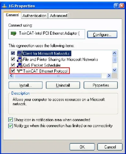
After the installation the driver appears activated in the Windows overview for the network interface (Windows Start -->System Properties -> Network)
Fig. 37: Windows properties of the network interface
Fig. 38: Incorrect driver settings for the Ethernet port
IP address of the port used
Note
IP address/DHCP
In most cases an Ethernet port that is configured as an EtherCAT device will not transport general IP packets. For this reason and in cases where an EL6601 or similar devices are used it is useful to specify a fixed IP address for this port via the “Internet Protocol TCP/IP” driver setting and to disable DHCP. In this way the delay associated with the DHCP client for the Ethernet port assigning itself a default IP address in the absence of a DHCP server
6.1.2
Notes regarding ESI device description
Installation of the latest ESI device description
The TwinCAT EtherCAT master/System Manager needs the device description files for the devices to be used in order to generate the configuration in online or offline mode. The device descriptions are contained in the so-called ESI files (EtherCAT Slave Information) in XML format. These files can be requested from the respective manufacturer and are made available for download. An *.xml file may contain several device descriptions.
The ESI files for Beckhoff EtherCAT devices are available on the Beckhoff website.
The ESI files should be stored in the TwinCAT installation directory (default TwinCAT2: C:\TwinCAT\IO \EtherCAT). The files are read (once) when a new System Manager window is opened, if they have changed since the last time the System Manager window was opened.
A TwinCAT installation includes the set of Beckhoff ESI files that was current at the time when the TwinCAT build was created.
For TwinCAT 2.11/TwinCAT 3 and higher, the ESI directory can be updated from the System Manager, if the programming PC is connected to the Internet (Option -> “Update EtherCAT Device Descriptions”)
Fig. 40: For TwinCAT 2.11 and higher, the System Manager can search for current Beckhoff ESI files auto-matically, if an online connection is available
Note
ESI
The *.xml files are associated with *.xsd files, which describe the structure of the ESI XML files. To update the ESI device descriptions, both file types should therefore be updated.
Device differentiation
EtherCAT devices/slaves are distinguished by 4 properties, which determine the full device identifier. The EL2521-0025-1018 ID consists of
• family key “EL” • name “2521” • type “0025”
• and revision “1018”
Fig. 41: Identifier structure
The order identifier consisting of name + type (here: EL2521-0010) describes the device function. The revision indicates the technical progress and is managed by Beckhoff. In principle, a device with a higher revision can replace a device with a lower revision, unless specified otherwise, e.g. in the documentation. Each revision has its own ESI description. See further notes [} 8].
Online description
If the EtherCAT configuration is created online through scanning of real devices (see section Online setup) and no ESI descriptions are available for a slave (specified by name and revision) that was found, the System Manager asks whether the description stored in the device should be used. In any case, the System Manager needs this information for setting up the cyclic and acyclic communication with the slave correctly.