Legal Notices...10
1 Welcome to SolidWorks 2013...13
Highlights ...13
Top Enhancements ...13
For More Information ...15
2 User Interface ...16
Customizing Shortcut Bars ...16
Easier Access to Troubleshooting and Administrative Tools ...16
FeatureManager Design Tree ...17
FeatureManager Design Tree Favorites ...17
FeatureManager Design Tree Views ...18
Subfolders in the FeatureManager Design Tree ...19
Scrolling Through CommandManager Tabs ...19
3 SolidWorks Fundamentals...20
Application Programming Interface ...20
Controlling the Save Reminder ...21
Documentation ...21
Help Navigation ...21
Motion Studies Tutorials ...21
SolidWorks Tutorials User Interface ...22
Equations ...22
Direct Input of Equations ...22
Enhanced Support for Units of Measurement ...25
Manipulating Views ...26
Orientation Dialog Box ...26
Updating Standard Views Without Using the Orientation Dialog Box ...29
View Rotation ...29
View Selector ...30
Measure Tool ...31
Measuring in Point to Point Mode ...32
Searching SolidWorks Options ...36
Selecting a SolidWorks Version When Opening a File ...36
SolidWorks Sounds ...36
Adding Sounds to Events in SolidWorks ...37
SolidWorks Startup ...37
Transferring Custom Properties When Inserting Configured Parts ...37
4 Administration...38
Converting Files to SolidWorks 2013 ...38
Interoperability Between SolidWorks 2012 SP5 and SolidWorks 2013 ...38
Save and Restore User Settings ...38
SolidWorks CAD Admin Dashboard ...39
The CAD Admin Dashboard Basic Workflow ...39
5 Installation...42
Push Install and Uninstall Method Using the Option Editor ...42
6 Assemblies...43
Assembly Visualization ...43
Additional Properties Available ...43
Colors for Group Identical ...44
Component Image Quality ...44
Excluding Hidden Components ...44
Import and Export of Settings ...44
Breaking All External References at Once ...45
Deleting Components from Subassemblies ...45
Derived Components ...45
Envelopes ...45
Creating an Envelope from a Component ...46
Creating an Envelope While Inserting a Component ...47
Changing Envelope Appearance ...48
Hiding and Showing Envelopes ...49
Changing Envelopes into Regular Components ...50
Other Changes for Envelopes ...51
Multiple Exploded Views per Configuration ...51
Adding Multiple Exploded Views ...51
Copying Exploded Views ...53
Inserting Components ...54
Improved Depth When Inserting Components ...54
Inserting Multiple Components ...54
Interference Detection ...57
Large Design Review ...60
Managing Configuration Data ...60
Skipping Rebuild After Editing Components ...61
SpeedPak Configurations ...61
Mass Properties in Assemblies ...61
Center of Mass Point in Assemblies ...61
Custom Inertia Properties in Assemblies ...62
Mates in Mirrored Subassemblies ...63
Replacing Components ...63
Selecting Subassemblies in the Graphics Area ...63
Snapshots ...63
Snapshots in Resolved Assemblies ...63
Snapshots in Walk-throughs ...63
Swept Cut Assembly Features ...64
7 CircuitWorks...65
Importing and Exporting ECAD File Features ...65
Exploring Layers, Traces, Filled Areas, and Vias ...65
8 Configurations...74
Design Tables ...74
Configuring Materials in a Design Table ...74
Data Validation in Design Tables ...75
Simplified Selection for Display States and Configurations ...75
Managing Configuration Data ...75
SpeedPak ...78
Disabling the SpeedPak Graphics Circle ...78
SpeedPak Creation from Parent Assembly ...79
SpeedPak PropertyManager ...82
Updating Subassembly SpeedPaks from Parent Assembly ...83
Transferring Custom Properties When Inserting Configured Parts ...83
9 SolidWorks Costing...84
Converting Simple Drilled Holes to Milled Pockets ...84
Multibody Parts ...84
Examining the Costing Templates for Multibody Parts ...85
Evaluating the Cost of a Multibody Part ...86
Evaluating the Cost of One Body in a Multibody Part ...87
Calculating the Cost of a Volume Feature ...92
10 Drawings and Detailing...93
Balloons ...93
Auto Balloon Functionality Works on Existing Balloons ...93
Auto Balloon Improvements ...97
Balloon Text Field Options ...97
Dimensions ...98
Add Dimensions to Baseline Dimensions ...98
Imported Tolerance and Precision Dimensions Parametric with Model ...99
Improved Arrows on Radius Dimensions ...100
Improved Control of Extension and Dimension Lines ...101
Insert Dimensions with Tolerances ...103
Radius and Diameter ISO Leader Dimensions ...104
Radius, Diameter, Chamfer, and Hole Callout Bent Leader Improvements ...105
Reference Center of Mass in Drawings ...106
Drawing Views ...107
Convert Drawing View to Sketch ...107
Multiple Exploded Views ...109
New Edge Types for Flat Pattern Views ...109
New Section Tool User Interface ...110
Save Drawing View as DXF or DWG File ...124
SpeedPak Drawing Support ...124
Layers ...124
Center Marks and Centerlines Assigned to Layers ...124
Improved Access to Layer Function ...125
Other Annotations ...126
Display Note Behind Sheet ...126
Dowel Pin Symbol Support ...127
GTOL Allows Notation Below the Feature Control Frame ...127
JIS Weld Symbol Improvements ...128
Linking Cut List Properties to Annotations ...129
Padding Annotation Option ...131
Revision Cloud ...132
Sheet Metal Bend Note Improvements ...135
SolidWorks eDrawings Markups Visible in SolidWorks ...135
Use Mouse Wheel to Zoom While Editing Text Field ...135
View Label Custom Names ...136
Tables ...136
Improved Cell Padding in SolidWorks Tables ...136
eDrawings and eDrawings Pro for iPad ...138
Exploded Views ...139
Saving and Sending Files in eDrawings 64-bit Installations ...139
Stereographic Viewing ...139
Version Support for Mac and PowerPC ...139
12 SolidWorks Enterprise PDM...140
Administration Tool ...140
Delayed in State Notifications ...140
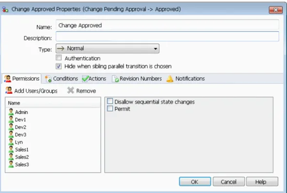
Parallel Workflow Transitions ...141
Recently Used List ...145
Workflow Editor Update ...145
File Explorer and SolidWorks Add-in ...148
Bill of Materials Tab Improvements ...148
Close SolidWorks Files on Check In ...149
Contains and Where Used Tab Improvements ...149
Full Row Selection Highlighting in Windows Explorer ...150
Notification Editor Update ...150
Quantity Specification for Manually Created File References ...153
User Information Pop-up ...153
Version Free Variables ...155
Windows Explorer Favorites Links ...156
13 SolidWorks Flow Simulation...158
Compare Configuration Mode ...158
Erosion Plot ...159
Evenly Spaced Surface Streamline Algorithm ...159
Improved Feature Tree ...160
Improved Geometry Handling ...160
Low Temperature Condensation ...161
Parametric Study Mode ...162
Improved eDrawings Plots ...162
14 Import/Export...163
Import Performance Enhancements ...163
15 Model Display...164
Appearances ...164
Scaling Textural Appearances, Surface Finishes, and Decals ...166
PhotoView 360 ...168
Final Render Window ...168
PhotoView 360 Options ...169
Using Modo Appearances in SolidWorks ...169
16 Motion Studies...170
Motion Studies Tutorials ...170
17 Parts and Features...171
Edge Selection Toolbar Available for Fillets ...172
Enhanced Support for Mounting Bosses ...172
Creating the Mounting Boss ...173
Enhanced Support for Thin Extrudes ...176
Selecting Multiple Contours for Thin Extrudes ...176
Enhancement for Inserting Cosmetic Threads ...178
Enhancements to Part Reviewer ...178
Highlighting Related Bodies or Surfaces in Multibody Parts ...178
Inserting Dowel Holes with the Hole Wizard ...178
Linking a Defeature Model to Original ...179
Mass Properties in Parts ...179
Custom Inertia Properties in Parts ...179
Mass Properties Dialog Box ...179
Point at the Center of Mass ...179
Modifying Geometry with the Intersect Tool ...180
Creating Geometry from Solids, Surfaces, or Planes ...181
Multibody Library Features ...185
Selecting End Conditions for Extruded Features ...185
Show Hidden Bodies ...186
Smarter Configuration Switching ...186
Transferring Custom Properties ...186
Varying Dimension Patterns ...186
Varying the Spacing and Dimensions of All Instances ...186
Modifying Dimensions of One Instance ...187
Restoring Instances to Their Original State ...188
Weldments ...188
Bounding Boxes ...188
Creating Bounding Boxes ...190
18 SolidWorks Plastics...191
Auto Route Tool Supports Routing Along Existing Geometry ...192
Creating Drawings for Flexible Tubing Routes ...192
Enhanced Pipe Penetration ...193
Enhanced Support for Exporting Pipe and Tube Data ...193
Improvements for Flattened Routes ...193
Improvements for Ribbon Cable Routes ...193
Adding Slopes for Pipe Routes ...194
Adding a Slope ...195
Support for Tubing in P&ID Files ...195
Validation Check for Routing Component Wizard ...195
20 Sheet Metal...196
Bend Notes ...196
Forming Tools ...197
Multibody Parts ...198
21 SolidWorks Simulation...200
Beams ...200
Contact ...201
Automatic Contact Set Detection ...201
Detecting Interfering Faces ...202
Shell Edges to Beam Bonding ...202
Incremental Meshing ...203
Interface ...203
Error Messages ...204
Materials in Design Studies ...204
Design Evaluation of a Knob based on Material ...205
Results ...207
Factor of Safety for Selected Bodies ...207
Plots on Selected Entities ...208
Shell Results ...209
Storing Results ...209
Sensors ...210
Defining a Transient Sensor ...210
Submodeling ...210
Submodeling Principles ...211
Submodeling Study for a Pressure Vessel ...211
Environmental Impact of Painted Parts ...221
Exporting Settings for a SolidWorks Sustainability Study ...222
Financial Impact of Material Choices ...222
Viewing Financial Impact ...223
Using Find Similar to Reduce Costs ...224
Assigning Financial Impact to a Custom Material ...224
Improved Calculation Consistency ...225
TRACI Impact Assessment Methodology ...225
Units in the TRACI Methodology ...226
Using TRACI to Assess Sustainability ...227
Selecting Units in the Find Similar Dialog Box ...228
24 SolidWorks Workgroup PDM...229
Limiting Export to Files in the Current Revision Scheme ...229
©1995-2013, Dassault Systèmes SolidWorks Corporation, a Dassault Systèmes S.A. company,
175 Wyman Street, Waltham, Mass. 02451 USA. All Rights Reserved.
The information and the software discussed in this document are subject to change without notice and are not commitments by Dassault Systèmes SolidWorks Corporation (DS SolidWorks). No material may be reproduced or transmitted in any form or by any means, electronically or manually, for any purpose without the express written permission of DS SolidWorks.
The software discussed in this document is furnished under a license and may be used or copied only in accordance with the terms of the license. All warranties given by DS SolidWorks as to the software and documentation are set forth in the license agreement, and nothing stated in, or implied by, this document or its contents shall be considered or deemed a modification or amendment of any terms, including warranties, in the license agreement.
Patent Notices
SolidWorks®3D mechanical CAD software is protected by U.S. Patents 5,815,154; 6,219,049; 6,219,055; 6,611,725; 6,844,877; 6,898,560; 6,906,712; 7,079,990; 7,477,262; 7,558,705; 7,571,079; 7,590,497; 7,643,027; 7,672,822; 7,688,318; 7,694,238; 7,853,940; 8,305,376; and foreign patents, (e.g., EP 1,116,190 B1 and JP 3,517,643).
eDrawings®software is protected by U.S. Patent 7,184,044; U.S. Patent 7,502,027; and Canadian Patent 2,318,706.
U.S. and foreign patents pending.
Trademarks and Product Names for SolidWorks Products and Services
SolidWorks, 3D PartStream.NET, 3D ContentCentral, eDrawings, and the eDrawings logo are registered trademarks and FeatureManager is a jointly owned registered trademark of DS SolidWorks.
CircuitWorks, FloXpress, PhotoWorks, TolAnalyst, and XchangeWorks are trademarks of DS SolidWorks.
FeatureWorks is a registered trademark of Geometric Ltd.
SolidWorks 2013, SolidWorks Enterprise PDM, SolidWorks Workgroup PDM, SolidWorks Simulation, SolidWorks Flow Simulation, eDrawings, eDrawings Professional, and SolidWorks Sustainability are product names of DS SolidWorks.
Other brand or product names are trademarks or registered trademarks of their respective holders.
COMMERCIAL COMPUTER SOFTWARE - PROPRIETARY
The Software is a “commercial item” as that term is defined at 48 C.F.R. 2.101 (OCT 1995), consisting of “commercial computer software” and “commercial software documentation” as such terms are used in 48 C.F.R. 12.212 (SEPT 1995) and is provided to the U.S. Government
Software with rights beyond those set forth above, you will notify DS SolidWorks of the scope of the request and DS SolidWorks will have five (5) business days to, in its sole discretion, accept or reject such request. Contractor/Manufacturer: Dassault Systèmes SolidWorks Corporation, 175 Wyman Street, Waltham, Massachusetts 02451 USA.
Copyright Notices for SolidWorks Standard, Premium, Professional, and Education Products
Portions of this software©1986-2012 Siemens Product Lifecycle Management Software Inc. All rights reserved.
This work contains the following software owned by Siemens Industry Software Limited: D-Cubed™ 2D DCM©2012. Siemens Industry Software Limited. All Rights Reserved.
D-Cubed™ 3D DCM©2012. Siemens Industry Software Limited. All Rights Reserved.
D-Cubed™ PGM© 2012. Siemens Industry Software Limited. All Rights Reserved.
D-Cubed™ CDM©2012. Siemens Industry Software Limited. All Rights Reserved.
D-Cubed™ AEM© 2012. Siemens Industry Software Limited. All Rights Reserved.
Portions of this software©1998-2012 Geometric Ltd.
Portions of this software©1996-2012 Microsoft Corporation. All rights reserved. Portions of this software incorporate PhysX™by NVIDIA 2006-2010.
Portions of this software©2001-2012 Luxology, LLC. All rights reserved, patents pending. Portions of this software©2007-2011 DriveWorks Ltd.
Copyright 1984-2010 Adobe Systems Inc. and its licensors. All rights reserved. Protected by U.S. Patents 5,929,866; 5,943,063; 6,289,364; 6,563,502; 6,639,593; 6,754,382; Patents Pending.
Adobe, the Adobe logo, Acrobat, the Adobe PDF logo, Distiller and Reader are registered trademarks or trademarks of Adobe Systems Inc. in the U.S. and other countries.
For more DS SolidWorks copyright information, see Help > About SolidWorks.
Copyright Notices for SolidWorks Simulation Products
Portions of this software©2008 Solversoft Corporation.
PCGLSS©1992-2010 Computational Applications and System Integration, Inc. All rights reserved.
Copyright Notices for SolidWorks Enterprise PDM Product
Outside In® Viewer Technology,©1992-2012 Oracle
©2011, Microsoft Corporation. All rights reserved.
Copyright Notices for eDrawings Products
Portions of this software©1995-2010 Spatial Corporation.
The eDrawings® for Windows® software is based in part on the work of the Independent JPEG Group.
Portions of eDrawings®for iPad®copyright ©1996-1999 Silicon Graphics Systems, Inc. Portions of eDrawings®for iPad®copyright ©2003 – 2005 Apple Computer Inc.
Welcome to SolidWorks 2013
This chapter includes the following topics: • Highlights
• Top Enhancements
• For More Information
Highlights
SolidWorks®2013 includes many enhancements and improvements, most in direct
response to customer requests. This release focuses on the following themes:
Image courtesy of Fender®Musical Instruments
Corporation • More powerful design
capabilities: You can model and verify complex geometries faster and with more control. New tools help you create cost effective designs that meet your objectives.
• More effective collaboration: There is an expanded range of collaboration for design and product development with new tools for release interoperability, manufacturing cost estimation, and technical communication.
• Increased performance and productivity: Take advantage of processing power to create and simulate models and monitor SolidWorks functionality and performance.
Top Enhancements
The top enhancements for SolidWorks 2013 provide improvements to existing products and innovative new functionality.
Orientation Dialog Box on page 26
View Selector on page 30
SolidWorks CAD Admin Dashboard on page 39 Administration
Previous Release Interoperability on page 34 Installation
Envelopes on page 45 Assemblies
Multiple Exploded Views per Configuration Inserting Multiple Components on page 54
Importing and Exporting ECAD File Features on page 65
CircuitWorks
Disabling the SpeedPak Graphics Circle on page 78 Configurations
Speedpak Creation from Parent Assembly Turned Parts
SolidWorks Costing
Convert Drawing View to Sketch Drawings and Detailing
Imported Tolerance and Precision Dimensions Parametric with Model
Revision Cloud
New Section Tool User Interface
Delayed in State Notifications on page 140 SolidWorks Enterprise
PDM
Notification Editor Update on page 150
Parallel Workflow Transitions on page 141
User Information Pop-up on page 153
Version Free Variables on page 155
Workflow Editor Update on page 145
3D Bounding Boxes Parts and Features
Enhanced Support for Mounting Bosses Enhanced Support for Thin Extrudes
Modifying Geometry With the Intersect Tool Varying Dimension Patterns on page 186
Improvements for Ribbon Cable Routes Incremental Meshingon page 203
Simulation
Submodeling on page 210
Conic Curves on page 215 Sketching
TRACI Impact Assessment Methodology on page 225 Sustainability
All features are available in SolidWorks Standard, SolidWorks Professional, and SolidWorks Premium unless otherwise noted.
For More Information
Use the following resources to learn about SolidWorks:
This guide is available in PDF and HTML formats. Click: • Help > What's New > PDF
• Help > What's New > HTML What's New in PDF
and HTML
In SolidWorks, click the symbol to display the section of this manual that describes an enhancement. The symbol appears next to new menu items and the titles of new and changed PropertyManagers.
To enable Interactive What's New, click Help > What's New > Interactive.
Interactive What's New
What's New Examples are updated at every major release to provide examples of how to use most top enhancements in the release.
To open What's New Examples click Help > What's New > What's New Examples.
What's New Examples
Contains complete coverage of our products, including details about the user interface, samples, and examples.
Online Help
Provides information about late changes to our products. Release Notes
User Interface
This chapter includes the following topics: • Customizing Shortcut Bars
• Easier Access to Troubleshooting and Administrative Tools
• FeatureManager Design Tree
• Scrolling Through CommandManager Tabs
Customizing Shortcut Bars
The ability to customize shortcut bars has been improved.
Shortcut bars appear when you press the S key in an open part, assembly, drawing, or sketch.
To customize a shortcut bar:
1. Click Tools > Customize or right-click the shortcut bar and click Customize. 2. In the Customize dialog box, on the Shortcut Bars tab, click one of the following:
• Part • Assembly • Drawing • Sketch
The shortcut bar appears.
3. For Toolbar, select a command group and drag the desired buttons onto the shortcut bar.
To remove buttons from the shortcut bars, drag the button onto the graphics area until a red X appears.
Easier Access to Troubleshooting and Administrative Tools
Builder, a utility that you can use to create a customized interface for entering properties into SolidWorks files. The tabs you create appear in the Custom Properties tab of the Task Pane.
Analyzes your system, suggests possible solutions, and captures data that can help technical support personnel diagnose problems.
SolidWorks Rx
Analyzes your system performance, compares it to other users, and allows you to share your score.
Performance Benchmark Test
Reports the results of your SolidWorks Performance Test in comparison to other users. This tool is available only for subscription customers. Compare My Score
The Copy Settings Wizard saves, restores, and
propagates system settings to users, computers, or profiles. You can also run the Copy Settings Wizard from the Tools menu. SeeSave and Restore User Settings
on page 38. Copy Settings Wizard
FeatureManager Design Tree
FeatureManager Design Tree Favorites
You can add commonly used features, sketches, and reference geometry to the Favorites folder in the FeatureManager®design tree.
With the Favorites folder, you can easily access items in a part or assembly with a very long feature tree. You can also use the Favorites folder to highlight features for other team members to look at during collaboration.
FeatureManager.
To remove a feature from the Favorites folder, right-click the feature and click Remove from Favorites.
If you right-click an item in the Favorites folder and click Delete, the item is permanently deleted from the part or assembly.
Any changes you make to an item in the Favorites folder are also made wherever the item appears in the tree. For example, if you rename an item in Favorites, all other instances of that item in the FeatureManager design tree appear with the new name.
FeatureManager Design Tree Views
In part documents, you can set the FeatureManager design tree to show features in the order they were created, instead of hierarchically.
Right-click in the FeatureManager design tree and click Tree Display > Show Flat Tree View. In Flat Tree View, curves, 2D sketches, and 3D sketches are not absorbed into the features that reference them. Instead, they are shown in the order of creation.
Flat Tree View is only available for parts.
All regular FeatureManager design tree functionality is available in Flat Tree View, with the exception of user-created folders. You can reorder features in Flat Tree View, changing design intent.
Not all items are unabsorbed in Flat Tree View. The following features continue to absorb items in Flat Tree View:
• Simple hole • Hole Wizard hole • Mounting boss • Lip/Groove
• Snap hook groove • Vent
• Snap hook
• Sheet metal feature • Library feature
• Weldment structural member • Sketch block
Flat Tree View: Items are shown in the order of creation, with the exception of the Hole Wizard holes, which still absorb the sketches.
Normal View: Items are displayed
hierarchically, with sketches absorbed into features.
Subfolders in the FeatureManager Design Tree
In parts and assemblies, you can create subfolders in the FeatureManager design tree. You can use multiple layers of folders to organize long FeatureManager design trees. To create a subfolder, select one or more items within a folder, right-click, and click Add to New Folder. You can drag additional items into the subfolder from any level in the tree.
As in previous releases, the software prevents actions that violate parent-child relationships.
To expand or collapse a folder and all its subfolders, right-click and click Expand All or Collapse All. To retain a subfolder's expanded or collapsed state when you expand or collapse its parent folder, right-click the parent folder and click Expand Item or Collapse Item.
Any command that can be applied to folders can be applied to subfolders. When you apply a command to a folder, it is applied to that folder’s subfolders as well. For example, when you suppress a folder, all items in the folder are suppressed, including its subfolders and the items they contain.
Scrolling Through CommandManager Tabs
Use Ctrl+Page Up and Ctrl+Page Down to scroll through the CommandManager tabs. As in previous releases, you can change the shortcut keys by clicking Tools > Customize and clicking the Keyboard tab.
SolidWorks Fundamentals
This chapter includes the following topics: • Application Programming Interface
• Controlling the Save Reminder
• Documentation
• Equations
• Manipulating Views
• Measure Tool
• Opening Files - Quick Filter Buttons
• Previous Release Interoperability
• Searching SolidWorks Options
• Selecting a SolidWorks Version When Opening a File
• SolidWorks Sounds
• SolidWorks Startup
• Transferring Custom Properties When Inserting Configured Parts
Application Programming Interface
SolidWorks 2013 includes the following functionality:
• Microsoft®Visual Basic®for Applications (VBA) programming language, one of the
programming languages available to record, edit, and run macros in SolidWorks, has been upgraded to support both 32-bit and 64-bit data types.
• SolidWorks primary interop assemblies created with Microsoft .NET Framework: • Version 2.0 are in install_dir\api\redist\CLR2. This is the version of primary interop
assemblies to use with SolidWorks VSTA (VB.NET and C#) macros. • Version 4.0 are in install_dir\api\redist.
• Both SolidWorks Costing and SolidWorks Sustainability include APIs. Other major enhancements include the ability to:
• Insert cosmetic weld beads and access their feature data and folders. • Get the direction vectors of connection points.
• Get or set whether to display a ruler when the drag arrow manipulator moves.
• Get or set whether to allow the unidirectional drag arrow manipulator to change direction when dragged past length = 0.
• Create a forming tool feature with a point of insertion. • Add display dimensions to a macro feature.
• Get or set the background processing option and handle background processing events for drawings.
• Handle drawing sheet activation events. • Hide Undo operations.
• Specify the type of numbering and whether to show the detailed cut list in indented BOM tables.
• Get or set the state of the flyout FeatureManager design tree. • Make a component virtual by saving it in an assembly.
• Vary individual instances of linear and circular feature patterns. • Get the unique name of a section view.
• Get or set the transparency level of unmodified components in assemblies opened in Large Design Review mode.
• Create a SpeedPak configuration that includes all faces and a specified threshold of parts or bodies for the active configuration.
• Copy appearances to the clipboard and apply them to faces, features, bodies, components, and parts.
• Merge bend tags in drawings of sheet metal parts.
• Get or set the text format of bend notes in the drawing views of sheet metal parts. • Place the selected note, located on the sheet format, behind the drawing sheet. • Insert a note that contains all of the cut list item properties of a sheet metal part. See SolidWorks 2013 API Help Release Notes for late-breaking updates.
Controlling the Save Reminder
You can control how long the save notification is displayed.
Click Tools > Options > System Options > Backup/Recover and under Save notification, enter a value for Automatically dismiss after n seconds.
Documentation
Help Navigation
Help content has more consistent presentation and styling.
Links to Related Topics are now more accessible. They appear on the right side of the page and remain in place and visible as you scroll the Help content.
Motion Studies Tutorials
There are two new Motion Studies tutorials: Motion Analysis Redundancies and Motion Along a Path.
To access a tutorial:
1. Click Help > SolidWorks Tutorials.
The access page for SolidWorks tutorials has been redesigned for improved user experience.
The layout and groupings of tutorials have been reorganized. All tutorials, including SolidWorks Simulation tutorials, are available from one interface. Links for navigating through the tutorials are always visible at the bottom of the page.
To open SolidWorks tutorials, click Help > SolidWorks Tutorials.
Equations
Direct Input of Equations
For many features, you can enter and modify equations directly in PropertyManager fields that allow numerical inputs. You can create equations with global variables, functions, and file properties without accessing the Equations, Global Variables and Dimensions dialog box.
The following table lists where this capability is available:
Assembly Features Part Features
Extruded Cut Extruded Boss/Base
Revolved Cut Extruded Cut
Chamfer Revolved Boss/Base Hole Revolved Cut Linear Pattern Fillet Circular Pattern Chamfer Scale Shell Rib Draft Base Flange Edge Flange Linear Pattern Circular Pattern Curve Driven Pattern Extruded Surface Revolved Surface Fillet Surface
For example, in the PropertyManager for the Extruded Boss/Base feature, you can enter equations in:
• Depth fields for Direction 1 and Direction 2 • Draft fields for Direction 1 and Direction 2
• Thickness fields for a Thin Feature with two direction types • Offset Distance field
To create an equation in a numeric input field, start by entering = (equal sign). A drop-down list displays options for global variables, functions, and file properties. Numeric input fields that contain equations can display either the equation itself or its evaluated value. You can toggle between the equation and the value by clicking the Equations or Global Variable button that appears at the beginning of the field.
You cannot change an evaluated value when it is displayed in the input field, but you can toggle to the equation and then edit or delete the equation.
Increment Values with Spin Arrows
You can quickly increment or decrement values in equations using the spin arrows that appear at the end of a numeric input field.
For example, use the following keys or key combinations:
• Click the Up or Down arrow to change the value by 10. For example, if the value is 10.00mm, click the Up arrow to increase it to 20.00mm.
• Press Alt+Up or Alt+Down arrow to change the value by 1. If the value is 10.00mm, Alt+Up increases the value to 11.00mm.
• Press Ctrl+Up or Ctrl+Down arrow to change the value by a 100. If the value is 10.00mm, Ctrl + Up increases the value to 110.00mm
The units of the Spin Box Increments may vary depending on the settings specified in System Options.
Using Equations in the Chamfer PropertyManager
You can bevel the edges of a model using equations.
1. Openinstall_dir\samples\whatsnew\fundamentals\simple_frontplate.sldprt. 2. In the FeatureManager design tree, right-click the Equations folder, and select
Manage Equations.
The Equations dialog box lists two global variables and three equations. 3. Click OK to close the Equations dialog box.
4. Click Chamfer (Features toolbar), or Insert > Features > Chamfer. 5. In the PropertyManager, under Chamfer Parameters, do the following:
a) In the graphics area, select the four edges of the front face for Edges and Faces or Vertex .
b) Create a new global variable in Distance by typing =chamferand click in
d) Type =in Angle . Select Functions > sin() from the flyout menu. Then type
sin(90)*10and click in the input field.
The field displays an Equations button . Click to toggle the display between the equation and the value.
6. Click .
The global variable "chamfer" and the angle equation are listed in the Equations dialog box.
To remove either a global variable or equation from the PropertyManager, click in the input field and press Delete.
Enhanced Support for Units of Measurement
You can specify the units of measurement for global variables, and for the values and equations that define the global variables. You can define the units in the Equations and Modify dialog boxes for dimensions, and in PropertyManagers that support equations. Assigning units of measure in equations ensures that you do not need to edit the equations if you change the unit of measure property of a document. It also allows you to create equations that mix values with different units of measurement.
For example, you can create a global variableLengthand define it by the equation:
=100in + 3mm + 5cm. The equation includes values with three different units of measurement. If the unit of measurement of the document is inches, thenLength
evaluates to 102.087in. If you change the unit of measurement of the document to millimeters, thenLengthautomatically evaluates to the value of 2593mm. You do not need to edit the equation, or be concerned that the size of the part will change.
In the Equation and Modify dialog boxes, type-ahead lists help you assign a valid unit of measurement to each value in an equation.
Orientation Dialog Box
You can create custom views and save them to SolidWorks, allowing you to reuse saved views in different documents.
You also access snapshots in the custom view list. The Orientation dialog box now shares the same set of buttons for standard views as the Heads-up View toolbar.
The Orientation dialog box also provides access to the View Selector .
Axonometric Views are displayed in a drop-down list. Click to select isometric, trimetric, or dimetric.
To activate the Orientation dialog box, press the spacebar or click View Orientation (Heads-up View toolbar) and click More Options .
Using the Orientation Dialog Box and the View Selector
In this example, you use the Orientation dialog box and the View Selector to manipulate views, update standard views, and save a custom view to SolidWorks.
First, you use the Orientation dialog box and the View Selector:
1. Openinstall_dir\samples\whatsnew\fundamentals\RobotArm.sldprt. 2. Press the spacebar or click View > Modify > Orientation.
The Orientation dialog box appears.
3. Click View Selector .
The View Selector is activated. As you hover over the buttons in the Orientation dialog box, the corresponding faces dynamically highlight in the View Selector.
4. Select the back view in the View Selector or click Back in the Orientation dialog box.
5. Press Ctrl + spacebar to activate the View Selector. Select one of the diagonal views.
Updating Standard Views
You can use the Orientation dialog box to update standard views. 1. Press the spacebar. Click to deactivate the View Selector.
When the View Selector is active, it automatically launches when you open the Orientation dialog box.
2. Click to pin the Orientation dialog box.
3. Click Top .
The model rotates to the top view.
4. Click Update Standard Views .
The software prompts you to select the standard view you want to assign the current view to.
The standard views update, with the current view set as the front view.
Saving a Custom View to SolidWorks
You can create a custom view and save it so it is accessible other documents. 1. Rotate the model as shown.
2. Click New View .
3. In the dialog box, name the viewForeshortened and click OK.
Your view appears in the Orientation dialog box. You can now toggle between any of the standard views and the custom view you created.
4. Mouse over Foreshortened in the Orientation dialog box. Options to save or delete the view appear. Click Save to SolidWorks.
The image appears next to Foreshortened, indicating that it is available in other SolidWorks documents.
5. Open the document install_dir\samples\whatsnew\fundamentals\
RobotLeg.sldprt
6. In the Orientation dialog box, click Saved Views and click Foreshortened.
Foreshortened is added to the Orientation dialog box and the model rotates to the saved view.
Dialog Box
You can update standard views without opening the Orientation dialog box. To update standard views:
1. Right-click in the graphics area and click Set Current View As. Select the desired view from the menu.
2. Click Yes in the warning dialog box.
The scene floor automatically updates to be aligned with the bottom view plane, updating floor reflections and shadows.
By default, the scene floor is aligned with the bottom view plane. To align the scene floor differently, right-click the scene in the DisplayManager and click Edit Scene. Under Floor, make a selection in Align floor with.
View Rotation
You can lock the vertical axis in relation to the front view during view rotation. This prevents the model from tipping and tilting about the horizon plane and creates the impression that the model is on a floor.
Right-click in the graphics area and click Rotate about scene floor.
The vertical axis locks in relationship to the front view. If your model's front view does not match the vertical axis you want to rotate around, you can change the front view. SeeUpdating Standard Views Without Using the Orientation Dialog Boxon page 29.
For example, this image shows the front view of the toy tractor.
The vertical axis of rotation locks around the Y axis and the floor is parallel to the X axis. In the following image, the dotted red arrow indicates the locked axis of rotation:
The Y axis is the vertical axis by default. However, if you update standard views, the vertical axis might change
View Selector
You can use the View Selector to see and select model views in context.
Press Ctrl + Spacebar or click View Selector in the Orientation dialog box.
The View Selector helps you see what right, left, front, back, top, and isometric views of your model will look like when selected.
The View Selector also allows you to select additional standard and isometric views. For example, in the image below, the bottom isometric view is highlighted.
For a What's New Example that uses the View Selector, seeUsing the Orientation Dialog Box and the View Selectoron page 26.
Measure Tool
Improvements have been made to the Measure Tool functionality and user interface.
Point-to-Point Mode
You can measure the distance between two points on your model. This mode supports snapping to model faces and edges, as well as midpoints, quadrant points, and
intersections.
Arc/Circle Measurements
You can create measurements with custom arc conditions. For example, you can measure the distance from the center of one arc or circle to the outer edge of another. Use drop-down menus on the Measure callouts in the graphics area to toggle between center, maximum, minimum, and custom distances.
Last Used Settings
The Measure tool retains settings from the last time it was used.
History
Click History to see measurements made during the current session of SolidWorks.
User Interface
The icon has been replaced with to indicate the option to create a sensor from the current measurement.
You can use Point-to-Point mode to compare the distance between two faces at different places on the model.
1. Openinstall_dir\samples\whatsnew\fundamentals\clip.sldprt.
2. Click Measure (Tools toolbar) or Tools > Measure. 3. In the Measure dialog box, click Point-to-Point .
4. Select a point near the center of one of the flat faces of the grip, and then a point near the center of the other flat face, rotating the model if necessary.
The measurement appears in the graphics area and in the Measure dialog box.
5. Click in the graphics area to clear the current measurement.
6. Select the midpoint of the top edge of the flat face of the grip, and then the midpoint of the opposite edge.
When you hover over an edge, the midpoint appears, allowing you to select it, like in a sketch.
7. Click in the graphics area to clear the current measurement. 8. Click Point-to-Point to exit Point-to-Point mode.
Measuring the Distance Between Two Circles
You can measure the distance between two circles using Maximum, Minimum, and Custom Distances.
1. With the Measure dialog box still open, rotate the model so you can see the bottom face.
2. Click the edges of the two holes.
The measurement appears in the graphics area and in the Measure dialog box.
3. Click the down arrow on the measure callout in the graphics area to toggle between Center, Maximum, and Minimum Distance.
4. To set a custom arc condition, click Arc/Circle in the Measure tool and click Custom Distance . Set the following values:
a) Under First Arc Condition, select Minimum Distance. b) Under Second Arc Condition, select Center Distance.
5. Click Measurement History to view all the measurements made during this
session of SolidWorks. 6. Close the Measure tool.
Quick Filter buttons in the Open dialog box allow quicker access to commonly-used SolidWorks file types.
Click Quick Filter buttons in any combination to see the desired file type. For example, click Filter Parts to see only parts. To see parts and assemblies, click Filter Parts
and then Filter Assemblies .
Opening Top-Level Assemblies
If you have a folder containing assemblies and subassemblies, you can use a quick filter button to see only top-level assemblies.
Click Filter Top-Level Assemblies to see only top-level assemblies. If you have a very large number of files in the folder, this may take a while.
Previous Release Interoperability
You can open SolidWorks 2013 parts and assemblies using SolidWorks 2012 Service Pack 5.
From SolidWorks 2012 on, you can open a future version file in Service Pack 5 of the previous release. For example, in SolidWorks 2013 Service Pack 5 you will be able to open SolidWorks 2014 files. Interoperability is only supported between consecutive releases. For example, you cannot open a SolidWorks 2014 file in SolidWorks 2012 Service Pack 5.
Future version files appear in read-only mode when opened in the previous release. However, once you upgrade to the next version of SolidWorks, all the FeatureManager design tree data is available.
SolidWorks 2013 files have reduced functionality in SolidWorks 2012 Service Pack 5. SolidWorks 2013 files will not have most FeatureManager design tree data when opened in SolidWorks 2012 Service Pack 5. Any actions that require FeatureManager design tree data cannot be performed with a SolidWorks 2013 document open in SolidWorks 2012 Service Pack 5.
The following table summarizes what you can and cannot do in SolidWorks 2012 Service Pack 5:
You can create drawings of SolidWorks 2013 parts and assemblies in SolidWorks 2012 with some limitations. You cannot:
• Insert model items. • Access FeatureManager
design tree data such as weldment cut lists and weld beads.
You cannot open 2013 drawings in SolidWorks 2012 Service Pack 5 You can work with
SolidWorks 2013 parts and subassemblies in a
SolidWorks 2012 assembly. In a SolidWorks 2012 assembly, you can:
• Mate the SolidWorks 2013 component or
subassembly to SolidWorks 2012 or SolidWorks 2013 components.
• Add a Bill of Materials that includes SolidWorks 2012 and SolidWorks 2013 components.
• Suppress and unsuppress SolidWorks 2013
components.
• Create a drawing of the SolidWorks 2012 assembly that includes both
SolidWorks 2012 and SolidWorks 2013 components.
• Use interference detection when mating SolidWorks 2013 and SolidWorks 2012 parts.
• Mirror and pattern components from SolidWorks 2013.
• See and reference default planes and origins of the SolidWorks 2013 part or subassembly.
You cannot edit mates or components in the SolidWorks 2013 subassembly. With a SolidWorks 2013 part
or assembly open in SolidWorks 2012 you can: • View configurations. • Use the Measure tool. • View Mass Properties and
Custom Properties. • View Materials
You cannot edit SolidWorks 2013 parts or assemblies in SolidWorks 2012.
In SolidWorks 2013, you must rebuild and save data for each configuration that you want to be available in SolidWorks 2012 Service Pack 5. SeeManaging Configuration Data on page 75.
You can search for options and settings within Tools > Options.
In the Options dialog box, enter a term in the Search box and select a result. You can search for both System and Document Options.
As you type in the Search string, search results dynamically appear. Click a search result to be taken to the appropriate Options page. Search results are highlighted in the Options dialog box, unless they appear in a drop-down menu.
Your search may not be visible on the Options page due to the type of model you have open or the current settings.
Selecting a SolidWorks Version When Opening a File
If you use Windows®Explorer to open a SolidWorks file, and you have multiple versions
of SolidWorks installed on your computer, a dialog box prompts you to select which version to use to open the file.
The Multiple Versions dialog box displays up to the three most recent versions of
SolidWorks that are installed on your computer. For example, if SolidWorks versions 2009 to 2013 are installed, you can choose to open the file with version 2011, 2012 or 2013. If you want to use the selected version to open all of your SolidWorks files, you can suppress the dialog box by selecting Do not show this again.
You can reset files with the version of SolidWorks that last saved them from Tools > System Options > File Explorer and clicking Restore file Associations. For example, you might use this if you had SolidWorks 2012 SPO4 and the SolidWorks 2013 beta on your machine, and then uninstalled the SolidWorks 2013 beta.
To restore file associations, you must launch SolidWorks with Run as administrator privileges. These steps may vary per operating system. For information on how to Run as administrator, consult the Microsoft Knowledge Base.
SolidWorks Sounds
You can add sounds to SolidWorks program events using the Windows Sounds dialog box. You can add sounds to the following SolidWorks events:
• Animation Complete • Collision Detected
• Design Study Scenario Complete • Interference Detected
• Mesh Completed Successfully • Mesh Failure
• Open File Complete • Rebuild Complete • Rebuild Error • Render Complete
To assign sounds to events in SolidWorks:
1. Click Tools > Options > System Options > General and select Enable sounds for SolidWorks events.
2. Click Configure Sounds.
The Windows Sound dialog box opens.
3. Scroll to the bottom of the Program Events box. Under SolidWorks select the event you want to add a sound to.
4. Select a sound from the Sounds drop-down list. 5. Click OK.
SolidWorks Startup
You can cancel the startup of SolidWorks if you launch it accidentally.Messages on the splash screen inform you of the startup progress.
SolidWorks Fast Start
To launch more quickly, SolidWorks begins loading components in the background when you start your computer.
To turn off SolidWorks Fast Start, from Windows click Start > Startup. Right-click SolidWorks Fast Start and click Delete.
See SolidWorks Help:SolidWorks Fast Start.
Transferring Custom Properties When Inserting Configured
Parts
Improvements have been made to transferring of custom properties when you insert a configured part into another part.
Administration
This chapter includes the following topics: • Converting Files to SolidWorks 2013
• Interoperability Between SolidWorks 2012 SP5 and SolidWorks 2013
• Save and Restore User Settings
• SolidWorks CAD Admin Dashboard
Converting Files to SolidWorks 2013
Opening a SolidWorks document from an earlier release might take extra time. After you open and save a file, subsequent opening time returns to normal.
You can use SolidWorks Task Scheduler to convert multiple files from an earlier version to the SolidWorks 2013 format. Click Windows Start, then All Programs > SolidWorks 2013 > SolidWorks Tools > SolidWorks Task Scheduler.
In the Task Scheduler:
• Click Convert Files and specify the files or folders to convert.
• For files in a SolidWorks Workgroup PDM vault, use Convert Workgroup PDM Files. For files in a SolidWorks Enterprise PDM vault, use the utility provided with Enterprise PDM.
After you convert files to SolidWorks 2013, you cannot open them in older SolidWorks versions, with the exception of SolidWorks 2012 Service Pack 5. SeePrevious Release Interoperability on page 34 for more information.
Interoperability Between SolidWorks 2012 SP5 and
SolidWorks 2013
If you have SolidWorks 2012 Service Pack 5, you can open parts and assemblies created with SolidWorks 2013.
However, the files open in read-only mode, and not all FeatureManager design tree data is available. SeePrevious Release Interoperability on page 34 for more information.
SolidWorks CAD Admin Dashboard
With the CAD Admin Dashboard, you can monitor the performance, hardware status, and changes to SolidWorks System Options settings for each SolidWorks user at your company. You can access the dashboard through the SolidWorks Customer Portal, provided you have a SolidWorks subscription contract.
To access the SolidWorks CAD Admin Dashboard:
• Link to theSolidWorks Customer Portal, select your language, and login.
Main dashboard
Dashboard toolbar
Some update to the CAD Admin Dashboard might not be reflected in this documentation.
The CAD Admin Dashboard Basic Workflow
In this example, you step through a basic workflow for overseeing SolidWorks software usage in your network.
Customer Portal.
To access the CAD Admin Dashboard:
1. Open the SolidWorks Customer Portalin a browser, select your language, and login.
2. Under Quick Links, click CAD Admin Dashboard.
3. After reading the agreement, click I agree.
If you do not agree to the terms, you cannot access the CAD Admin Dashboard.
System Options Assessments
You can assess your network computers against a baseline of selected SolidWorks system options.
You can set a baseline for the following SolidWorks system options for your network: • Performance
• Assemblies
• External References • Default Templates • File Locations • Hole Wizard
• Dismissed Messages
The system options for any account on your network are tested against those of the baseline account you select.
Assigning the System Options Baseline
The CAD Admin Dashboard compares system options of SolidWorks software users in your network to those of a baseline machine.
To set the baseline machine for system options in the CAD Admin Dashboard: 1. Select a row for the target machine account from the main CAD Admin Dashboard. 2. At the right end of the account row, click Set System Options Baseline to this
Account .
The baseline is defined by the system options that are in effect on the selected account machine at the time that you select the account.
Assessing Machine Details
You can view information about the computers running SolidWorks in your network from the Machine Details column of the CAD Admin Dashboard.
http://www.solidworks.com/sw/support/videocardtesting.html.
To view computer information for SolidWorks users in your network from the CAD Admin Dashboard:
1. Scroll through the overview of computer information for your accounts in the Machine Details column.
You can view the following types of information:
Indicates an unsupported graphics card driver. You can select the account to view more graphics driver details.
Driver
unsupported
Indicates the account machine is low on memory. You can select the account to view the available hard disk space in the Free HDD column and the available RAM in the RAM column. Low memory
2. When you select an account, you can view more machine details. a) Select the account row.
b) In the Details section below, select the Machine Details tab.
You can view details for the account machine, such as CPU, free HDD, and graphics card information.
3. When the information is available, double-click the account row in the History column of the machine account details.
The Hardware and Software History dialog box displays the version of the SolidWorks software that is installed or graphics card updates when available.
Installation
This chapter includes the following topics:
• Push Install and Uninstall Method Using the Option Editor
Push Install and Uninstall Method Using the Option Editor
The Administrative Image Option Editor provides a push method for deploying the SolidWorks software remotely on Windows Vista®and Windows 7 clients for users who
do not have administrative privileges.
A new Deploy Automatically page allows administrators to select systems for installing, updating or uninstalling the SolidWorks software. Operations can be scheduled for a specific time. Custom uninstalls can also be performed. The status of each requested deployment is recorded and listed as Pending, Succeeded or Failed.
The installation tasks are pushed to the target machines and carried out by the Microsoft Task Scheduler on each system, without requiring any actions by users.
To use this method, the computer serving the administrative image and the target client machines must be members of the same Microsoft Active Directory domain.
Assemblies
This chapter includes the following topics: • Assembly Visualization
• Breaking All External References at Once
• Deleting Components from Subassemblies
• Derived Components
• Envelopes
• Multiple Exploded Views per Configuration
• Inserting Components
• Interference Detection
• Large Assemblies
• Mass Properties in Assemblies
• Mates in Mirrored Subassemblies
• Replacing Components
• Selecting Subassemblies in the Graphics Area
• Snapshots
• Swept Cut Assembly Features
Assembly Visualization
Additional Properties Available
Additional predefined properties are available for selection. New view modes are available for grouping and ungrouping components in the list.
You can select the following component properties from the drop-down list in the Custom Column dialog box.
• Converted to current version
• Excluded from BOM (instance-specific) • External references
• Flexible subassemblies (instance-specific) • Fully mated (instance-specific)
A new view mode has been added: / Grouped/Ungrouped View
Groups multiple instances of a component into a single line item in the list. Grouped View is useful when listing values for properties that are identical for every instance of the component.
as Fully mated, which might be different for different instances of the component.
By default, instance-specific properties are displayed in Ungrouped View, and properties that are not instance-specific are displayed in Grouped View. Previously, instance-specific properties were not available, and all properties were displayed in what is now called Grouped View.
Colors for Group Identical
To make the display more consistent and predictable, six colors are predefined for use with the Group Identical command.
If more than six colors are required, a random color assignment is made for the additional colors. Also, when you turn the colors off and then on again, the colors are retained. Previously, new random colors were assigned.
To change the predefined colors, click Tools > Options > System Options > Colors. Under Color scheme settings, select Assembly Visualization number and click Edit.
Component Image Quality
You can check for components whose image quality might be slowing down graphics performance of very large assemblies.
The property Graphics-Triangles indicates the number of tessellation triangles used to display a component. For a given component, as you increase the image quality setting, the triangle count increases and performance slows down. If graphics performance is slow in a very large assembly, you can sort components by Graphics-Triangles. Then consider hiding components with high triangle counts.
Excluding Hidden Components
When you save a list of components to an external file, you can specify to exclude hidden components from the list.
In Assembly Visualization, click the arrow to the right of the column headers and click Save as. In the Save As dialog box, select Exclude hidden components.
Import and Export of Settings
You can import and export assembly visualization settings, enabling you to transfer your setup from one assembly to another.
In Assembly Visualization, click the arrow to the right of the column headers and click Save Style to export the current settings, or Load Style to import saved settings. Settings are saved in an Excel®spreadsheet.
Supported settings include: • Number of columns
• Units
Breaking All External References at Once
You can lock or break all external references in an entire assembly hierarchy (or in a selected subassembly within the hierarchy) at the same time. Previously, you had to find and address each component individually.
Optionally, you can select to replace broken sketch relations with fixed relations when you break the references.
Right-click a top-level assembly or one subassembly at a time and click List External References.
Deleting Components from Subassemblies
In an assembly, when you select a component that belongs to a subassembly and perform a Delete, only the selected component is deleted.
Previously, the entire subassembly hierarchy to which the component belongs was deleted.
Derived Components
You can include items such as custom properties, sketches, and model dimensions from the seed component when mirroring components or creating derived components. For example, when you mirror a component and create an opposite-hand version, a new page in the PropertyManager lets you select items to copy from the seed component to the opposite hand version. You can select any of the following:
• Solid bodies • Surface bodies • Axes
• Planes
• Cosmetic Threads • Absorbed sketches • Unabsorbed sketches • Custom properties • Coordinate systems • Model dimensions • Hole wizard data
Envelopes
You can now make envelopes from subassemblies. Workflow improvements include designating components as envelopes as you insert them into assemblies, and changing
Creating an Envelope from a Component
You can change components to or from envelopes at any time. You can make an envelope from any component within the hierarchy of the assembly.
1. Openinstall_dir\samples\whatsnew\assemblies\printer\ printer_bottom.sldasm.
The componentcase_bottomis already an envelope, as indicated by in the FeatureManager design tree and the component's transparent blue color in the graphics area.
Now makejack_12an envelope.jack_12is a component of subassemblyboard_A2.
2. Right-clickjack_12 in the graphics area or FeatureManager design tree and click Component Properties .
3. In the lower right corner of the dialog box, select Envelope.
Exclude from bill of materials also becomes selected, because envelopes are never included in the bill of materials.
4. Click OK.
In the graphics area, the component becomes a transparent blue color. In the FeatureManager design tree, beside jack_12indicates that the component is an
Creating an Envelope While Inserting a Component
You can make envelopes from subassemblies. You can designate components as envelopes as you insert them into assemblies.
1. Click Insert Components (Assembly toolbar) or Insert > Component > Existing Part/Assembly.
2. In the PropertyManager, under Options, select Envelope. 3. Under Part/Assembly to Insert, click Browse.
4. In the Open dialog box, browse toinstall_dir\samples\whatsnew\assemblies\ printer\connector_and_bracket.sldasm and click Open.
5. Click to place the subassembly in the graphics area approximately as shown.
Now mate the envelope to the case. Coordinate systems have already been added to the models to facilitate mating.
6. Click View > Coordinate Systems.
a) For Entities to mate , select the two coordinate systems in the graphics area.
b) Under Standard Mates, select Coincident and Align axes. c) Click twice.
The subassembly envelope is mated to the case.
9. Click View > Coordinate Systems to hide the coordinate systems.
Changing Envelope Appearance
In System Options, you can adjust the color and transparency of envelopes. 1. Click Options (Standard toolbar) or Tools > Options.
2. On the System Options tab, click Colors.
3. In Color scheme settings, select Envelope Components. 4. Click Edit and select a new color, such as , and click OK.
5. Near the bottom of the dialog box, for Envelopes, select Opaque. 6. Click OK.
8. To restore the default settings, repeat steps 1 through 6, except:
• For color, select from the top row (Red = 128, Green = 255, Blue = 255). • For Envelopes, select Semi Transparent.
Hiding and Showing Envelopes
You can hide and show all envelopes at once.1. In the FeatureManager design tree, right-click the assembly name at the top of the tree and click Hide All Envelopes.
All envelopes in the assembly are hidden.
2. To show the envelopes, right-click the assembly name again, and click Show All Envelopes.
You can right-click any subassembly in the tree and click Hide All Envelopes or Show All Envelopes to hide or show all envelopes within the subassembly.
Changing Envelopes into Regular Components
You can change envelope components into regular components.1. Right-clickcase_bottomin the graphics area or FeatureManager design tree and click Component Properties .
2. In the lower right corner of the dialog box, clear Envelope. Exclude from bill of materials also becomes cleared. 3. Click OK.
The component is no longer an envelope. In the FeatureManager design tree, is replaced by to indicate that the component is a regular component of the assembly. In the graphics area, the component is no longer transparent blue.
Other Changes for Envelopes
• The prefix Envelope is no longer used in the names of envelope components. • The menu item Insert > Envelope is no longer available.
• Envelopes are no longer listed in the ConfigurationManager.
• Envelopes are no longer shown when using Show with Dependents.
• If you copy, mirror, or pattern an envelope, the resulting new component is also an envelope.
Advanced Selection Tools for Envelopes
The advanced selection tools that use envelopes to select, show, or hide other components are available from the FeatureManager design tree and the graphics area. Previously they were available by right-clicking an envelope in the ConfigurationManager.
The advanced selection tools are available only for envelopes made from parts, and only in the top-level assembly. They are not available for envelopes made from subassemblies, and are not available for envelopes within subassemblies. To select, show, or hide using envelopes:
1. Right-click an envelope.
2. Click Envelope, and click one of the following:
Description Option
Lets you select components for editing operations, based on their positions relative to an envelope component. Select Using Envelope
Lets you specify selection criteria to hide or show assembly components, based on their positions relative to an envelope component.
Show/Hide using Envelope
Multiple Exploded Views per Configuration
In assemblies and multibody parts, you can create multiple exploded views for each configuration. You can use keyboard shortcuts to copy and paste exploded views.
Adding Multiple Exploded Views
You can add more than one exploded view to a configuration.
2. In the ConfigurationManager , expandcfg_1to see that it already has one exploded view.
Now add another exploded view to cfg_1.
3. Click Insert > Exploded View or right-click cfg_1and click New Exploded View. 4. In the graphics area or flyout FeatureManager design tree, select the following
components: • wheel_105<1>
• axle_support_102<1>
• bushing_103<1>
In the PropertyManager, the components appear in Component(s) of the explode step . A triad appears in the graphics area.
5. In the PropertyManager, under Options, select Auto-space components after drag to automatically space the group of components along the axis after you drag and drop them.
6. In the graphics area, drag the red arm of the triad and release it approximately as shown:
7. Click .
In the ConfigurationManager, ExplView2 appears undercfg_1. 8. Double-click ExplView2 to collapse it.
Copying Exploded Views
You can copy exploded views from one configuration and paste them into others. 1. Under cfg_1, Ctrl + select the two exploded views.
2. Press Ctrl + C.
3. Single-clickcfg_2 to select it without activating it. 4. Press Ctrl + V.
The configuration icon changes from to to indicate that the configuration now has exploded views.
5. Double-click cfg_2to activate it, and click to expand it. Copies of the two exploded views are listed.
Each exploded view in the assembly must have a unique name.
6. Double-click Copy of ExplView2 .