White Paper
Cisco
SAFE
: Wireless LAN Security in Depth
Authors
Sean Convery (CCIE #4232), Darrin Miller (CCIE #6447), and Sri Sundaralingam are the primary authors of this white paper. Mark Doering, Pej Roshan, Stacey Albert, Bruce McMurdo, and Jason Halpern provided significant contributions to this paper and are the lead architects of Cisco’s reference implementation in San Jose, California, USA. All are network architects who focus on wireless LAN, VPN, or security issues.
Abstract
This paper provides best-practice information to interested parties for designing and implementing wireless LAN (WLAN) security in networks utilizing elements of the Cisco SAFE Blueprint for network security. All SAFE white papers are available at the SAFE Web site:
http://www.cisco.com/go/safe
These documents were written to provide best-practice information on network security and virtual-private-network (VPN) designs. Although you can read this document without having read either of the two primary security design documents, it is recommended that you read either “SAFE Enterprise” or “SAFE Small, Midsize and Remote-User Networks” before
continuing.
This paper frames the WLAN
implementation within the context of the overall security design. SAFE represents a system-based approach to security and VPN design. This type of approach focuses on overall design goals and translates those goals into specific configurations and topologies. In the context of wireless, Cisco recommends that you also consider
and quality of service (QoS) when deciding on an overall WLAN design. SAFE is based on Cisco products and those of its partners. This document begins with an overview of the architecture, and then details the specific designs under consideration. Because this document revolves around two principal design variations, these designs are described first in a generic sense, and then are applied to SAFE. The following designs are covered in detail:
• Large-network WLAN design • Medium-network WLAN design • Small-network WLAN design • Remote-user WLAN design
Each design may have multiple modules that address different aspects of WLAN technology. The concept of modules is addressed in the SAFE security white papers.
Following the discussion of the specific designs, Appendix A details the validation lab for SAFE wireless and includes configuration snapshots. Appendix B is a primer on WLAN. If you are unfamiliar with basic WLAN concepts, you should read this section before the rest of the
document. Appendix C provides more details on rogue access point detection and prevention techniques. Finally, Appendix D discusses high availability design criteria for services such as RADIUS and DHCP in order to secure WLANs.
Audience
Though this document is technical in nature, it can be read at different levels of detail, depending on your level of interest. A network manager, for example, can read the introductory sections in each area to obtain a good overview of security design strategies and consideration for WLAN networks. A network engineer or designer can read this document in its entirety and gain design information and threat analysis details, which are supported by actual configuration snapshots for the devices involved. Because this document covers a wide range of WLAN deployments, it may be helpful to read the introductory sections of the paper first and then skip right to the type of WLAN you are interested in deploying.
Caveats
This document presumes that you already have a security policy in place. Cisco Systems does not recommend deploying WLANs—or any networking technology—without an associated security policy. Although network security fundamentals are mentioned in this document, they are not described in detail. Security within this document is always mentioned as it pertains to WLANs.
Even though WLANs introduce security risks, many organizations choose to deploy WLANs because they bring user productivity gains and simplify deployment of small networks. Following the guidelines in this document does not guarantee a secure WLAN environment, nor does it guarantee that you will prevent all penetrations. By following the guidelines, you will mitigate WLAN security risks as much as possible.
Though this document contains a large amount of detail on most aspects of wireless security, the discussion is not exhaustive. In particular, the document does not address wireless bridges, personal digital assistants (PDAs), or non-802.11-based WLAN technology. In addition, it does not provide specific best practices on general WLAN deployment and design issues that are not security related.
During the validation of SAFE, real products were configured in the exact network implementation described in this document. Specific configuration snapshots from the lab are included in Appendix A, “Validation Lab.”
Throughout this document the term “hacker” denotes an individual who attempts to gain unauthorized access to network resources with malicious intent. Although the term “cracker” is generally regarded as the more accurate word for this type of individual, hacker is used here for readability.
Architecture Overview Design Fundamentals
Cisco SAFE wireless emulates as closely as possible the functional requirements of today’s networks. Implementation decisions varied, depending on the network functionality required. However, the following design objectives, listed in order of priority, guided the decision-making process:
• Security and attack mitigation based on policy
• Wireless data confidentiality • User differentiation
• Access point management
• Authentication of users to network resources • Options for high availability (large enterprise only)
First and foremost, SAFE wireless needs to provide a secure WLAN connectivity option to enterprise networks. As a connectivity option, WLAN access must adhere to an organization’s security policy as closely as possible. In addition, it must provide this access as securely as possible while recognizing the need to maintain as many of the characteristics of a traditional wired LAN as possible. Finally, WLANs must integrate with existing network designs based on the SAFE security architecture.
SAFE WLAN Axioms
Wireless Networks Are Targets
Wireless networks have become one of the most interesting targets for hackers today. Organizations today are deploying wireless technology at a rapid rate, often without considering all security aspects. This rapid deployment is due, in part, to the low cost of the devices, ease of deployment, and the large productivity gains. Because WLAN devices ship with all security features disabled, increasing WLAN deployments have attracted the attention of the hacker community. Several Web sites document freely available wireless connections throughout the United States. Although most hackers are using these connections as a means to get free Internet access or to hide their identity, a smaller group sees this situation as an opportunity to break into networks that otherwise might have been difficult to attack from the Internet. Unlike a wired network, a WLAN sends data over the air and may be accessible outside the physical boundary of an organization. When WLAN data is not encrypted, the packets can be viewed by anyone within radio frequency range. For example, a person with a Linux laptop, a WLAN adapter, and a program such as TCPDUMP can receive, view, and store all packets circulating on a given WLAN.
Interference and Jamming
It is also easy to interfere with wireless communications. A simple jamming transmitter can make communications impossible. For example, consistently hammering an access point with access requests, whether successful or not, will eventually exhaust its available radio frequency spectrum and knock it off the network. Other wireless services in the same frequency range as a WLAN can reduce the range and usable bandwidth of the WLAN. “Bluetooth” technology, used to communicate between handsets and other information appliances, is one of many technologies today that use the same 2.4-GHz radio frequency as WLAN devices and can interfere with WLAN transmissions.
MAC Authentication
WLAN access points can identify every wireless card ever manufactured by its unique Media Access Control (MAC) address that is burned into and printed on the card. Some WLANs require that the cards be registered before the wireless services can be used. The access point then identifies the card by the user, but this scenario is complex because every access point needs to have access to this list. Even if it were implemented, it cannot account for hackers who use WLAN cards that can be loaded with firmware that does not use the built-in MAC address, but a randomly chosen, or deliberately spoofed, address. Using this spoofed address, a hacker can attempt to inject network traffic
Ad Hoc Versus Infrastructure Modes
Most WLANs deployed by organizations operate in a mode called “infrastructure.” In this mode, all wireless clients connect through an access point for all communications. You can, however, deploy WLAN technology in a way that forms an independent peer-to-peer network, which is more commonly called an ad hoc WLAN. In an ad hoc WLAN, laptop or desktop computers that are equipped with compatible WLAN adapters and are within range of one another can share files directly, without the use of an access point. The range varies, depending on the type of WLAN system. Laptop and desktop computers equipped with 802.11b or 802.11a WLAN cards can create ad hoc networks if they are within at least 500 feet of one another.
The security impact of ad hoc WLANs is significant. Many wireless cards, including some shipped as a default item by PC manufacturers, support ad hoc mode. When adapters use ad hoc mode, any hacker with an adapter configured for ad hoc mode and using the same settings as the other adapters may gain unauthorized access to clients.
Denial or Degradation of Service
802.11 management messages including the beacon, probe request or response, association request or response, re-association request or response, disassociation, and de-authentication are not authenticated. Without
authenticating these management messages, denial-of-service (DoS) attacks are possible. An example of this type of DoS attack has been demonstrated with open source tools such as wlan-jack.
Wireless Networks Are Weapons
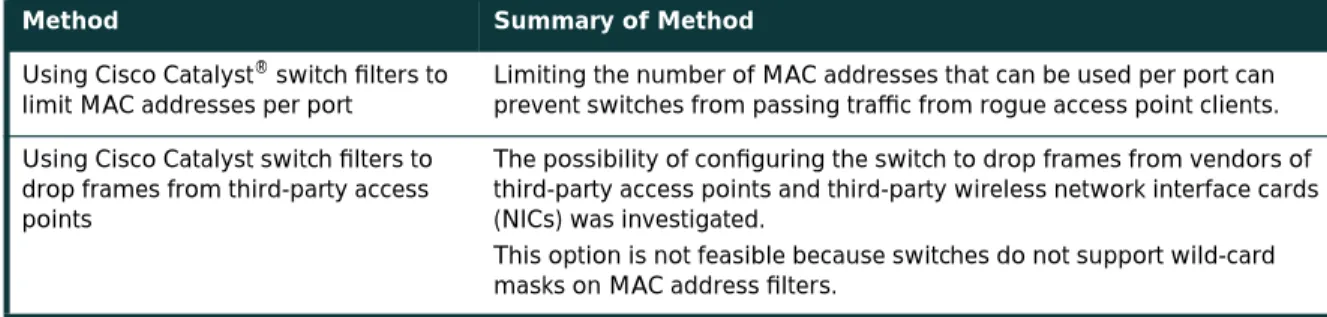
A rogue access point is one that is accessible to an organization’s employees but is not managed as a part of the trusted network. Most rogue access points are installed by employees for which IT is not providing WLAN access. A typical rogue access point, then, is an inexpensive one that an employee purchases and installs by plugging it into an available switch port, often with no security measures enabled. A hacker, even one outside the physical boundaries of an organization’s facilities, can gain access to the trusted network simply by associating with a rogue access point. Another type of rogue access point is one that masquerades as a trusted access point and tricks WLAN users into associating with it, thereby enabling a hacker to manipulate wireless frames as they cross the access point. The threat posed by rogue access points can be mitigated by preventing their deployment and detecting those rogue access points that are deployed. The following components are required in order to mitigate the threat of rogue access points. A detailed discussion of these points can be found in Appendix C, “Rogue Access Point Additional Information.”
Prevention
• Corporate policy • Physical security
• Supported WLAN infrastructure
• 802.1X port-based security on edge switches Detection
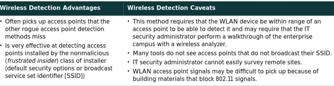
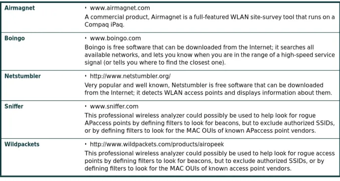
• Using wireless analyzers or sniffers
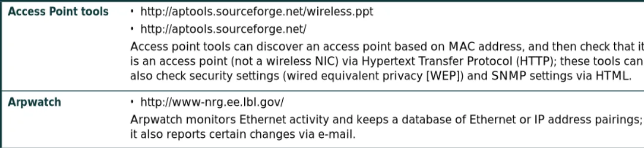
• Using scripted tools on the wired infrastructure
802.11 Is Insecure
As discussed in the primer (Appendix B), 802.11b and 802.11a are the most widely deployed WLAN technologies today. Traditional 802.11 WLAN security includes the use of open or shared-key authentication and static wired equivalent privacy (WEP) keys. This combination offers a rudimentary level of access control and privacy, but each element can be compromised. The following sections describe these elements and the challenges of their use in enterprise environments.
Authentication
The 802.11 standard supports two means of client authentication: open and shared-key authentication. Open authentication involves little more than supplying the correct service set ID (SSID). With open authentication, the use of WEP prevents the client from sending data to and receiving data from the access point, unless the client has the correct WEP key. With shared-key authentication, the access point sends the client device a challenge text packet that the client must then encrypt with the correct WEP key and return to the access point. If the client has the wrong key or no key, authentication will fail and the client will not be allowed to associate with the access point. Shared-key authentication is not considered secure because a hacker who detects both the clear text challenge and the same challenge encrypted with a WEP key can decipher the WEP key.
Key Management
Another type of key that is often used—but is not considered secure—is a “static” WEP key. A static WEP key is a key composed of either 40 or 128 bits that is statically defined by the network administrator on the access point and all clients that communicate with the access point. When static WEP keys are used, a network administrator must perform the time-consuming task of entering the same keys on every device in the WLAN.
If a device that uses static WEP keys is lost or stolen, the possessor of the stolen device can access the WLAN. An administrator will not be able to detect that an unauthorized user has infiltrated the WLAN until and unless the theft is reported. The administrator must then change the WEP key on every device that uses the same static WEP key used by the missing device. In a large enterprise WLAN with hundreds or even thousands of users, this can be a daunting task. Worse still, if a static WEP key is deciphered through a tool such as AirSnort, the administrator has no way of knowing that the key has been compromised by a hacker.
WEP
The 802.11 standards define WEP as a simple mechanism to protect the over-the-air transmission between WLAN access points and network interface cards (NICs). Working at the data link layer, WEP requires that all
communicating parties share the same secret key. To avoid conflicting with U.S. export controls that were in effect at the time the standard was developed, 40-bit encryption keys were required by IEEE 802.11b, though many vendors now support the optional 128-bit standard. WEP can be easily cracked in both 40- and 128-bit variants by using off-the-shelf tools readily available on the Internet. On a busy network, 128-bit static WEP keys can be obtained in as little as 15 minutes, according to current estimates. These attacks are described in more detail in the following paragraphs.
As mentioned in the primer (Appendix B), WEP uses the RC4 stream cipher that was invented by Ron Rivest of RSA Data Security, Inc. (RSADSI) for encryption. The RC4 encryption algorithm is a symmetric stream cipher that supports a variable-length key. The IEEE 802.11 standard describes the use of the RC4 algorithm and key in WEP, but does not specify specific methods for key distribution. Without an automated method for key distribution, any encryption protocol will have implementation problems because of the potential for human error in key input, escrow, and management. As discussed later in this document, 802.1X has been ratified in the IEEE and is being embraced by the WLAN vendor community as a potential solution for this key distribution problem.
The initialization vector is at the center of most of the issues that involve WEP. Because the initialization vector is transmitted as plaintext and placed in the 802.11 header, anyone sniffing a WLAN can see it. At 24 bits long, the initialization vector provides a range of 16,777,216 possible values. A University of California, Berkeley paper found that when the same initialization vector is used with the same key on an encrypted packet (known as an
initialization-vector collision), a hacker can capture the data frames and derive information about the data as well as the network. For more information, refer to the paper at:
http://www.isaac.cs.berkeley.edu/isaac/wep-faq.html
In the past year, encryption analysts from the University of California, Berkeley, the University of Maryland, and Cisco Systems, Inc. have reported weaknesses in the authentication and WEP encryption schemes in the IEEE 802.11 WLAN standard. These researchers have called for sophisticated key management solutions to mitigate these flaws. The University of Maryland paper can be found at:
http://www.cs.umd.edu/~waa/wireless.pdf
Cryptanalysts Fluhrer, Mantin, and Shamir (FMS) discovered inherent shortcomings with the RC4 key-scheduling algorithm. Because RC4 as implemented in WEP uses a 24-bit initialization vector and does not dynamically rotate encryption keys, these shortcomings are demonstrated to have practical applications in decrypting 802.11 frames using WEP. The attack illustrated in the paper focuses on a large class of weak initialization vectors that can be generated by RC4, and highlights methods to break the key using certain patterns in the initialization vectors. This attack is pragmatic, but the most disconcerting fact is that the attack is completely passive. In this paper, this attack is known as the FMS attack. The FMS attack discusses the theoretical derivation of a WEP key in a range of 100,000 to 1,000,000 packets encrypted using the same key. More detail can be found in the paper itself at:
http://www.cs.umd.edu/~waa/class-pubs/rc4_ksaproc.ps
Recent practical implementations of the FMS attack have been able to derive a static WEP key by capturing about a million packets. This is demonstrated in a paper by AT&T Labs and Rice University at the following URL: http://www.cs.rice.edu/~astubble/wep/wep_attack.pdf
Several independent developers then released their own implementations of the FMS attack; the most popular of these is AirSnort, which can be downloaded at the following URL:
http://airsnort.sourceforge.net/
Although traditional WLAN security that relies on open or shared keys and static WEP keys is better than no security at all, it is not sufficient for the enterprise organization. Only very small businesses, or those that do not entrust mission-critical data to their WLAN networks, can rely on these WLAN security types. All other enterprises and organizations must invest in a robust, enterprise-class WLAN security solution.
Security Extensions Are Required
Cisco agrees with the findings of the research papers discussed in the previous axiom and recommends deploying elements of the three technologies discussed in this axiom as an alternative to WEP as specified by IEEE 802.11. The technologies discussed include a network layer encryption approach based on IP security (IPsec), a mutual
authentication-based, key distribution method using 802.1X, and some proprietary improvements to WEP recently implemented by Cisco. Additionally, IEEE 802.11 Task Group “i” and the Wi-Fi Alliance compliance testing committee are working on standardizing WLAN authentication and encryption improvements.
IPsec
IPsec is a framework of open standards for ensuring secure private communications over IP networks. IPsec VPNs use the services defined within IPsec to ensure confidentiality, integrity, and authenticity of data communications across public networks, such as the Internet. IPsec also has a practical application to secure WLANs by overlaying IPsec on top of cleartext 802.11 wireless traffic.
When deploying IPsec in a WLAN environment, an IPsec client is placed on every PC connected to the wireless network and the user is required to establish an IPsec tunnel to route any traffic to the wired network. Filters are put in place to prevent any wireless traffic from reaching any destination other than the VPN gateway and Dynamic Host Configuration Protocol (DHCP) or Domain Name System (DNS) server. IPsec provides for confidentiality of IP traffic, as well as authentication and anti-replay capabilities. Confidentiality is achieved through encryption using a variant of the Data Encryption Standard (DES), called Triple DES (3DES), or the new Advanced Encryption Standard (AES).
Though IPsec is used primarily for data confidentiality and device authentication, extensions to the standard allow for user authentication and authorization to occur as part of the IPsec process. For more information on IPsec, refer to the VPN primer in the SAFE VPN paper at the following URL:
http://www.cisco.com/go/safe
802.1X/EAP
An alternative WLAN security approach focuses on developing a framework for providing centralized authentication and dynamic key distribution. This approach is based on the IEEE 802.11 Task Group “i” end-to-end framework using 802.1X and the Extensible Authentication Protocol (EAP) to provide this enhanced functionality. Cisco has incorporated 802.1X and EAP into its WLAN security solution—the Cisco Wireless Security Suite. The three main elements of an 802.1X and EAP approach follow:
• Mutual authentication between client and authentication (Remote Access Dial-In User Service [RADIUS]) server • Encryption keys dynamically derived after authentication
• Centralized policy control, where session time-out triggers reauthentication and new encryption key generation When these features are implemented, a wireless client that associates with an access point cannot gain access to the network until the user performs a network logon. After association, the client and the network (access point or RADIUS server) exchange EAP messages to perform mutual authentication, with the client verifying the RADIUS server credentials, and vice versa. An EAP supplicant is used on the client machine to obtain the user credentials (user ID and password, user ID and one-time password [OTP], or digital certificate). Upon successful client and server mutual authentication, the RADIUS server and client then derive a client-specific WEP key to be used by the client for the current logon session. User passwords and session keys are never transmitted in the clear, over the wireless link.
The sequence of events follows (refer to Figure 1): • A wireless client associates with an access point.
• The access point blocks all attempts by the client to gain access to network resources until the client logs on to the network.
• The user on the client supplies network login credentials (user ID and password, user ID and OTP, or user ID and digital certificate) via an EAP supplicant.
• Using 802.1X and EAP, the wireless client and a RADIUS server on the wired LAN perform a mutual authentication through the access point in two phases. In the first phase of EAP authentication, the RADIUS server verifies the client credentials, or vice versa. In the second phase, mutual authentication is completed by the client verifying the RADIUS server credential, or vice versa.
• When mutual authentication is successfully completed, the RADIUS server and the client determine a WEP key that is distinct to the client. The client loads this key and prepares to use it for the logon session.
• The RADIUS server sends the WEP key, called a session key, over the wired LAN to the access point.
• The access point encrypts its broadcast key with the session key and sends the encrypted key to the client, which uses the session key to decrypt it.
• The client and access point activate WEP and use the session and broadcast WEP keys for all communications during the remainder of the session or until a time-out is reached and new WEP keys are generated.
• Both the session key and broadcast key are changed at regular intervals. The RADIUS server at the end of EAP authentication specifies session key time-out to the access point and the broadcast key rotation time can be configured on the access point.
Figure 1
EAP Authentication Process
EAP provides three significant benefits over basic 802.11 security:
• The first benefit is the mutual authentication scheme, as described previously. This scheme effectively eliminates “man-in-the-middle (MITM) attacks” introduced by rogue access points and RADIUS servers.
• The second benefit is a centralized management and distribution of encryption keys. Even if the WEP
implementation of RC4 had no flaws, there would still be the administrative difficulty of distributing static keys to all the access points and clients in the network. Each time a wireless device was lost, the network would need to be rekeyed to prevent the lost system from gaining unauthorized access.
• The third benefit is the ability to define centralized policy control, where session time-out triggers reauthentication and new key derivation.
Access Point Blocks All User Requests to Access LAN
2
Client Associates with Access Point
1
User Provides Login Authentication Credentials
* Steps 4 and 5 May Be Reversed Depending Upon the EAP Type
9 Client and Access Point Activate WEP and Use Unicast and Broadcast WEP Keys for Transmission
Wireless Computer with EAP Supplicant
3
Wireless Computer with EAP Supplicant
Access Point with EAP/802.1X Support
Access Point with EAP/802.1X Support
Access Switch
Campus Network
RADIUS Server
RADIUS Server with EAP Authentication Protocols Support
and Dynamic WEP Key Generation User Database
Access Switch
Campus Network
User Database
4 RADIUS Server Authenticates User*
5 User Authenticates RADIUS Server*
6 RADIUS Server and Client Derive Unicast WEP Key
7 RADIUS Server Delivers Unicast WEP Key to Access Point
8 Access Point Delivers Broadcast WEP Key Encrypted with Unicast WEP Key to Client
EAP Authentication Protocols
Numerous EAP types are available today for user authentication over wired and wireless networks. Current EAP types include:
• EAP-Cisco Wireless (LEAP)
• EAP-Transport Layer Security (EAP-TLS) • Protected EAP (PEAP)
• EAP-Tunneled TLS (EAP-TTLS)
• EAP-Subscriber Identity Module (EAP-SIM)
In the Cisco SAFE wireless architecture, LEAP, EAP-TLS, and PEAP were tested and documented as viable mutual authentication EAP protocols for WLAN deployments.
Cisco LEAP
Cisco LEAP is the widely deployed EAP type in use today in WLANs. LEAP supports all three of the 802.1X and EAP elements mentioned previously. With LEAP, mutual authentication relies on a shared secret, the user’s logon password, which is known by the client and the network. As shown in Figure 2, the RADIUS server sends an authentication challenge to the client. The client uses a one-way hash of the user-supplied password to fashion a response to the challenge and sends that response to the RADIUS server. Using information from its user database, the RADIUS server creates its own response and compares that to the response from the client. When the RADIUS server authenticates the client, the process repeats in reverse, enabling the client to authenticate the RADIUS server. When this is complete, an EAP-Success message is sent to the client and both the client and the RADIUS server derive the dynamic WEP key.
Figure 2
LEAP Authentication Process
EAP-TLS
EAP-TLS is an Internet Engineering Task Force (IETF) standard (RFC 2716) that is based on the TLS protocol (RFC 2246). EAP-TLS uses digital certificates for both user and server authentication and supports the three key elements of 802.1X/EAP mentioned previously. As shown in Figure 3, the RADIUS server sends its certificate to the client in phase 1 of the authentication sequence (server-side TLS). The client validates the RADIUS server certificate by verifying the issuer of the certificate—a certificate authority server entity—and the contents of the digital certificate. When this is complete, the client sends its certificate to the RADIUS server in phase 2 of the authentication sequence (client-side TLS). The RADIUS server validates the client’s certificate by verifying the issuer of the certificate (certificate authority server entity) and the contents of the digital certificate. When this is complete, an EAP-Success message is sent to the client and both the client and the RADIUS server derive the dynamic WEP key.
Access Point Blocks All User Requests to Access LAN Client Associates
with Access Point
User Provides Login Authentication Credentials
7 RADIUS Server Delivers Unicast WEP Key to Access Point
Wireless Computer with Cisco LEAP Supplicant Wireless Computer with Cisco LEAP Supplicant
Access Point with Cisco LEAP
Support
Access Point with Cisco LEAP Support
Access Switch
Campus Network
RADIUS Server
RADIUS Server with LEAP Authentication Support and Dynamic WEP Key Generation
User Database
User Database
Access Switch
Campus Network
4 RADIUS Server Authenticates User
5 User Authenticates RADIUS Server
6 RADIUS Server and Client Derive Unicast WEP Key
2 1
3
8 Access Point Delivers Broadcast WEP Key Encrypted with Unicast WEP Key to Client
9 Client and Access Point Activate WEP and Use Unicast and Broadcast WEP Keys for Transmission
Figure 3
EAP-TLS Authentication Process
PEAP
PEAP is an IETF draft RFC authored by Cisco Systems, Microsoft, and RSA Security. PEAP uses a digital certificate for server authentication. For user authentication, PEAP supports various EAP-encapsulated methods within a protected TLS tunnel. PEAP supports the three main elements of 802.1X/EAP, as mentioned previously. As shown in Figure 4, phase 1 of the authentication sequence is the same as that for EAP-TLS (server-side TLS). At the end of phase 1, an encrypted TLS tunnel is created between the user and the RADIUS server for transporting EAP authentication messages. In phase 2, the RADIUS server authenticates the client through the encrypted TLS tunnel via another EAP type. As an example, a user can be authenticated using an OTP using the EAP-GTC subtype (as defined by the PEAP DRAFT). In this case, the RADIUS server will relay the OTP credentials (user ID and OTP) to an OTP server to validate the user login. When this is complete, an EAP-Success message is sent to the client and both the client and the RADIUS server derive the dynamic WEP key. For more information on PEAP, refer to the IETF Web site for the latest draft.
Access Point Blocks All User Requests to Access LAN
2
4 5
Client Associates with Access Point
1
RADIUS Server Authenticates User (via Digital Certificate) RADIUS Server and Client Derive Unicast WEP Key
7 Access Point Delivers Broadcast WEP Key Encrypted with Unicast WEP Key to Client
3 User Authenticates RADIUS Server (via Digital Certificate)
6 RADIUS Server Delivers Unicast WEP Key to Access Point
8 Client and Access Point Activate WEP and Use Unicast and Broadcast WEP Keys for Transmission
Wireless Computer with EAP-TLS
Supplicant Wireless Computer with EAP Supplicant
Access Point with EAP/802.1X
Support
Access Point with EAP/802.1X Support
Access Switch
Campus Network
RADIUS Server
RADIUS Server with EAP-TLS Authentication Support and Dynamic WEP Key Generation
User Database
User Database
Access Switch
Figure 4
PEAP Authentication Process
For more information on EAP protocols, implementation details, and guidelines for deployment over WLANs, refer to:
http://www.cisco.com/warp/public/779/smbiz/wireless/wlan_security.shtml/
WEP Enhancements
Enhancements are needed to mitigate the WEP vulnerabilities discussed in the “802.11 Is Insecure” axiom section. IEEE 802.11i includes two encryption enhancements in its draft standard for 802.11 security:
1. Temporal Key Integrity Protocol, or TKIP, which is a set of software enhancements to RC4-based WEP 2. AES, which is a stronger alternative to RC4
In December 2001, Cisco introduced support for TKIP as a component of the Cisco Wireless Security Suite. Because the standard for TKIP was not finalized at that time, the implementation is prestandard and is sometimes referred to as Cisco TKIP. In 2002, 802.11i finalized the specification for TKIP, and the Wi-Fi Alliance announced that it was making TKIP a component of Wi-Fi Protected Access (WPA), which will become a requirement for Wi-Fi compliance before the end of 2003. The enterprise version of WPA also requires 802.1X for 802.11. Both Cisco TKIP and the
Access Point Blocks All User Requests to Access LAN
2
3
Client Associates with Access Point
1
4 RADIUS Server Authenticates User (Example: OTP Authentication)
5 RADIUS Server and Client Derive Unicast WEP Key
7 Access Point Delivers Broadcast WEP Key Encrypted with Unicast WEP Key to Client Client Verifies RADIUS
Server’s Digital Certificate
6 RADIUS Server Delivers Unicast WEP Key to Access Point
8 Client and Access Point Activate WEP and Use Unicast and Broadcast WEP Keys for Transmission
Wireless Computer with PEAP Supplicant Wireless Computer with PEAP Supplicant
Access Point with PEAP Support
Access Point with PEAP Support
Access Switch
Campus Network
RADIUS Server
RADIUS Server with PEAP Authentication Support and Dynamic WEP Key Generation
User Database
User Database
Access Switch
WPA TKIP include per-packet keying (PPK) and message integrity check (MIC). WPA TKIP introduces a third element: extension of the initialization vector from 24 bits to 48 bits. This section discusses the Cisco TKIP implementation details that demonstrate the security enhancements of TKIP. For more information on WPA, refer to the WECA Web site:
http://www.weca.net
Cisco TKIP: Per-Packet Keying
Because the most popular attack against WEP relies on exploiting multiple weak initialization vectors in a stream of encrypted traffic using the same key, using different keys per packet is a potential way to mitigate the threat. As illustrated in Figure 5, the initialization vector and WEP key are hashed to produce a unique packet key (called a temporal key), which is then combined with the initialization vector and run through a mathematical function called XOR with the plaintext. The standard 802.11 method of doing the RC4 cryptography in WEP is described in the primer (Appendix B).
Figure 5
Per-Packet WEP Key Hashing
This scenario prevents the weak initialization vectors from being used to derive the base WEP key because the weak initialization vectors allow you to derive only the per-packet WEP key. In order to prevent attacks due to
initialization-vector collisions, the base key should be changed before the initialization vectors repeat. Because initialization vectors on a busy network can repeat in a matter of hours, mechanisms like EAP authentication protocols should be used to perform the rekey operation.
Similar to a unicast key, the WLAN broadcast key (used by access points and clients for Layer 2 broadcast and multicast communication) is susceptible to attacks due to initialization vector collisions. Cisco’s access points support broadcast key rotation to mitigate this vulnerability. The access point dynamically calculates the broadcast WEP key (as a function of a random number) and the new broadcast WEP key is delivered to clients using EAPOL-Key messages. Thus, broadcast WEP key rotation can be enabled only with EAP protocols such as LEAP, EAP-TLS, and PEAP that support dynamic derivation of encryption keys.
Cisco TKIP—Message Integrity Check
Another concern with WEP is its vulnerability to replay attacks. The MIC protects WEP frames from tampering. The MIC is based on a seed value, destination MAC, source MAC, and payload (that is, any changes to these will affect the MIC value). And the MIC is included in the WEP-encrypted payload. MIC uses a hashing algorithm to derive the resulting value. This is an improvement of the cyclic redundancy check (CRC)-32 checksum function as performed by standards-based WEP. With CRC-32, it is “possible to compute the bit difference of two CRCs based on the bit
HASH
RC4
XOR Ciphertext Data Packet Key
Stream Cipher IV
Plain Text Data Base Key
difference of the messages over which they are taken. In other words, flipping bit n in the message results in a deterministic set of bits in the CRC that must be flipped to produce a correct checksum on the modified message. Because flipping bits carries through after an RC4 decryption, this allows the attacker to flip arbitrary bits in an encrypted message and correctly adjust the checksum so that the resulting message appears valid.”
Summary
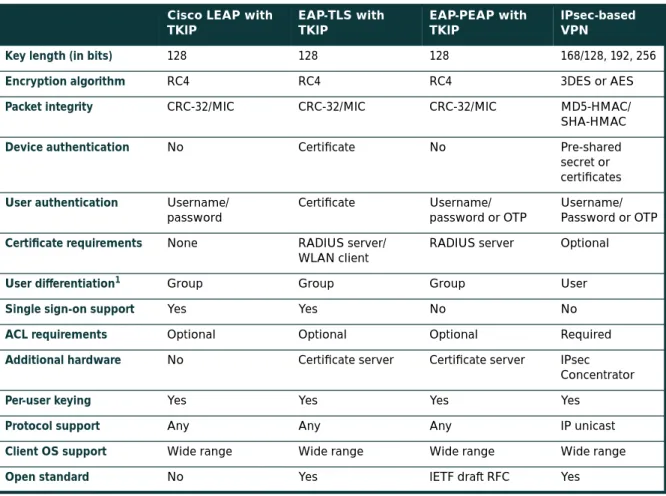
Organizations should choose to deploy either IPsec or 802.1X/EAP with TKIP or Cisco TKIP, but generally not both. Specific designs using both at the same time were tested in the SAFE lab and are discussed in the “Alternatives” sections of the following designs. Organizations should use IPsec when they have the utmost concern for the sensitivity of the transported data, but remember that this solution is more complex to deploy and manage than 802.1X/EAP with TKIP. The 802.1X/EAP with TKIP should be used when an organization wants reasonable assurance of confidentiality and a transparent user security experience. The basic WEP enhancements can be used anywhere WEP is implemented. For the vast majority of networks, the security provided by 802.1X/EAP with TKIP is sufficient. Table 1 gives a detailed view of the pros and cons of IPsec and EAP authentication protocols in WLAN designs:
Table 1 Wireless Encryption Technology Comparison Cisco LEAP with
TKIP
EAP-TLS with TKIP
EAP-PEAP with TKIP
IPsec-based VPN
Key length (in bits) 128 128 128 168/128, 192, 256
Encryption algorithm RC4 RC4 RC4 3DES or AES
Packet integrity CRC-32/MIC CRC-32/MIC CRC-32/MIC MD5-HMAC/
SHA-HMAC
Device authentication No Certificate No Pre-shared
secret or certificates User authentication Username/
password
Certificate Username/
password or OTP
Username/ Password or OTP
Certificate requirements None RADIUS server/
WLAN client
RADIUS server Optional
User differentiation1
1. User differentiation is discussed further in the section “WLAN User Differentiation.”
Group Group Group User
Single sign-on support Yes Yes No No
ACL requirements Optional Optional Optional Required
Additional hardware No Certificate server Certificate server IPsec
Concentrator
Per-user keying Yes Yes Yes Yes
Protocol support Any Any Any IP unicast
Client OS support Wide range Wide range Wide range Wide range
Network Availability Impacts Wireless
Network designers concerned about designing and implementing highly available wireless networks need to consider both the wired and wireless elements in their design. In Cisco SAFE wireless, this paper discusses only the availability requirements of the network elements that provide security-related services. Specifically, high availability is required for the following three services:
• DHCP • RADIUS • IPsec
A more detailed discussion can be found in Appendix D, “Network Availability.”
WLAN User Differentiation
In wired networks, it is often possible to segment users by community through the use of Layer 3 segmentation. In SAFE enterprise design, for example, there is a separation between a marketing segment and an R&D segment. This segmentation occurs at the building distribution module, which is the first point of Layer 3 in the network for the user community. Throughout the rest of the SAFE enterprise design, this segmentation can be maintained by filtering on the IP address that the different user communities access. Furthermore, this sort of segmentation can be administratively complex because the functional and physical separations are often two different things. For example, a financial controller with the need to access an organization’s accounting systems could be sitting next to a guest cubicle that needs access only to basic services.
Similar to the wired world, user differentiation in the wireless world can be implemented using wireless virtual LANs (VLANs) mapped to wired VLANs. Mixed deployment of security standards (802.1X/EAP and IPsec VPN) are supported through multiple VLANs, each VLAN supporting a specific security scheme. A unique wireless VLAN is identified using a unique SSID and is mapped to a wired VLAN ID. Continuing the example, the financial controller and guest use different SSIDs to obtain network access. Each SSID is mapped to a unique VLAN ID. Furthermore, VLAN access control mechanisms can be implemented using the RADIUS server. For example, the access point can dynamically map the financial controller to a VLAN ID returned by the RADIUS server upon successful 802.1X/EAP authentication. Also, the introduction of VLANs on the access point allows organizations to separate their access point management traffic from the normal flow of user traffic. Refer to Appendix A for an example implementation of user differentiation (Engineering and R&D user groups) in the enterprise EAP design. For more information on VLAN implementation on Cisco wireless platforms, refer to the “Wireless VLAN Deployment Guide” posted on Cisco.com:
http://www.cisco.com/en/US/products/hw/wireless/ps430/prod_technical_reference09186a00801444a1.html Without the implementation of wireless VLANs, IPsec-based VPN implementation can be used to enforce user-group privileges. By requiring users to run a VPN client on their end hosts, you can use the wireless network purely for transit and allow the VPN to handle any security controls. This design is discussed in detail later in the document.
Design Approach
Cisco SAFE wireless addresses the general concerns of WLAN security as outlined in the axiom section. This design section integrates the concerns and mitigation techniques of the axiom section and applies them to a variety of different networks. The size and security concerns of the specific design dictate the mitigation techniques that are applied to a WLAN design. Therefore, the network designer is offered a choice of the mitigation technology to implement along with the advantages and disadvantages of the technologies specific to the SAFE design. The mitigation technologies are consistent across all the SAFE designs, so a review of the networking elements of each of the two main technology choices is presented first. After reviewing the technologies, the network designer is presented with each SAFE design, along with the advantages and disadvantages of implementing the specific mitigation technologies within SAFE. Any unique characteristics of implementing a mitigation technology within the SAFE designs are also presented. The two main design choices follow:
• Implementing a dynamic WEP keying model using 802.1X/EAP and TKIP • Implementing an overlay VPN network using IPsec
Standard WLAN Design Guidelines
This section outlines the generic elements of WLAN designs because so many of them are common throughout the SAFE designs. After reading this section, you can move to the WLAN design that most interests you. In this way, the basic concepts can be included once, with specific variances and alternatives discussed in the specific SAFE design. In the standard WLAN designs, it is assumed that all WLAN devices are connected to a unique IP subnet to enable end-user mobility throughout various designs. An assumption is made in the designs that most services available to the wired network are also available to the wireless network addition. All designs include the following WLAN security principles:
• Access point security recommendations:
– Enable centralized user authentication (RADIUS, TACACS+) for the management interface.
– Choose strong community strings for Simple Network Management Protocol (SNMP) and change them often. – Consider using SNMP Read Only if your management infrastructure allows it.
– Disable any insecure and nonessential management protocol provided by the manufacturer. – Utilize secure management protocols, such as Secure Shell Protocol (SSH).
– Limit management traffic to a dedicated wired subnet.
– Isolate management traffic from user traffic and encrypt all management traffic where possible. – Enable wireless frame encryption where available.
– Physically secure the access point. • Client security recommendations:
– Disable ad hoc mode.
Standard EAP with TKIP WLAN Design
This design details a generic method for using EAP with TKIP as a security mechanism to access the production corporate network (refer to Figure 6).
Figure 6
Attack Mitigation Roles for Standard EAP WLAN Design
Key EAP Devices
• Wireless client adapter and software—A software solution that provides the hardware and software necessary for wireless communications to the access point; it provides mutual authentication to the access point via an EAP mutual authentication type; an EAP supplicant is required on the client machine to support the appropriate EAP authentication type
• Wireless access point—Mutually authenticates wireless clients via EAP and can support multiple Layer 2 VLANs for user differentiation
• Layer 2 or 3 switch—Provides Ethernet connectivity and Layer 3 or 4 filtering between the WLAN access point and the corporate network
• RADIUS server—Delivers user-based authentication for wireless clients and access point authentication to the wireless clients; additionally, the RADIUS server can be used to specify VLAN access control parameters for users and user groups
• DHCP server—Delivers IP configuration information for wireless LEAP clients
• OTP server (optional)—Authorizes OTP information relayed from the RADIUS server (for PEAP clients only) • PKI server (optional)—Provides X.509v3 digital certificate for user and server identification
Threats Mitigated
• Wireless packet sniffers—Wireless packet sniffers can take advantage of any of the known WEP attacks to derive the encryption key. These threats are mitigated by WEP enhancements (specifically per-packet keying as part of TKIP) (see the section “Security Extensions Are Required”), and key rotation using EAP.
• Unauthenticated access—Only authenticated users are able to access the wireless and wired network. Optional access control on the Layer 3 switch limits wired network access.
• MITM—The mutual authentication nature of several EAP authentication types combined with the MIC can prevent hackers from inserting themselves in the path of wireless communications.
Wireless Computer with EAP and TKIP
Access Point with EAP and TKIP DHCP/RADIUS/
OTP/PKI Servers
EAP Authentication Dynamic WEP Key Generation
EAP Authentication TKIP (WEP Enhancements)
Virus Scanning EAP Authentication TKIP (WEP Enhancements) Dynamic WEP Key Generation Inter Subnet
Filtering RFC 2827 Filtering
• IP spoofing—Hackers cannot perform IP spoofing without first authenticating to the WLAN, after authenticating optional RFC 2827 filtering on the Layer 3 switch restricts any spoofing to the local subnet range.
• Address Resolution Protocol (ARP) spoofing—Hackers cannot perform ARP spoofing without first
authenticating to the WLAN; after authenticating, ARP spoofing attacks can be launched in the same manner as in a wired environment to intercept other users’ data.
• Network topology discovery—Hackers cannot perform network discovery if they are unable to authenticate. The attacker can note that a WLAN network exists by looking for or observing the access point SSID, but cannot access the network. When authenticated via EAP, standard topology discovery can occur in the same way that is possible in the wired network.
Threats Not Mitigated
• Password attack—Several EAP types take into consideration that an attacker can passively monitor the 802.1X/ EAP exchanges between the client and the access point, and they mitigate this risk via various methods. PEAP mitigates this by establishing a TLS tunnel from the client to the server before asking for user authentication credentials. Also, because EAP-PEAP takes advantage of other EAP types for client-to-server authentication, the designer may choose to implement a strong authentication method such as OTP. EAP-TLS mitigates this via public key cryptography (refer to Table 2).
EAP with TKIP Design Guidelines
In most cases, WLAN access points are connected to existing Layer 2 access switches. RADIUS and DHCP servers are located in the network services module of the corporate network. Security in the design is maintained by preventing network access to unauthenticated clients, including events of a RADIUS service failure. Because most of the mitigation against security risks relies on the RADIUS service, this behavior is required. Overall, management of the solution is hindered if DHCP services fail. The wireless clients and access points use EAP to authenticate the WLAN client devices and end users against the RADIUS servers. For scalability and manageability purposes, the WLAN client devices are configured to use the DHCP protocol for IP configuration. DHCP occurs after the device and end user are successfully authenticated via an EAP protocol. After successful DHCP configuration, the wireless Table 2 WLAN Security Threat Mitigation by EAP/802.1X with TKIP Deployments
Attack Cisco LEAP with TKIP EAP-TLS with TKIP
EAP-PEAP (Client Authentication using OTP) with TKIP
MITM (active attacks) Mitigated Mitigated Mitigated
Authentication forging Mitigated Mitigated Mitigated
Passive attacks (FMS paper) Mitigated Mitigated Mitigated
Rogue access points Mitigated Mitigated Mitigated
Brute-force dictionary attacks Vulnerable1
1. Use of a strong password policy is recommended to mitigate brute-force dictionary attacks against LEAP. The IT administrator also needs to limit the number of login attempts before locking out the account.
end user is allowed access to the corporate network and filtering, if configured, occurs. Network designers should give special consideration to the location of the RADIUS and DHCP servers used by EAP in order to guarantee high availability of the network services for WLAN users.
In order to prevent attacks due to initialization vector collisions, rekeying for both unicast and broadcast keys are recommended. For EAP with Cisco TKIP, rekeying time of 4 hours and 40 minutes is recommended for both unicast and broadcast WEP keys. For more information, refer to white papers posted at:
http://www.cisco.com/warp/public/779/smbiz/wireless/wlan_security.shtml/
Additionally, the network designer should consider RADIUS server scalability in a large design. For example, server load balancing products can be used to load balance between multiple RADIUS servers in a large design.
EAP-protocol specific design guidelines follow:
• For EAP-TLS, it is recommended to use a private PKI to issue digital certificates. This allows for integration of the PKI infrastructure with existing back-end user databases (for example, Microsoft Windows 2000 AD) for certificate management.
• For EAP-TLS and EAP-PEAP, it is recommended to configure wireless clients with the trusted certificate server’s digital certificate and to prevent the normal user from modifying these settings. Only the IT administrator should have the privilege levels to modify these settings on the EAP supplicant in a wireless client. If the trusted certificate authority’s certificate was not configured, MITM attacks are possible via the use of identity spoofing.
• For EAP-LEAP and EAP-PEAP (when using static passwords), it is recommended that after a small number of incorrect login attempts, the account be locked to prevent brute-force attacks from occurring on the user account. The number of attempts is specified on the RADIUS server, and it is also recommended that these passwords be aged aggressively. The network designer can additionally mitigate this risk by requiring OTPs for client authentication.
• For EAP-TLS, it is recommended to configure the RADIUS server to check the certificate authority’s certificate revocation list (CRL) for expired client certificates.
Optionally, network designers could consider implementation of unique wireless VLANs with the EAP design. Dynamic VLAN assignment can be implemented for EAP users using the RADIUS server and user-group settings. This has the advantage of segregating wireless users into user communities and enforcing policies for these groups at the distribution layer. With the use of VLANs on access points, the management traffic can also be isolated from user traffic with the implementation of management VLAN on the access points.
Standard VPN WLAN Design
This design details a generic method for using IPsec VPNs as an overlay security mechanism to access the production corporate network from a WLAN (refer to Figure 7).
Figure 7
Attack Mitigation Roles for Standard VPN WLAN Design
Key VPN Devices
• Wireless client adapter and software—A software solution that provides the hardware and software necessary for wireless communications to the access point
• Remote-access VPN client with personal firewall software—A software client that provides end-to-end encrypted tunnels between individual PCs and the corporate wireless VPN gateways; personal firewall software provides device-level protection for individual PCs
• Wireless access point—Provides initial IP protocol filtering between the WLAN and corporate network • Layer 2 switch—Provides Ethernet connectivity between the WLAN access points and the corporate network;
additionally, recent models of access layer switches have the capability to implement a technology called VLAN ACL (VACL), which can provide an additional layer of IPsec filtering
• Layer 3 switch—Routes and switches production network data from one module to another; provides additional policy enforcement via protocol-level filtering for wireless traffic
• RADIUS server—Authenticates wireless users terminating on the VPN gateway; optionally talks to an OTP server
• OTP server—Authorizes OTP information relayed from the RADIUS server
• DHCP server—Delivers IP configuration information for wireless VPN clients before and after VPN establishment
• VPN gateway—Authenticates individual remote users and terminates their IPsec tunnels and can also provide DHCP relay functionality for wireless clients
Wireless Computer with VPN Client Access Point
with Management Interface DHCP/RADIUS/
OTP Servers
VPN Concentrator
Packet Filtering Possible Packet Filtering
(Device Dependent)
Authenticate Remote VPN Gateway Terminate IPsec
Personal Firewall for Local Attack Mitigation VPN Client Auto-Initiate
RFC 2827 Filtering Inter Subnet Filtering Two Factor
Authentication
Authenticate Remote Users Terminate IPsec
Threats Mitigated
• Wireless packet sniffers—These threats are mitigated by IPsec encryption of wireless client traffic. Also, new features in VPN client software allow the designer to specify that the VPN tunnel is automatically initiated when the correct WLAN IP address is assigned to the client. This eliminates user interaction to bring up the IPsec tunnel and also protects the client PC from broadcasting traffic onto the wireless media that could be used for inference-based attacks.
• MITM—These threats are mitigated by IPsec encryption and authentication of wireless client traffic. • Unauthorized access—The only known protocols for initial IP configuration (DHCP) and VPN access (DNS,
Internet Key Exchange [IKE], and Encapsulating Security Payload [ESP]) are allowed from the WLAN to the corporate network through filtering at the access point and access layer switch. Authorization policies can be optionally enforced on the VPN gateway for individual user groups.
• IP spoofing—Hackers can spoof traffic on the WLAN, but only valid, authenticated IPsec packets will ever reach the production wired network.
• ARP spoofing—ARP spoofing attacks can be launched; however, data is encrypted to the VPN gateway so hackers will be unable to read the data.
• Password attacks—These threats are mitigated through good password policies and auditing and optionally, OTP.
• Network topology discovery—Only IKE, ESP, DNS, and DHCP are allowed from this segment into the corporate network. Internet Control Message Protocol (ICMP) is recommended to be allowed only to the outside interface of the VPN concentrator for troubleshooting purposes.
Threats Not Mitigated
• MAC or IP spoofing from unauthenticated users—ARP spoofing and IP spoofing are still effective on the WLAN subnet until the wireless client uses IPsec to secure the connection.
Standard VPN WLAN Design Guidelines
WLAN access points connect to Layer 2 switches in the building module on a dedicated wired VLAN and forward IPsec traffic from the WLAN client. The traffic is kept separate from normal wired traffic until it is decrypted by the VPN termination device. It is important to point out that WEP is not enabled in this design. The wireless network itself is considered an untrusted network, suitable only as a transit network for IPsec traffic. In order to isolate this untrusted network, administrators should not mix the VLAN for the WLAN users with a wired network. This configuration would allow hackers on the wireless network to potentially attack users on the wired network. The WLAN clients associate with a wireless access point to establish connectivity to the campus network at Layer 2. The wireless clients then use DHCP and DNS services in the server module to establish connectivity to the campus at Layer 3. After the initial Layer 3 configuration, the VPN tunnel authenticates to the VPN gateway. The VPN gateway can use digital certificates or preshared keys for wireless device authentication. If the VPN gateway uses preshared keys for authentication, then OTPs are recommended to authenticate users to it. Without OTP, the VPN gateways are open to brute-force login attempts by hackers who have obtained the shared IPsec key used by the VPN gateway. The VPN gateway takes advantage of RADIUS services, which in turn contact the OTP server for user authentication. The VPN gateway uses DHCP for IP address configuration in order for the WLAN client to communicate through the VPN tunnel. Security in the design is maintained by preventing network access if a VPN gateway or RADIUS service fails. Both services are required in order for the client to reach the wired network with production traffic. It
should be noted that when the wireless client is communicating with the campus network, but before the IPsec tunnel is established, the client traffic is not considered secure. All the noted WLAN security issues are still present until the wireless client can secure communications with an IPsec VPN. Therefore, three mitigation techniques are
recommended:
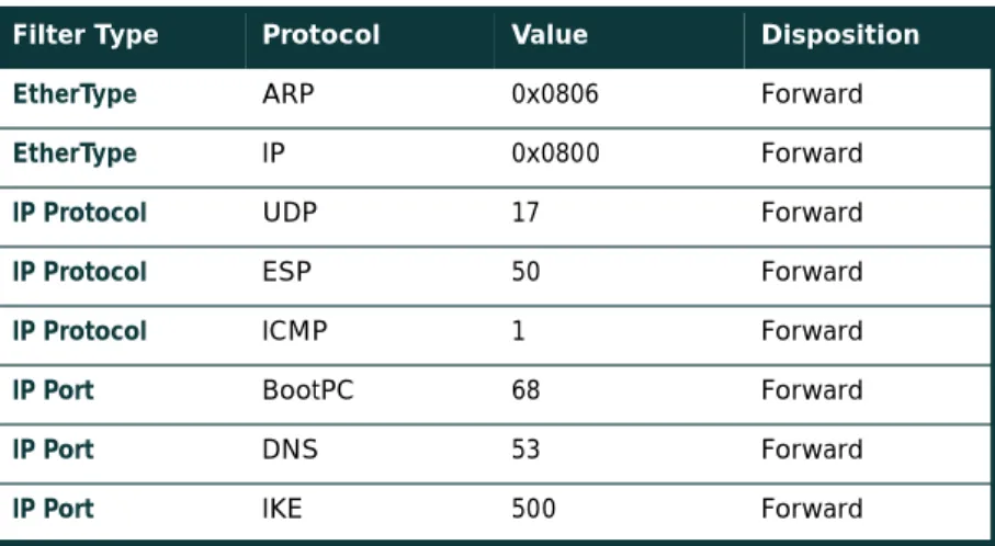
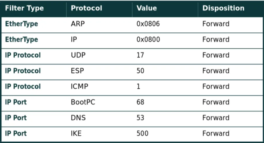
First, the access point should be configured with EtherType, protocol, and port filters based on a company's wireless usage policy. SAFE WLAN recommends restrictive filters that allow only the necessary protocols required for establishing a secure tunnel to a VPN gateway. These protocols include DHCP for initial client configuration; DNS for name resolution of the VPN gateways; the VPN-specific protocols, IKE (User Datagram Protocol [UDP] port 500) and ESP (IP Protocol 50), and ICMP for troubleshooting purposes. Even with this filtering, the DNS and DHCP servers are still open to direct attack on the application protocols themselves. Extra care should be taken to ensure that these systems are as secure as possible at the host level. This includes keeping them up-to-date with the latest OS and application patches and running a host-based intrusion detection system (HIDS). Additionally, recent models of access layer switches have the capability to implement a technology called VLAN ACL (VACL). Implementing VACLs for VPN-related protocols and specific IP addresses of the VPN concentrators can provide an additional layer of filtering to guarantee that only IPsec traffic destined for the appropriate enterprise VPN concentrators crosses the switch. The DNS traffic is optional, dependent on whether the VPN client needs to be configured with a DNS name for the VPN gateway or if only an IP address is suitable. It is recommended that ICMP be allowed only to the outside interface of the VPN concentrator for troubleshooting purposes and path maximum-transmission-unit (MTU) discovery.
Secondly, a VPN client feature automatically establishes a tunnel when the correct WLAN IP address is received from DHCP. This feature eliminates the need for the end user to manually establish the VPN tunnel after the computer startup. Third, personal firewall software is included on the wireless client to protect the client while it is connected to the untrusted WLAN network without the protection of IPsec. In general terms, the VPN gateway delineates between the trusted wired network and the untrusted WLAN. The wireless client establishes a VPN connection to the VPN gateway to start secure communication to the corporate network. In the process of doing so, the VPN gateway provides device and user authentication via the IPsec VPN. Split tunneling by the client should be disabled—all traffic must traverse the tunnel.
Alternatives
Network designers may still consider enabling static WEP keys on all devices in an effort to add an additional deterrent against hackers. The management overhead of dealing with static key changes makes this alternative less than ideal for large WLAN deployments. This management overhead could be mitigated by never changing the static WEP key, but this solution falls strongly into the “security-through-obscurity” category.
Additionally, network designers can consider using a layering of 802.1X/EAP with the IPsec-based VPN deployment to secure their WLAN environment. The primary drawback with this alternative is the necessity of managing two separate security infrastructures for WLAN deployments.
To further secure the DNS and DHCP services, network designers should consider using dedicated hosts for the VPN WLAN DHCP and DNS deployment. This mitigates against two potential threats that could affect wired resources:
• DoS attacks against the DHCP and DNS services that could affect wired users • Network reconnaissance through the use of DNS queries or reverse lookups
As an alternative to dedicated DNS servers, designers may consider hard-coding the IP address of the VPN gateway for the VPN clients. The drawback of this solution is if the IP address of the VPN gateway changes, every client will need to update his gateway entry.
Alternative WLAN Security Designs
Alternatively, network designers can also evaluate the feasibility of implementing an application layer security protocol such as Secure Socket Layer (SSL) or a tunneling protocol such as SSH in order to protect their wireless networks. To be implemented effectively in a wireless environment, the protocols need to be deployed using strong mutual authentication in order to mitigate the threat of a MITM attack. This will require the use of client-side certificates when deploying SSL to protect the application layer. Also, it should be noted that SSL is prevalent in most of the enterprise client OSs through a free browser implementation. On the other hand, SSH is not natively supported in most enterprise desktop operating systems. The network designer may have to incur a per-client cost for an SSH client. Cisco does not recommend SSL or SSH in SAFE wireless because of the limited number of technologies that can easily be secured with these protocols.
Large-Enterprise WLAN Design
The large-enterprise WLAN design overlays WLANs on top of the campus portion of the SAFE enterprise blueprint. All the components for implementing the mitigation techniques are contained within the large-enterprise building, distribution, and server modules. These components are intended to allow WLAN access for enterprise end users within the enterprise campus. Specifics for implementing each mitigation technique are discussed in detail in the following sections.
Design Guidelines
In the large-enterprise WLAN design, scalability and high availability were primary concerns when implementing the mitigation technologies. Both LEAP and VPN are considered viable security options for large-enterprise WLAN designs. Network designers should weigh the business benefits of both technologies with the company security policy before selecting the technology that is best suited for their network.
Network Management
In order to isolate management traffic from user traffic, it is recommended to use VLANs on the access points, creating a management VLAN for the access points and restricting access to the access points via the management subnet by implementing ACLs in the building distribution Layer 3 switch. The ACLs should be specific to the IP address and protocols that the centralized multidevice access point configuration tool requires. Note that because access points support only one wired interface, all management was done in band, versus the out-of-band management as recommended by SAFE enterprise. This setup contains a security risk because some management traffic (SNMP, Trivial File Transfer Protocol [TFTP], Hypertext Transfer Protocol [HTTP]) must be sent in the clear in order to manage each access point via a central management station. The access point should be configured to provide central authentication, authorization, and accounting (AAA) of access point administrators via RADIUS or TACACS+, depending on the support of the deployed access points. Finally, network administrators should utilize a secure management transport such as SSH in order to manage the access points from the command line.
EAP with TKIP Option
Figure 8Large-Enterprise EAP WLAN Design
EAP access via the wireless network takes advantage of three components from the SAFE enterprise architecture: • Building module
• Building distribution module • Server module
In the large WLAN design, the wireless access points are connected to existing Layer 2 access switches in the building module throughout the corporate campus. RADIUS OTP, PKI, and DHCP servers are located in the server module. The primary concern for EAP in a large WLAN design is the availability and scalability of the network configuration and authentication servers. Following the notes in the axiom section, the RADIUS, OTP, PKI, and DHCP servers are deployed in a redundant fashion on differing network subnets to ensure high availability and scalability. Additionally, server load balancing products can increase the scalability of the RADIUS servers by spreading the RADIUS authentication requests evenly across a farm of RADIUS servers. Beyond the notes listed previously, the connectivity method is identical to the standard EAP WLAN design discussed earlier in the document.
Wireless Computer with EAP and TKIP
To eCommerce Module
To Corporate Internet Module
To VPN/Remote Access Module To WAN Module Edge
Distribution Module Wireless Computer
with EAP and TKIP
Building Module
Core Module
Server Module
RADIUS/OTP/PKI Servers
DHCP/AP Management Servers Building
Distribution Module
Alternatives
As discussed in the general EAP design guidelines section, EAP design along with VLANs on the access points enables the network designer to implement user differentiation (using wired and wireless VLANs) and enforce VLAN assignment for users and user groups using the RADIUS server. Additionally, the network designer has the option to create a guest VLAN in order to allow guests of the enterprise access to the corporate network to gain access to a limited set of resources or VPN across the Internet to gain access to the guest’s corporate network. In either of these cases, it is recommended that the network designer implement packet filters on the access and Layer 3 building distribution switch (or wherever the guest VLAN is terminated) to allow only traffic that conforms to the enterprise guest security policy (that is, IPsec traffic only). Similarly, a VLAN can be created for traditional wireless devices that support only static WEP, and an appropriate security policy can be enforced for this VLAN as well. Refer to Appendix A for an example of implementation of EAP design with the use of VLANs on the access points.
IPsec VPN Option
Figure 9Large-Enterprise VPN WLAN Design
To eCommerce Module
To Corporate Internet Module
To VPN/Remote Access Module
To WAN Module Edge
Distribution Module VPN
Concentrator Cluster Wireless
Computer with VPN Client
Wireless Computer with VPN Client
Building Module
Core Module
Server Module
RADIUS/OTP Servers
DHCP/AP Management Servers Building
Distribution Module
![Figure A-2 illustrates the security configuration for an EAP access point. “Full Encryption” (wired equivalent privacy [WEP]) is mandated by the access point; in addition, the access point allows network EAP as the only authentication method](https://thumb-us.123doks.com/thumbv2/123dok_us/8562838.2316258/35.918.341.713.654.969/illustrates-security-configuration-encryption-equivalent-mandated-addition-authentication.webp)