AT Commands Examples
Examples for
u-blox cellular modules
Application Note
Abstract
This document provides detailed examples of how to use AT
commands with u-blox cellular modules.
UBX-13001820 - R09
Document Information
Title
AT Commands Examples
Subtitle
Examples for
u-blox cellular modules
Document type
Application Note
Document number
UBX-13001820
Revision, date
R09
17-Jul-2015
Document status
Early Production Information
Document status explanation
Objective Specification Document contains target values. Revised and supplementary data will be published later.
Advance Information Document contains data based on early testing. Revised and supplementary data will be published later. Early Production Information Document contains data from product verification. Revised and supplementary data may be published later. Production Information Document contains the final product specification.
This document applies to the following products:
Product name
LEON-G series SARA-G series LISA-U series SARA-U series TOBY-L2 series MPCI-L2 series
u-blox reserves all rights to this document and the information contained herein. Products, names, logos and designs described herein may in whole or in part be subject to intellectual property rights. Reproduction, use, modification or disclosure to third parties of this document or any part thereof without the express permission of u-blox is strictly prohibited.
The information contained herein is provided “as is” and u-blox assumes no liability for the use of the information. No warranty, either express or implied, is given, including but not limited, with respect to the accuracy, correctness, reliability and fitness for a particular purpose of the information. This document may be revised by u-blox at any time. For most recent documents, please visit
www.u-blox.com.
Contents
Contents ... 3
1
Introduction ... 7
2
AT command response parser ... 8
2.1
Handle AT command response ... 8
2.2
Handle unsolicited result code ... 9
2.3
Best practices ... 10
3
Parameters storing ... 11
4
Network registration and configuration ... 12
4.1
Steps for registering the module with a GSM/UMTS network ... 12
4.1.1
Preliminary operations ... 12
4.1.2
Network registration: GSM module ... 12
4.1.3
Network registration: UMTS module ... 13
4.1.4
Network registration: LTE module ... 18
4.1.5
Network operator configuration through +UMNOCONF AT command ... 21
4.1.6
PLMN list extension +UMNOPLMN: LTE module ... 23
4.2
Network registration flow-chart ... 24
5
GPRS connection... 27
5.1
External PDP context handling ... 27
5.1.1
External PDP context definition and activation ... 27
5.2
Internal PDP context activation ... 32
5.3
Context deactivation ... 33
5.3.1
Context deactivation by the network ... 33
5.3.2
Context deactivation by the module ... 33
5.4
Reading and setting of counters of sent and received PSD data ... 33
5.5
DoCoMo PS PUSH context manual activation ... 34
5.6
DoCoMo PS PUSH context manual reject ... 35
5.7
Data connection management ... 35
5.7.1
Network policy: only one bearer can be activated ... 36
5.7.2
Network policy: more than one bearer can be activated ... 36
5.8
Context activation in ROUTER mode ... 37
5.8.1
2G/3G case ... 37
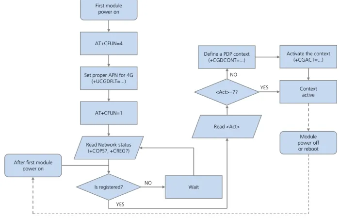
5.8.2
4G case ... 38
5.8.3
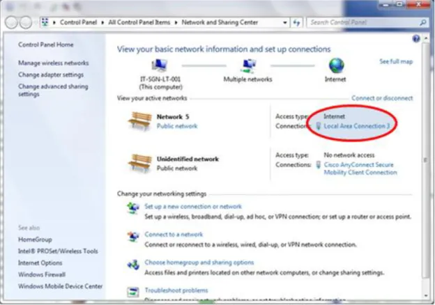
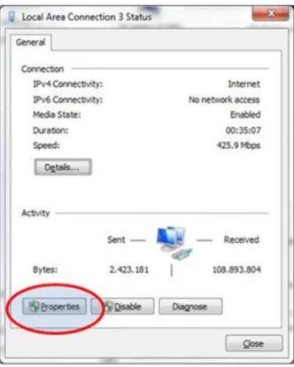
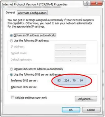
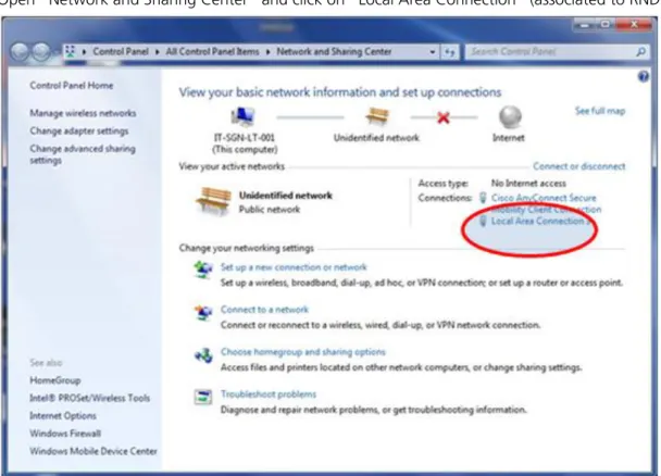
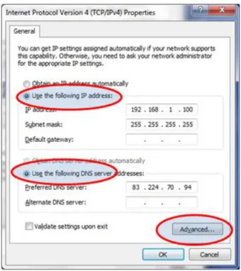
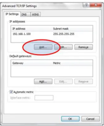
Set up the connection on Windows 7 ... 38
5.9
Context activation (BRIDGE mode) ... 42
5.9.1
2G/3G case ... 42
5.9.2
4G case ... 42
UBX-13001820 - R09 Early Production Information Contents
6
Dynamic DNS AT command ... 49
7
TCP/IP AT commands ... 49
7.1
Socket connect ... 49
7.2
Socket listening ... 50
7.3
Socket write ... 50
7.3.1
Binary mode ... 50
7.3.2
Base syntax... 51
7.3.3
Queue FULL ... 51
7.3.4
GSM network coverage lost ... 51
7.4
Socket operations with "Keep Alive" option ... 53
7.5
Socket read ... 54
7.6
Socket state ... 55
7.7
Socket close ... 56
7.8
Direct link ... 56
7.8.1
Enter and exit from Direct link mode ... 56
7.8.2
Closing a connection ... 57
7.8.3
Connection closed by remote host ... 58
7.9
Socket Always On ... 58
7.9.1
Client configuration ... 58
7.9.2
Client operation ... 58
7.9.3
Server configuration ... 59
7.9.4
Server operation ... 59
7.10
IP Change notification ... 59
7.11
Verizon socket configuration ... 60
7.12
AT&T socket configuration ... 61
8
UDP/IP AT commands ... 62
8.1
Socket write (+USOST) ... 62
8.2
Socket read (+USORF) ... 62
8.3
Socket write (+USOWR) ... 63
8.4
Socket read (+USORD) ... 64
9
FTP AT commands ... 65
9.1
Direct link ... 67
9.1.1
Retrieve a file from FTP server ... 67
9.1.2
Aborting retrieve file request ... 68
9.1.3
Store a file on FTP server ... 68
9.1.4
About "+++" escape sequence usage ... 69
9.2
Using secure option ... 69
10
SMTP AT commands ... 70
11
HTTP AT commands ... 72
11.2
HTTP POST ... 73
12
Network jamming detection AT commands ... 75
12.1
Jamming detection threshold and number of carriers evaluation ... 75
12.1.1
Example 1: 2G threshold and number of carriers evaluation ... 75
12.2
Jamming detection in 2G network ... 76
12.2.1
Example 1: all the available 2G carriers jammed ... 76
12.3
Jamming detection in 3G network ... 76
12.3.1
Example 1: all the available 3G carriers jammed ... 76
12.4
Jamming detection in 2G/3G network ... 77
12.4.1
Example 1: all the available 2G and 3G carriers jammed ... 77
12.5
Advanced jamming detection in 2G network ... 77
12.5.1
Example 1: all the available 2G carriers jammed ... 77
12.5.2
Example 2: all the available 2G carriers jammed; selected PLMN not retrieved from IMSI ... 78
12.5.3
Example 3: not jammed 2G carrier(s) are not part of the selected PLMN ... 78
13
Cell lock AT commands ... 79
13.1
Cell lock in 2G network: normal mode ... 79
13.2
Cell lock in 2G network: extended mode ... 79
13.3
Cell lock in 2G network: normal mode ... 80
13.4
Cell lock in 2G network: extended mode ... 80
13.5
Cell lock in 3G network: normal mode ... 80
13.6
Cell lock in 3G network: extended mode ... 81
13.7
Cell lock in 3G network: extended + redirection mode ... 81
13.8
Cell lock in dual-mode: normal mode ... 82
13.9
Cell lock in dual-mode: extended mode ... 82
13.10
Cell lock in dual-mode: extended + redirection mode ... 82
14
ADC AT commands ... 83
15
GPIO AT commands ... 83
16
Multiplexer AT commands ... 84
17
File system AT commands ... 85
18
SIM toolkit ... 86
18.1
Profile download ... 86
18.2
Proactive SIM ... 86
18.3
Example ... 88
18.3.1
Enable the SAT and terminal response ... 88
18.3.2
Changing the terminal profile ... 88
18.3.3
Entering SAT menu and selecting an item ... 89
18.3.4
Call setup ... 90
18.3.5
Refresh proactive command handling ... 91
UBX-13001820 - R09 Early Production Information Contents
19
SMS AT commands ... 94
19.1
Read all messages or one single message ... 94
19.2
Delete one single message or multiple messages ... 95
19.3
Write and/or send one single message ... 95
19.4
Read all messages or one single message (concatenated SMS related commands) ... 96
19.5
Write and/or send a concatenated SMS message ... 97
20
SIM lock AT commands ... 99
20.1
SIM lock activation and deactivation ... 99
20.2
SIM lock enabling and activation ... 99
21
SIM Access Profile (SAP) AT commands ... 100
21.1
SAP activation ... 100
21.2
SAP deactivation ... 101
22
USB profile configuration ... 102
22.1
High throughput profile ... 102
22.2
Fairly back-compatible profile ... 102
22.3
Low/Medium throughput profile ... 103
Appendix ... 104
A
List of acronyms ... 104
Related documents ... 106
Revision history ... 106
1
Introduction
This document provides examples of using AT commands. See
u-blox AT Commands Manual
[1] for the AT
command descriptions. The following symbols are used to highlight important information within the document:
An index finger points out key information pertaining to integration and performance.
A warning symbol indicates actions that could negatively impact or damage the module.
These icons will be used to indicate applicability to the related products:
: LEON-G series
: LISA-U series
: SARA-G series
: SARA-U series
: TOBY-L2 series
If the subsection applies to a specific product, the related icon will be provided there.
The MPCI-L2 series provides the same feature set as the TOBY-L2 series. Therefore the "TOBY-L2" icon
also refers to MPCI-L2 series.
The correctness of the networking examples depends on the availability of the website and FTP
site. Be sure to use a valid website (or FTP site).
TOBY-L2
SARA-U SARA-G LISA-U
UBX-13001820 - R09 Early Production Information AT command response parser
2
AT command response parser
The scope of this section is to give some hints about how to develop a proper AT parser and how to handle the
AT command replies and the URCs.
In this document the following naming conventions are used:
DCE (Data Communications Equipment) or MT (Mobile Terminal) is the u-blox cellular module
DTE (Data Terminal Equipment) or TE (Terminal Equipment) is the terminal that sends the command to the
module
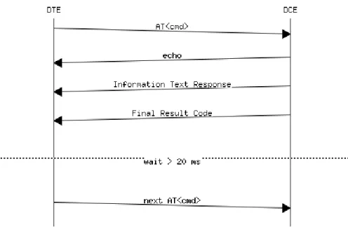
2.1
Handle AT command response
When a generic AT command is issued, depending on the command sent, there may or may not be an
Information Text Response. At the end there is always the Final Result Code, which marks the end of the
command.
The following shows responses that can occur from DTE point of view:
Wait for the command response
o
Actions to be taken when a timeout expires
Response to the command
o
OK
o
+<cmd>: ...
OK
Response to particular commands. For further details see "Information text responses and result codes"
section in the
u-blox AT Commands Manual
[1]
o
CONNECT
o
NO CARRIER
o
BUSY
o
NO ANSWER
o
CONNECT
o
>
o
@
Errors
o
+CME ERROR: ...
o
+CMS ERROR: ...
o
ERROR
Command aborted
o
ABORTED
o
OK
TOBY-L2 / MPCI-L2 modules do not support the aborting of any AT commands.
SARA-G
LEON-G
SARA-U LISA-U
TOBY-L2
SARA-U SARA-G
LISA-U
Figure 1: DTE-DCE AT command response flow chart
2.2
Handle unsolicited result code
An unsolicited result code (URC) is a string message (provided by the DCE) that is not a response to a previous
AT command. It can be output, when enabled, at any time to inform the DTE of a specific event or status
change. The URC can have the same name as the command that enables it (e.g. +CREG) or can be enabled by
another command (e.g. unsolicited result code: +CMTI, command that enables it: +CNMI).
Examples of URCs:
+<cmd>:...
RING
...
UBX-13001820 - R09 Early Production Information AT command response parser
2.3
Best practices
The DTE shall flush the AT channel (i.e. check if there are data waiting to be read) before sending a new AT
command
The DTE shall detect/process complete lines (see the S3, S4 and V0/V1 settings), so they can be processed
with a function that handles responses
The DTE shall handle the case of unexpected spaces or line endings
The DTE shall handle all the URCs: it can simply ignore them (not suggested) or, better, take a proper action
The DTE shall know what answer is expected and shall wait until it is received (i.e. final result code only or
information text response + final result code)
The final result code marks the end of an AT command and can be OK, ERROR or ABORTED: when the final
result is an error, be sure to handle it before continuing with the next AT command
The information text response format is command specific. The DTE will need explicit handling for each one.
It is suggested to consult the
u-blox AT command manual
[1]
It is suggested not to strictly parse information text responses but to check if they contain interesting
keywords and/or parameters
The DTE shall know if the issued AT command can be aborted or not
Some AT commands could output the final result code after some seconds, in this case check on AT manual
for the suggested estimated response time. If the timeout expires then a decision should be taken
accordingly: e.g. if the command can be aborted then try to abort it, etc ...
It is very useful, for debugging an application, to log all the command lines sent to the DCE and what is
received from it
Create a state machine for the AT parser (i.e. idle, waiting_response, data_mode)
The DTE shall wait some time (the recommended value is at least 20 ms) after the reception of an AT
command final response or URC before issuing a new AT command to give the module the opportunity to
transmit the buffered URCs. Otherwise the collision of the URCs with the subsequent AT command is still
possible
The DTE shall be aware that, when using a serial port without HW flow control, the first character is used to
wake up the module from power saving
3
Parameters storing
The value of some AT command parameters can be saved and retrieved either in the user profiles or in the Non
Volatile Memory (NVM) of the cellular module. For further details see the AT+CPWROFF, AT&V, AT&W, ATY
command descriptions in the
u-blox AT Commands Manual
[1].
Command Response Description
AT+CMEE=2 OK Set the verbose error result codes.
AT+UPSV=1 OK Enable the power saving.
This is an example: the power saving is not by default enabled in the default profile.
AT&Y1 OK Select the default profile that will be automatically loaded at the next hardware reset (in this example profile #1).
AT&W1 OK Store the current settings into profile 1.
AT&V ACTIVE PROFILE:
&C1, &D1, &S1, &K3, E1, Q0, V1, X4,S00:000, S02:043, S03:013, S04:010,S05:008, S07:060, +CBST:007, 000,001, +CRLP:061, 061, 048, 006, +CR:000, +CRC:000,
+IPR:0,+COPS:0,0,FFFFF, +ICF:3,1, +UPSV: 1,2000, +CMGF:0,
+CNMI:1,0,0,0,0, +USTS: 0 STORED PROFILE 0:
&C1, &D1, &S1, &K3, E1, Q0, V1,
X4,S00:000, S02:043, S03:013, S04:010, S05:008, S07:060, +CBST:007, 000, 001, +CRLP:061, 061, 048, 006,
+CR:000, +CRC:000, +IPR:0,
+COPS:0,0,FFFFF, +ICF:3,1, +UPSV: 0, +CMGF:0, +CNMI:1,0,0,0,0, +USTS: 0 STORED PROFILE 1:
&C1, &D1, &S1, &K3, E1, Q0, V1, X4, S00:000, S02:043, S03:013, S04:010, S05:008, S07:060, +CBST:007, 000, 001, +CRLP:061, 061, 048, 006, +CR:000, +CRC:000, +IPR:0, +COPS:0,0,FFFFF, +ICF:3,1, +UPSV: 1,2000, +CMGF:0, +CNMI:1,0,0,0,0, +USTS: 0
OK
Display both the current profile and the user profiles stored in memory.
This step is not mandatory.
This example refers to LEON-G series modules, different values are shown on the other u-blox modules.
AT+CSGT=1,"u-blox module" OK Set a new greeting text ("u-blox module" in this example). This is not the factory-programmed value stored in NVM.
AT+CFUN=15 OK Save the stored configuration and reboot the module without needing to switch the module off and back on.
The current configuration can be stored switching the module off through AT+CPWROFF command.
u-blox module At module power-on the greeting text is displayed.
AT+UPSV? +UPSV: 1,2000
OK
Read the current configuration of +USPV AT command. TOBY-L2 SARA-U SARA-G LISA-U LEON-G
UBX-13001820 - R09 Early Production Information Network registration and configuration
4
Network registration and configuration
4.1
Steps for registering the module with a GSM/UMTS network
Perform the module registration with GSM/UMTS network as follows:
Set the PIN
Perform the network registration
4.1.1
Preliminary operations
Command Response Description
AT+CMEE=2 OK Set the verbose error result codes. This step is not mandatory.
AT+CPIN? +CPIN: SIM PIN
OK
Check the PIN.
AT+CPIN="1234" OK Set the PIN ("1234" is an example).
AT+CPIN? +CPIN: READY
OK
Check the PIN.
OK, the PIN is ready.
4.1.2
Network registration: GSM module
4.1.2.1
Check network registration (first scenario, auto-registration)
Command Response Description
AT+COPS? +COPS: 0,0,"vodafone IT" OK
Check the network registration status.
If the first parameter is 0 then the module is registered with GSM network.
AT+CGATT? +CGATT: 1
OK
Check the GPRS attach status.
The first parameter indicates the GPRS status (in this case 1 - GPRS attached).
4.1.2.2
Check network registration (second scenario, without auto-registration)
Command Response Description
AT+COPS? +COPS: 2
OK
Check the network registration status.
If the parameter is 2 then the module is not registered with GSM network.
AT+COPS=0 OK Start the automatic network registration.
AT+COPS? +COPS: 0,0,"vodafone IT" OK
Check the network registration status.
If the first parameter is 0 then the module is registered with GSM network.
SARA-G
LEON-G
TOBY-L2
SARA-U SARA-G
LISA-U
4.1.2.3
Check network registration (third scenario, data only SIMs)
Command Response Description
AT+COPS? +COPS: 0
OK
Check the network registration status.
When using data only SIMs, in some networks AT+COPS? returns the operator name, in other networks returns only 0, even if the GPRS network registration is enabled.
AT+CREG? +CREG: 0,3
OK
Check network registration status
AT+CGREG? +CGREG: 0,1
OK
Check GPRS network registration status
AT+UCGOPS? +UCGOPS: 0,0,""00101"",2 OK
Check PS (Packet Switched) network registration status
4.1.2.4
GSM band change
Command Response Description
AT+UBANDSEL? +UBANDSEL: 900, 1800 OK
Check the current selected GSM bands.
AT+COPS=2 OK De-register the module from the network. Perform this operation only if the module is registered with the network.
AT+UBANDSEL=850,1900 OK Change the operating GSM bands.
The new configuration is saved in NVM for future registration attempts.
AT+COPS=0 OK Start the automatic network registration.
4.1.3
Network registration: UMTS module
4.1.3.1
Preliminary information about Radio Access Technology (RAT) configuration
The default RAT configuration is GSM / UMTS dual-mode, with UMTS the preferred access technology.
Command Response Description
AT+URAT? +URAT: 1,2
OK
The default RAT configuration is GSM / UMTS dual-mode Radio Access technology with UMTS preferred access technology. The module can access both GSM and UMTS networks, where UMTS is the preferred RAT.
Deregister the module from the network with
AT+COPS=2
command before changing the RAT
configuration.
Power off the module (
AT+CPWROFF
) to save the RAT configuration in the NVM. After this, switch on
the module and repeat the steps listed in section 4.1.1.
SARA-U LISA-U
UBX-13001820 - R09 Early Production Information Network registration and configuration
When a new RAT setting is saved in the NVM it is not possible to load the RAT factory-programmed
configuration. To restore this perform the following steps:
Command Response Description
AT+COPS=2 OK Deregister the module from the network. Perform this operation only if the module is registered with the network.
AT+URAT=1,2 OK Select GSM / UMTS dual-mode Radio Access technology with UMTS networks preferred.
This is the RAT factory defined configuration.
AT+CPWROFF OK Switch off the module.
4.1.3.2
RAT selection
GSM single mode RAT
Command Response Description
AT+URAT=0,0 OK Select GSM Single Mode Radio Access technology.
AT+URAT? +URAT: 0,0
OK
The module can access only GSM networks.
AT+COPS=0 OK Start automatic network registration.
AT+COPS? +COPS: 0,0,"vodafone IT",0 OK
Check the network registration status.
The last parameter describes which type of RAT (2G or 3G) the module is currently registered to (0 - GSM in this case).
GSM / UMTS dual-mode RAT
Command Response Description
AT+URAT=1,0 OK Select GSM / UMTS dual-mode Radio Access technology, GSM is the preferred access technology.
AT+URAT? +URAT: 1,0
OK
With this configuration the module can access both GSM and UMTS networks, GSM is the preferred RAT.
AT+URAT=1,2 OK Select GSM / UMTS dual-mode Radio Access technology, UMTS is the preferred RAT.
AT+URAT? +URAT: 1,2
OK
With this configuration the module can access both GSM and UMTS networks, UMTS is the preferred RAT.
AT+COPS=0 OK Start the automatic network registration.
AT+COPS? +COPS: 0,0,"vodafone IT",2 OK
Check the network registration status.
The last parameter describes which type of RAT (2G or 3G) the module is currently registered to (2 - UMTS in this case).
AT+COPS? +COPS: 0,0,"vodafone IT",0 OK
The module is also allowed to access GSM networks. This will be the information text response if it is registered with GSM service.
UMTS single mode RAT
Command Response Description
AT+URAT=2,2 OK Select UMTS Single Mode Radio Access technology.
AT+URAT? +URAT: 2,2
OK
With this configuration the module can access only UMTS networks.
Command Response Description
AT+COPS? +COPS: 0,0,"vodafone IT",2 OK
Check the network registration status.
The last parameter describes which type of RAT (2G or 3G) the module is currently registered to (2 - UMTS in this case).
If the module is registered with GSM / UMTS dual-mode (
AT+URAT=1,0
or
AT+URAT=1,2
) it is possible
to change the preferred RAT technology but the new setting only takes effect after a period of lost
network coverage or if the module is deregistered and re-registered on the network.
Command Response Description
AT+URAT=1,0 OK Select the GSM / UMTS dual-mode Radio Access technology. GSM is the preferred access technology.
AT+URAT? +URAT: 1,0
OK
With this configuration the module can access both GSM and UMTS networks, GSM networks are preferred.
AT+COPS=0 OK Start the automatic network registration.
AT+COPS? +COPS: 0,0,"vodafone IT",0 OK
Check the network registration status.
The last parameter describes which type of RAT (2G or 3G) the module is currently registered to (0 - GSM in this case).
AT+URAT=1,2 OK Select the GSM / UMTS dual-mode Radio Access technology. UMTS is the preferred access technology.
AT+URAT? +URAT: 1,2
OK
With this configuration the module can access both GSM and UMTS networks, UMTS networks are preferred.
AT+COPS? +COPS: 0,0,"vodafone IT",0 OK
The last parameter describes which type of RAT (2G or 3G) the module is currently registered to (0 - GSM in this case although UMTS is now the preferred access technology).
AT+COPS=2 OK Deregister the module from the network.
AT+COPS=0 OK Start the automatic network registration.
AT+COPS? +COPS: 0,0,"vodafone IT",2 OK
The last parameter describes which type of RAT (2G or 3G) the module is currently registered to (2 - UMTS in this case.
This is only an example. Remember that with +URAT=1,2 UMTS is the preferred and not the only allowed RAT. If the UMTS network coverage is weak the module will register again on GSM network.
AT+URAT=0,2
and
AT+URAT=2,0
are allowed but the second parameter is ignored. The second
parameter applies only to GSM / UMTS dual-mode Radio Access technology (first parameter equal to 1). In
the read command and with this setting, the second parameter of the information text response can be
omitted.
UBX-13001820 - R09 Early Production Information Network registration and configuration
4.1.3.3
UMTS band change
Command Response Description
AT+URAT?
AT+COPS? AT+UBANDSEL?
+URAT: 1,2 OK
+COPS: 0,0,"vodafone IT",2 +UBANDSEL: 2100,1900,850
Check if the module is configured in dual-mode or 3G only.
Alternative answers may be +URAT: 2,0 or URAT: 1,0.
If the module is registered, check that it is in UMTS RAT.
Check the current 3G bands.
AT+COPS=2 OK Start the automatic network registration.
AT+UBANDSEL=800,900 OK Change the operating 3G bands.
The new configuration is saved in NVM for future registration attempts.
AT+COPS=0 OK Force the network registration.
4.1.3.4
Check the device PS radio capabilities
Command Response Description
AT+UREG? +UREG: 0,0
OK
Check the current network registration status. The last parameter describes the registration status: 0 means the module is not registered for PS service.
AT+UREG? +UREG: 0,1
OK
Check the current network registration status. The last parameter describes the registration status: 1 means the module is registered for PS service and GPRS is available.
AT+UREG? +UREG: 0,2
OK
Check the current network registration status. The last parameter describes the registration status: 2 means the module is registered for PS service and EDGE is available.
AT+UREG? +UREG: 0,3
OK
Check the current network registration status. The last parameter describes the registration status: 3 means the module is registered for PS service and WCDMA is available.
AT+UREG? +UREG: 0,4
OK
Check the current network registration status. The last parameter describes the registration status: 4 means the module is registered for PS service and HSDPA is available.
AT+UREG? +UREG: 0,5
OK
Check the current network registration status. The last parameter describes the registration status: 5 means the module is registered for PS service and HSUPA is available.
AT+UREG? +UREG: 0,6
OK
Check the current network registration status. The last parameter describes the registration status: 6 means the module is registered for PS service and HSUPA and HSDPA are available.
AT+UREG=1 A network registration attach status URC can be enabled.
+UREG: 1,2 OK
The DUT generates a URC when the network attach status changes. The second parameter (2 in this example) indicates the new network registration status.
The first parameter indicates the URC status (in this case 1 - enabled) meaning URC is still enabled.
RAT configuration Operator Network registration status
+URAT: 0,0 +COPS: 0,0,"vodafone IT",0 +UREG: 0,0 +URAT: 0,0 +COPS: 0,0,"vodafone IT",0 +UREG: 0,1 +URAT: 0,0 +COPS: 0,0,"vodafone IT",0 +UREG: 0,2 +URAT: 1,0 +COPS: 0,0,"vodafone IT",0 +UREG: 0,0 +URAT: 1,0 +COPS: 0,0,"vodafone IT",0 +UREG: 0,1 +URAT: 1,0 +COPS: 0,0,"vodafone IT",0 +UREG: 0,2 +URAT: 1,0 +COPS: 0,0,"vodafone IT",2 +UREG: 0,3 +URAT: 1,0 +COPS: 0,0,"vodafone IT",2 +UREG: 0,4 +URAT: 1,0 +COPS: 0,0,"vodafone IT",2 +UREG: 0,5 +URAT: 1,0 +COPS: 0,0,"vodafone IT",2 +UREG: 0,6 +URAT: 1,2 +COPS: 0,0,"vodafone IT",2 +UREG: 0,0 +URAT: 1,2 +COPS: 0,0,"vodafone IT",0 +UREG: 0,1 +URAT: 1,2 +COPS: 0,0,"vodafone IT",0 +UREG: 0,2 +URAT: 1,2 +COPS: 0,0,"vodafone IT",2 +UREG: 0,3 +URAT: 1,2 +COPS: 0,0,"vodafone IT",2 +UREG: 0,4 +URAT: 2,2 +COPS: 0,0,"vodafone IT",2 +UREG: 0,0 +URAT: 2,2 +COPS: 0,0,"vodafone IT",2 +UREG: 0,3 +URAT: 2,2 +COPS: 0,0,"vodafone IT",2 +UREG: 0,4 +URAT: 2,2 +COPS: 0,0,"vodafone IT",2 +UREG: 0,5 +URAT: 2,2 +COPS: 0,0,"vodafone IT",2 +UREG: 0,6
UBX-13001820 - R09 Early Production Information Network registration and configuration
4.1.4
Network registration: LTE module
4.1.4.1
Preliminary information about Radio Access Technology (RAT) configuration
The default RAT configuration is tri-mode: GSM / UMTS / LTE, with LTE the preferred access technology.
Command Response Description
AT+URAT? +URAT: 4,3
OK
The default RAT configuration is GSM / UMTS / LTE tri-mode Radio Access technology with LTE as preferred access technology. The module can access both GSM, UMTS and LTE networks, where LTE is the preferred RAT.
Deregister the module from the network with the
AT+CFUN=4
command before changing the RAT
configuration.
Issue this command sequence to ensure the preferred RAT is selected after the network de-registration /
registration:
o
AT+CFUN=4
o
AT+URAT=<SelectedAcT>,<PreferredAcT>
o
AT+CFUN=1
Power off the module (
AT+CPWROFF
) to store the RAT configuration in the NVM. After this, switch on
the module and repeat the steps listed in section 4.1.1.
When a new RAT setting is saved in the NVM it is not possible to load the RAT factory-programmed
configuration. To restore this, perform the following steps:
Command Response Description
AT+CFUN=4 OK Deregister the module from the network. Perform this operation only if the module is registered with the network.
AT+URAT=4,3 OK Select GSM / UMTS / LTE tri-mode RAT with LTE networks preferred.
This is the RAT factory-programmed configuration.
AT+CPWROFF OK Switch off the module.
4.1.4.2
RAT selection
LTE single mode RAT
Command Response Description
AT+CFUN=4 OK Set the module in airplane mode.
AT+URAT=3 OK Select LTE Single Mode RAT.
AT+URAT? +URAT: 3
OK
The module can access only LTE networks.
AT+CFUN=1 OK Set the module in full functionality.
AT+COPS? +COPS: 0,0,"vodafone IT",7 OK
Check the network registration status.
The last parameter describes which type of RAT (2G, 3G or 4G) the module is currently registered to (7 – LTE in this case).
UMTS / LTE dual-mode RAT
Command Response Description
AT+CFUN=4 OK Set the module in airplane mode.
AT+URAT=6,2 OK Select UMTS / LTE dual-mode Radio Access technology, UMTS is the preferred access technology.
AT+URAT? +URAT: 6,2
OK
With this configuration the module can access both UMTS and LTE networks, UMTS is the preferred RAT.
AT+URAT=6,3 OK Select UMTS / LTE dual-mode Radio Access technology, LTE is the preferred RAT.
AT+URAT? +URAT: 6,3
OK
With this configuration the module can access both UMTS and LTE networks, LTE is the preferred RAT.
AT+CFUN=1 OK Set the module in full functionality.
AT+COPS? +COPS: 0,0,"vodafone IT",2 OK
Check the network registration status.
The last parameter describes which type of RAT (2G, 3G or 4G) the module is currently registered to (2 - UMTS in this case).
AT+COPS? +COPS: 0,0,"vodafone IT",7 OK
The module is also allowed to access LTE networks. This will be the information text response if it is registered with LTE service.
4.1.4.3
LTE band change
Command Response Description
AT+URAT? +URAT: 4,3
OK
Check how the module is configured (single, dual or tri-mode).
AT+COPS? +COPS: 0,0,"vodafone IT",7 OK
If the module is registered, check that it is in LTE RAT.
AT+UBANDSEL? +UBANDSEL: 800,850,900,1800,1 900,2100,2600
OK
Check the current 3G bands.
AT+CFUN=4 OK Set the module in airplane mode.
AT+UBANDSEL=1800,2100,2600 OK Change the operating LTE bands.
The new configuration is saved in NVM for future registration attempts.
AT+CFUN=1 OK Set the module in full functionality.
4.1.4.4
Check EPS current network registration status (CS)
Command Response Description
AT+CEREG? +CEREG: 0,1
OK
Read the EPS network registration status: the URCs are disabled and the module is registered on home PLMN.
AT+CEREG=1 OK
+CEREG: 2
Enables the URCs for EPS network registration status. The module is not registered, but it is currently trying to attach or searching an operator to register to.
AT+CEREG=2 OK
+CEREG: 1,"5A25","0099EA20",7
Enables the URCs for EPS network registration status and location information.
The module is registered on home PLMN, then follow the TAC, the cell id and the RAT.
UBX-13001820 - R09 Early Production Information Network registration and configuration
Command Response Description
AT+CEREG=3 OK
+CEREG: 1,"5A25","0099EA20",7
Enables the URCs for EPS network registration status, location information and EMM cause value information.
The module is registered on home PLMN, then follow the TAC, the cell id and the RAT. EMM info are not available.
4.1.4.5
Check EPS current network registration status (PS)
Command Response Description
AT+UREG? +UREG: 0,0
OK
Check the current network registration status. The last parameter describes the registration status: 0 means the module is not registered for PS service.
AT+UREG? +UREG: 0,1
OK
Check the current network registration status. The last parameter describes the registration status: 1 means the module is registered for PS service and GPRS is available.
AT+UREG? +UREG: 0,2
OK
Check the current network registration status. The last parameter describes the registration status: 2 means the module is registered for PS service and EDGE is available.
AT+UREG? +UREG: 0,3
OK
Check the current network registration status. The last parameter describes the registration status: 3 means the module is registered for PS service and WCDMA is available.
AT+UREG? +UREG: 0,4
OK
Check the current network registration status. The last parameter describes the registration status: 4 means the module is registered for PS service and HSDPA is available.
AT+UREG? +UREG: 0,5
OK
Check the current network registration status. The last parameter describes the registration status: 5 means the module is registered for PS service and HSUPA is available.
AT+UREG? +UREG: 0,6
OK
Check the current network registration status. The last parameter describes the registration status: 6 means the module is registered for PS service and HSUPA and HSDPA are available.
AT+UREG? +UREG: 0,7
OK
Check the current network registration status. The last parameter describes the registration status: 7 means the module is registered for PS service LTE is available.
AT+UREG=1 A network registration attach status URC can be enabled.
+UREG: 1,2 OK
The DUT generates a URC when the network attach status changes. The second parameter (2 in this example) indicates the new network registration status.
The first parameter indicates the URC status (in this case 1 - enabled) meaning URC is still enabled.
4.1.5
Network operator configuration through +UMNOCONF AT command
This section does not apply to "00S" and "50S" product versions.
This command switches between different configurations of the mobile network operators (MNO).
The MNO configuration can be manual or automatic (based on the current USIM card inserted).
4.1.5.1
Manual configuration
After a manual configuration request:
the module will de-register and de-activate the radio
the module performs all required configuration changes
the DTE is required to manually reboot the module via AT command
4.1.5.1.1
Manual regulatory configuration
Command Response Description
AT+UMNOCONF=0 OK The regulatory MNO configuration is set: IMS service is disabled, Verizon connection manager is disabled, all 4G and 3G bands are enabled.
The <conf> parameter is ignored.
AT+CFUN=16 OK Reboot the module to apply the new configuration.
4.1.5.1.2
Manual AT&T configuration
Command Response Description
AT+UMNOCONF=2 OK The AT&T configuration is set: IMS service is disabled, Verizon connection manager is disabled, 3G bands are enabled, all supported 4G bands are enabled, HSDPA category set to 14.
AT+CFUN=16 OK Reboot the module to apply the new configuration.
4.1.5.1.3
Manual Verizon configuration
Command Response Description
AT+UMNOCONF=3,7 OK The Verizon configuration is set with:
the internal connection manager active
VZWINTERNET on demand
AT+CFUN=16 OK Reboot the module to apply the new configuration.
Command Response Description
AT+UMNOCONF=3,15 OK The Verizon configuration is set with:
the internal connection manager active
IMS test mode active
AT+CFUN=16 OK Reboot the module to apply the new configuration.
UBX-13001820 - R09 Early Production Information Network registration and configuration
Command Response Description
AT+UMNOCONF=3,23 OK The Verizon configuration is set with:
the internal connection manager active
VZWINTERNET automatically handled
AT+CFUN=16 OK Module is rebooted to apply the new configuration.
4.1.5.2
Automatic configuration
After an automatic configuration request:
the module will detect the correct configuration based on SIM IMSI
if SIM is present but its IMSI is not AT&T nor Verizon then the regulatory configuration is applied
if no SIM is present then the previous valid configuration is kept
the FW will be able to handle SIM IMSI refresh (provisioning)
if a configuration change is needed then the module will de-register and de-activate the radio, perform the
required configuration changes and; issue a URC on AT terminal and optionally can perform a power cycle
after the URC has been printed.
Command Response Description
AT+UMNOCONF? +UMNOCONF:2,7 OK
TOBY-L201-01S is flashed with its FW and it is powered on without a SIM card inserted.
As expected the factory configuration is AT&T (default value)
AT+UMNOCONF=1,7 OK The module is set in automatic mode configuration.
AT+UMNOCONF? +UMNOCONF:1,7,2 As expected, no URC is printed since no valid SIM has been detected: the current configuration is kept
AT+CFUN=19 OK The protocol stack is turned off. After receiving the ‘OK’ final result code a Verizon SIM is inserted
AT+CFUN=1 OK The protocol stack is turned on
+UMNOCONF:1,7,3 A SIM has been previously inserted and the module recognizes the SIM’s IMSI.
The module is automatically reconfigured, print an URC (+UMNOCONF) and then perform a power cycle
AT+UMNOCONF? +UMNOCONF:1,7,3 OK
On next reboot the MNO configuration is checked Suppose now that for some reason the SIM becomes unreadable, in this case the module will maintain the current configuration until the SIM is replaced or until a new manual configuration is set
4.1.6
PLMN list extension +UMNOPLMN: LTE module
This section does not apply to "00S" and "50S" product versions.
This command customizes the list used by AT+UMNOCONF’s automatic SIM detection algorithm. It configures
the mapping of the current detected MNO to one of the pre-defined MNO values. It is possible to extend the
PLMN list of these MNOs:
AT&T
Verizon
Command Response Description
AT+UMNOPLMN? +UMNOPLMN: 2,"310.30,310.150, 310.170,310.280,310.380,310.4 10,310.560"
+UMNOPLMN:
3,"310.590,310.890,311.480" OK
The module is flashed with its FW and it is powered on.
This is the factory configuration.
AT+UMNOPLMN=3,"310.150" +CME ERROR: operation not
allowed "310.150" overlaps the current setting of <detectable_MNO>=2.
AT+UMNOPLMN=3,"1000.100" +CME ERROR: operation not supported
"1000.100" is not a valid PLMN id
AT+UMNOPLMN=2 OK <detectable_MNO>=2 has been reset to its factory default value
UBX-13001820 - R09 Early Production Information Network registration and configuration
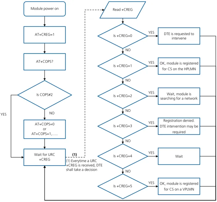
4.2
Network registration flow-chart
Figure 3 shows the suggested operations and actions for a CS and PS registration from the DTE point of view.
See the
u-blox AT Commands Manual
[1] for more detailed information about +CREG and +CGREG.
Module power on
AT+CREG=1
AT+COPS?
Is COPS≠2
NO YES
AT+COPS=0 or AT+COPS=1,…..
Wait for URC +CREG
Read +CREG
Is +CREG=0 DTE is requested to
intervene YES
(1) Everytime a URC +CREG is received, DTE shall take a decision
Is +CREG=1 OK, module is registered
for CS on the HPLMN YES
NO
Is +CREG=2 Wait, module is
searching for a network YES
Is +CREG=3
Registration denied. DTE intervention may be
required YES
NO
Is +CREG=4 YES Wait
Is +CREG=5 OK, module is registered
for CS on a VPLMN YES
NO
(1)
NO NO
Figure 3: CS and PS network registration flow chart
The suggestion is to enable +CREG and +CGREG URCs after the module power-on. In this way the DTE by
monitoring these URCs is always aware of the network status registration for the CS and PS subsystem. The
actions to be taken by DTE are similar for both +CREG and +CGREG, but the causes may be different.
When the indication +C(G)REG=5 is received, the DTE shall use +CGED to verify if the network is an
Equivalent PLMN or not, and so it can determine its roaming status.
SARA-U2 and LISA-U2 series support the Equivalent Home PLMN feature (its activation depends on the
USIM application; see the
3GPP TS 31.102
[10]). Thus the +C(G)REG=1 URC returned to DTE, may
indicate that the module is not registered on the HPLMN but on a EHPLMN.
The following is an overview of the values assumed by the <stat> parameter in +CREG:
0: a technical problem may have occurred; the user is requested to intervene. It is still possible to make
emergency calls if some network is available. Possible causes:
o
PIN not entered
o
SIM read error
o
SIM card not present
The registration is not started (+COPS=2)
1: the MT is registered on a HPLMN or an EHPLMN
2: the module is searching for a network to register on. Possible causes:
o
No network available
o
Available networks have insufficient Rx level
o
HPLMN or allowed PLMN are available but the registration is rejected, e.g. roaming is not
allowed in this Location Area
It is still possible to make emergency calls if network coverage is available.
3: the registration fails after a Location Update Reject; possible causes are:
o
Illegal MS
o
Illegal ME
o
IMSI unknown at HLR
o
PLMN not allowed
o
Location area not allowed
o
Roaming not allowed in this location area
o
Network failure
o
Network congestion
It is still possible to make emergency calls if network coverage is available.
If the registration type is manual, then no further attempt is made to search for a new PLMN or register with
it. If the registration type is automatic, the MS may look for an allowed PLMN if the rejection cause was
roaming restriction. In case of illegal MS / ME, there could be possible problems with either the SIM card or
with the MT’s identity (IMEI): user intervention may be required.
4: this value, usually transitory, is returned if the registration state does not belong to any of the following:
o
Normal
o
Limited
o
No service
o
Service detached
o
Service disabled
A failed registration procedure can be seen before starting a PLMN search, when <stat>=2.
5: the MT is registered on a VPLMN (in national/international roaming, or on an EPLMN)
The following are the recommended actions for +CGREG indications:
<stat>=0: not registered, the MT is not currently searching a new operator to register to
ACTION: send AT+COPS=0 to register, and once the module is registered (+CREG: 1), send AT+CGACT=1
to activate a new PDP context
UBX-13001820 - R09 Early Production Information Network registration and configuration
ACTION: none required, but can verify if the PDP context has been deactivated with AT+CGACT?, and if so
send AT+CGACT=0 and then AT+CGACT=1 to ensure that a new PDP context is activated
<stat>=2: not registered, but the MT is currently searching a new operator to register to
ACTION: wait for +CREG: 1, no other action required, this is the case when the module has lost network
coverage
<stat>=3 and <stat>=4: the registration is denied or unknown, it is not possible to activate a PDP context
ACTION: this may occur due to the module being unable to find signals for desired carrier, moving the
device to another location may help, otherwise suggest recalling device for repair
<stat>=5: registered, roaming
ACTION: verify if the PDP context has been deactivated with AT+CGACT?, and if so send AT+CGACT=0 and
then AT+CGACT=1 to ensure that a new PDP context is activated
Another URC which is useful for monitoring the PS status is +CGEV which can be configured via +CGEREP, for
more information see the
u-blox AT commands manual
[1]. The URC +CGEV returns information about the
GPRS mobile class, the PDP context status and the GPRS attach status.
5
GPRS connection
5.1
External PDP context handling
This section explains how to define, activate and deactivate an external Packet Data Protocol (PDP) context, i.e. a
data connection using the external IP stack (e.g. Windows dial up) and PPP over the communication port
(UART/USB).
5.1.1
External PDP context definition and activation
An external PDP context can be defined with
+CGDCONT
and then activated with
+CGACT
,
+CGDATA="PPP",
<cid> or ATD*99***<cid>#
(dial up).
The maximum number of definable PDP contexts is 3.
The +CGQREQ and +CGEQREQ (for the 3G network) commands configure the parameter <cid> that identifies
the Quality of Service (QoS) profile for the PDP context. A QoS profile can be specified after the PDP context
definition it is associated to and before its activation.
A minimum acceptable QoS profile for a PDP context may be specified with +CGQMIN and +CGEQMIN.
However, the usage of these commands should be restricted to the cases where minimum QoS parameters are
specifically constrained by the external application.
Command Response Description
AT+CGDCONT=1,"IP","web.omnitel .it"
OK Define the PDP context 1 with PDP type "IP" and APN
"web.omnitel.it".
AT+CGDCONT=3,"IP","internet" OK Define the PDP context 3 with PDP type "IP" and APN "internet".
AT+CGDCONT=2,"IP","mms.vodafon e.it"
OK Define the PDP context 2 with PDP type "IP" and APN
"mms.vodafone.it".
AT+CGDCONT? +CGDCONT: 1,"IP","web.omnitel .it","0.0.0.0",0,0
+CGDCONT: 3,"IP","internet"," 0.0.0.0",0,0
+CGDCONT: 2,"IP","mms.vodafon e.it","0.0.0.0",0,0
OK
Read the PDP contexts’ parameters.
AT+CGEQREQ=1,3,64,64,,,0,320," 1E4","1E5",1,,3
OK Define a QoS profile for PDP context 1, with Traffic
Class 3 (background), maximum bit rate 64 kb/s both for UL and for DL, no Delivery Order requirements, a maximum SDU size of 320 octets, an SDU error ratio of 10-4, a residual bit error ratio of 10-5, delivery of
erroneous SDUs allowed and Traffic Handling Priority 3.
AT+CGQREQ=2,1,3,4,5,6 OK Define a QoS profile for PDP context 2, with Precedence Class 1, Delay Class 3, Reliability Class 4, Peak Throughput Class 5 and Mean Throughput Class 6.
AT+CGACT=1,1 OK PDP context 1 activation (alternatively with AT+CGDATA="PPP", 1 or ATD*99***1#).
AT+CGPADDR=1 +CGPADDR: 1,"91.80.104.82" OK
Show address of PDP context 1. If PPP is used this command shall be sent from another AT command interface.
SARA-U LISA-U
UBX-13001820 - R09 Early Production Information GPRS connection
Command Response Description
AT+CGDCONT? +CGDCONT: 1,"IP","web.omnitel .it","91.80.104.82",0,0 +CGDCONT: 3,"IP","internet"," 0.0.0.0",0,0 +CGDCONT: 2,"IP","mms.vodafon e.it","0.0.0.0",0,0 OK
Read the PDP contexts’ parameters.
AT+CGEQNEG=1 +CGEQNEG: 1,3,64,64,0,0,0,320 ,"1E4","1E5",1,1000,3,0,0 OK
Read the negotiated QoS profile for the PDP context 1.
AT+CGACT=0,1 OK PDP context 1 deactivation.
AT+CGDCONT? +CGDCONT: 1,"IP","web.omnitel .it","0.0.0.0",0,0 +CGDCONT: 3,"IP","internet"," 0.0.0.0",0,0 +CGDCONT: 2,"IP","mms.vodafon e.it","0.0.0.0",0,0 OK
Read the PDP contexts’ parameters.
AT+CGACT=1 OK All defined PDP contexts activation.
AT+CGDCONT? +CGDCONT: 1,"IP","web.omnitel .it","91.80.101.207",0,0 +CGDCONT: 3,"IP","internet"," 83.225.114.136",0,0 +CGDCONT: 2,"IP","mms.vodafon e.it","10.159.135.60",0,0 OK
Read the PDP contexts’ parameters: all PDP contexts have different PDP addresses.
AT+CGEQNEG=2 +CGEQNEG: 2,2,128,128,0,0,0,1 500,"1E3","1E5",0,1000,3,0,0 OK
Read the negotiated QoS profile for the PDP context 2.
AT+CGACT=0 OK All defined PDP contexts deactivation.
AT+CGDCONT? +CGDCONT: 1,"IP","web.omnitel .it","0.0.0.0",0,0 +CGDCONT: 3,"IP","internet"," 0.0.0.0",0,0 +CGDCONT: 2,"IP","mms.vodafon e.it","0.0.0.0",0,0 OK
Read the PDP contexts’ parameters.
AT+CGACT=1,2 OK PDP context 2 activation.
AT+CGDCONT? +CGDCONT: 1,"IP","web.omnitel .it","0.0.0.0",0,0 +CGDCONT: 3,"IP","internet"," 0.0.0.0",0,0 +CGDCONT: 2,"IP","mms.vodafon e.it","10.153.123.229",0,0 OK
Read the PDP contexts’ parameters.
5.1.1.1
Secondary PDP context definition and activation
A secondary PDP context is an external PDP context associated with a primary external PDP context and sharing
the same PDP address and APN with it. The primary and the associated secondary PDP contexts are typically used
to provide connection to the same PDN (Packet Data Network) with different guaranteed QoS.
The typical usage of the secondary PDP contexts is in VoIP calls, where RTP (speech) packets are conveyed on one
PDP context (e.g. the primary one) with a given QoS (e.g. low reliability) whereas SIP signaling is routed on a
different PDP context (e.g. the secondary one, with the same IP address but different port numbers) with a more
reliable QoS.
The +CGDSCONT AT command defines the secondary PDP contexts. Since the maximum number of definable
PDP contexts is three, the maximum number of definable secondary PDP contexts is two.
In addition, before a secondary PDP context activation, at least one Packet Filter (PF) for a Traffic Flow Template
(TFT) must be defined with +CGTFT.
The TFT is stored by the GGSN and it is examined when routing downlink user plane data. A TFT incorporates
from one to eight PF, each characterized by a Packet Filter Identifier (PFI) and an Evaluation Precedence Index
(EPI). The EPI specifies the precedence class among all PFs associated with a PDP address. Any incoming packet is
first checked against the PF with lowest EPI and, in case no match is found, it is matched against the PF with the
next highest EPI.
A valid packet filter must contain a unique identifier (within all PFs for a given TFT) and a unique evaluation
precedence index (within all TFTs for one PDP address). If a PF is defined, with a PFI which already identifies
another PF for the same TFT, the second PF overwrites the first, so that all PFIs are unique within a TFT.
In addition, at least one of the following parameters must be included for a TFT definition:
<source_address_and_subnet_mask>
<protocol_number_(ipv4)-next_header_(ipv6)>
<destination_port_range>
<source_port_range>
<ipsec_security_parameter_index_(spi)>
<type_of_service_(tos)_(ipv4)_and_mask-traffic_class_(ipv6)_and_mask>
<flow_label (ipv6)>
The allowed combinations are:
Combination 1:
o
<source_address_and_subnet_mask>
o
<protocol_number_(ipv4)-next_header_(ipv6)>
o
<destination_port_range>
o
<source_port_range>
o
<type_of_service_(tos)_(ipv4)_and_mask-traffic_class_(ipv6)_and_mask>
Combination 2:
o
<source_address_and_subnet_mask>
o
<protocol_number_(ipv4)-next_header_(ipv6)>
o
<ipsec_security_parameter_index_(spi)>
o
<type_of_service_(tos)_(ipv4)_and_mask-traffic_class_(ipv6)_and_mask>
Combination 3:
o
<source_address_and_subnet_mask>
o
<type_of_service_(tos)_(ipv4)_and_mask-traffic_class_(ipv6)_and_mask>
o
<flow_label (ipv6)>
The secondary PDP contexts can be defined and activated as follows:
Command Response Description
AT+CGDCONT=1,"IP","web.omnite l.it"
OK Define the primary PDP context 1.
AT+CGEQREQ=1,4,32,32,,,0,320, "1E4","1E5",1,,1
OK Define a QoS profile for PDP context 1, with Traffic
Class 4 (subscribed value), maximum bit rate 32 kb/s both for UL and for DL, no Delivery Order requirements, a maximum SDU size of 320 octets, an SDU error ratio of 10-4, a residual bit error ratio of 10-5,
delivery of erroneous SDUs allowed and Traffic Handling Priority 1.
UBX-13001820 - R09 Early Production Information GPRS connection
Command Response Description
AT+CGDSCONT=2,1 OK Define a secondary PDP context with context identifier 2 associated to the primary PDP context with context identifier 1.
AT+CGEQREQ=2,3,64,64,,,0,320, "1E4","1E5",1,,2
Define a QoS profile for secondary PDP context 2, with Traffic Class 3 (background), maximum bit rate 64 kb/s both for UL and for DL, no Delivery Order requirements, a maximum SDU size of 320 octets, an SDU error ratio of 10-4, a residual bit error ratio of 10-5,
delivery of erroneous SDUs allowed and Traffic Handling Priority 2.
AT+CGDSCONT=3,1 OK Define a secondary PDP context with context identifier 3 associated to the primary PDP context with context identifier 1.
AT+CGEQREQ=3,2,64,64,,,0,320, "1E4","1E5",1,,3,,0
OK Define a QoS profile for secondary PDP context 3, with
Traffic Class 2 (Interactive), maximum bit rate 64 kb/s both for UL and for DL, no Delivery Order requirements, a maximum SDU size of 320 octets, an SDU error ratio of 10-4, a residual bit error ratio of 10-5,
delivery of erroneous SDUs allowed, and Traffic Handling Priority 3.
Since the Traffic Class is set to "Interactive" the last parameter, "Signaling Indicator", has to be specified too: in this case it is set to 0 (PDP context is not optimized for signaling).
AT+CGDCONT? +CGDCONT: 1,"IP","web.omnitel .it","0.0.0.0",0,0 +CGDCONT: 2,"IP","","0.0.0.0" ,0,0 +CGDCONT: 3,"IP","","0.0.0.0" ,0,0 OK
Read PDP contexts’ parameters.
AT+CGACT=1,2 +CME ERROR: operation not
allowed The secondary PDP context 2 cannot be activated before the primary PDP context 1 activation and before a Traffic Flow Template definition for PDP context 2 (with +CGTFT command).
AT+CGACT=1,1 OK Primary PDP context 1 activation (alternatively with AT+CGDATA="PPP", 1 or ATD*99***1#).
AT+CGDCONT? +CGDCONT: 1,"IP","web.omnitel .it","91.80.104.82",0,0 +CGDCONT: 2,"IP","","0.0.0.0" ,0,0 +CGDCONT: 3,"IP","","0.0.0.0" ,0,0 OK
Read PDP contexts’ parameters. If PPP is used this command shall be sent from another AT command interface.
AT+CGEQNEG=1 +CGEQNEG: 1,2,32,32,0,0,0,320 ,"1E4","1E5",1,1000,1,0,0 OK
Read the negotiated QoS profile for PDP context 1.
AT+CGTFT=2,1,1,"109.115.145.1 13.255.255.0.0"
OK Define a PF for PDP context 2. The packet filter
identifier is 1 (second parameter), the evaluation precedence index is 1 (third parameter).
This PF applies to all packets with source address "109.115.145.113" and subnet mask "255.255.0.0".
AT+CGTFT=2,2,3,"91.80.105.10. 255.255.0.0", ,
"65435.65535", "65235.65335"
OK Defines another PF for PDP context 2. The packet filter
identifier is 2 (second parameter), the evaluation precedence index is 3 (third parameter). This PF applies to all packets with source address "91.80.105.10", subnet mask "255.255.0.0", destination port range "65435.65535" and source port range "65235.65335".
AT+CGTFT=2,3,2,"71.40.10.10.2 55.255.0.0"
OK Defines another PF for PDP context 2. The packet filter
identifier is 3; the evaluation precedence index is 2. This PF applies to all packets with source address "71.40.10.10" and subnet mask "255.255.0.0".
Command Response Description
AT+CGACT=1,2 OK Activate secondary PDP context 2 (alternatively with AT+CGDATA="PPP", 2 or ATD*99***2#).
AT+CGDCONT? +CGDCONT: 1,"IP","web.omnitel .it","91.80.104.82",0,0 +CGDCONT: 2,"IP","","91.80.10 4.82",0,0 +CGDCONT: 3,"IP","","0.0.0.0" ,0,0 OK
Read PDP contexts’ parameters: PDP contexts 1 and 2 share the same PDP address.
AT+CGEQNEG=2 +CGEQNEG: 2,3,64,64,0,0,0,320 ,"1E4","1E5",1,1000,2,0,0 OK
Read the negotiated QoS profile for PDP context 2.
AT+CGTFT=3,4,4,"105.110.145.1 13.255.255.0.0", ,
"65435.65535", "65235.65335"
OK Defines a PF for the PDP context 3. The packet filter identifier is 4 (second parameter), the evaluation precedence index is 4 (third parameter). This PF applies to all packets with source address "105.110.145.113", subnet mask "255.255.0.0", destination port range "65435.65535" and source port range "65235.65335".
AT+CGACT=1,3 OK Activate secondary PDP context 3.
AT+CGDCONT? +CGDCONT: 1,"IP","web.omnitel .it","91.80.104.82",0,0 +CGDCONT: 2,"IP","","91.80.10 4.82",0,0 +CGDCONT: 3,"IP","","91.80.10 4.82",0,0 OK
Read PDP contexts’ parameters: all PDP contexts share the same PDP address.
AT+CGTFT=2 OK The PF for context identifier 2 becomes undefined.
AT+CGDCONT? +CGDCONT: 1,"IP","web.omnitel .it","91.80.104.82",0,0 +CGDCONT: 2,"IP","","91.80.10 4.82",0,0 +CGDCONT: 3,"IP","","91.80.10 4.82",0,0 OK
Read PDP contexts’ parameters: PDP context 2 is still active.
AT+CGACT=0,3 OK Deactivate secondary PDP context 3.
AT+CGDCONT? +CGDCONT: 1,"IP","web.omnitel .it","91.80.104.82",0,0 +CGDCONT: 2,"IP","","91.80.10 4.82",0,0 +CGDCONT: 3,"IP","","0.0.0.0" ,0,0 OK
Read PDP contexts’ parameters: PDP context 3 is not active.
AT+CGACT=0 OK Deactivate all PDP contexts.
AT+CGDCONT? +CGDCONT: 1,"IP","web.omnitel .it","",0,0 +CGDCONT: 3,"IP","","0.0.0.0" ,0,0 +CGDCONT: 2,"IP","","0.0.0.0" ,0,0 OK
Read PDP contexts’ parameters: no PDP context is active.