Product s. Technolog y. Service s. Delivered Globall y.
A Reference Guide To: ISO 11801 EN 50174 ISO 18010 ISO/IEC 24764 EN 50310 EN 50173 ANSI/TIA-568-C ANSI/TIA-606-A ANSI/TIA-942 IEEE 802.3af IEEE 802.3at IEEE 802.3an IEEE 802.3ba IEEE 802.11
F o r m o r e i n f o r m a t i o n , v i s i t w w w . a n i x t e r . c o m o r c a l l 1 . 8 0 0 . A n i x t e r
.
Anixter: The Cabling System Experts
Anixter is a leading global supplier of communications and
security products, electrical and electronic wire and cable,
fasteners and other small components. We help our customers
specify solutions and make informed purchasing decisions
around technology, applications and relevant standards.
Throughout the world, we provide innovative supply chain
management services to reduce our customers’ total cost of
production and implementation.
Purpose of Industry Standards
By providing guidelines for installation, maintenance and testing
to improve availability and reduce expenses associated with
downtime, the telecommunications standards define cabling
types, distances, connections, cable system architectures, cable
termination standards, performance characteristics, installation
and testing methods. The standards provide recommended best
practices for the design and installation of cabling systems to
support a wide variety of existing and future systems to extend
the life span of the telecommunications infrastructure. A single
common structured cabling system for all communications
and security systems simplifies moves, adds and changes,
maximises system availability and extends the usability
of a cabling system. By adhering to industry standards,
industrial environments can expect to fully experience the
benefits of structured cabling on overall performance.
Product s. Technolog y. Service s. Delivered Globall y.
Scope of this Guide
This document is meant as a reference that highlights the key points of the ISO 11801, EN 50174, ISO 18010, ISO/IEC 24764, EN 50310, EN 50173, ANSI/TIA-568-C, ANSI/TIA-606-A, ANSI/TIA-942, IEEE 802.3af, IEEE-802.3at, IEEE 802.3an, IEEE 802.3ba and IEEE 802.11 standards. It is not intended as a substitute for the original documents. For further information on any topic in the guide, refer to the actual standard. See the section called “Reference Documents” for instructions on how to order a copy of the standard itself.
Abbreviation References
ANSI American National Standards Institute
EN CENELEC
IEC International Electrotechnical Commission IEEE Institute of Electrical & Electronics Engineers ISO International Organisation for Standardisation NEC National Electrical Code
NEMA National Electrical Manufacturers Association NFPA National Fire Protection Association TIA Telecommunications Industry Association
F o r m o r e i n f o r m a t i o n , v i s i t a n i x t e r . c o m
Table of Contents
ISO/IEC 11801, Generic Cabling for Customer Premises ...3
EN 50173, Information Technology–Generic Cabling Systems ...26
EN 50173 Part 2, Installation Planning and Practices Inside Buildings ...30
ISO/IEC 18010:2002, Pathways and Spaces ...37
ISO/IEC 24764, Generic Cabling Systems for Data Centres ...42
EN 50310, Application of Equipotential Bonding and Earthing in Buildings with Information Technology Equipment ...46
ANSI/TIA-568-C.0, Generic Telecommunications Cabling for Customer Premises ...47
ANSI/TIA-606-A, Administration Standard for the Telecommunications Infrastructure of Commercial Buildings ...56
ANSI/TIA-942, Telecommunications Infrastructure Standard for Data Centres ...68
ISO 11801 Class EA (Augmented Category 6) Standard ...78
ANSI/TIA-568-C.2-ad10, Augmented Category 6 or ISO 11801 Class EA Cables ...79
IEEE 802.3af, Power over Ethernet (PoE) Standard ...80
IEEE 802.3at, Power over Ethernet+ (Plus) Standard ...80
IEEE 802.3an, Physical Layer and Management Parameters for 10 Gbps Operation, Type 10GBASE-T ...81
IEEE 802.3ba Media Access Control Parameters, Physical Layers and Management Parameters for 40 Gbps and 100 Gbps Operation ...82
IEEE 802.11, Wireless Standard ...83
The Anixter Infrastructure Solutions Lab ...85
Anixter ipAssuredSM ...88
Product s. Technolog y. Service s. Delivered Globall y.
Purpose of the ISO/IEC 11801 Standard
The international standard provides users with an application-independent generic cabling system capable of supporting a wide range of applications. It provides users with a flexible cabling scheme, so modifications are both easy and economical. Building professionals (architects, for example) are given guidance on the accommodation of cabling at the initial stages of development.The international standard specifies a multimanufacturer cabling system that may be implemented with material from single and multiple sources and is related to:
• International standards for cabling components developed by committees in the IEC
• Standards for the installation and operation of information technology cabling as well as for testing of installed cabling • Applications developed by technical committees of the IEC • Planning and installation guides that take into account
the needs of specific applications.
Generic cabling defined within this International Standard: • Specifies a cabling structure that supports a wide variety
of applications
• Specifies channel and link classes C, D, E, EA, F and FA, meeting
the requirements of standardised applications
• Specifies channel and link classes E and F based on higher performance components to support future applications • Specifies optical channel and link classes OF-300, OF-500
F o r m o r e i n f o r m a t i o n , v i s i t a n i x t e r . c o m
Cabling Subsystems
The three generic cabling systems’ subsystems include the campus backbone, building backbone and horizontal cabling. These subsystems are connected to create a generic cabling system with a structure similar to the one shown in Figure 1.
Campus backbone cabling subsystem
Generic cabling system
CD BD FD CP TO Terminal equipment Building backbone cabling subsystem Horizontal cabling subsystem Work area cabling
Figure 1 – Generic cable system diagram
Any connections between each of the subsystems are generally achieved using cross-connections by way of either patch cords or jumpers. In the case of centralised cabling, passive connections in the distributors are achieved by using cross-connections or interconnections.
Campus Subsystem (CD)
The campus backbone system connects the campus distributor to the building distributor, which is typically positioned in another building and may include the campus cables, the building entrance facility and the connecting hardware.
Building Backbone Subsystem (BD)
The building backbone system extends from the building distributor to the floor distributors. This location may include building backbone cables, jumpers, patch cords and connecting hardware.
Product s. Technolog y. Service s. Delivered Globall y.
Horizontal Cabling Subsystem (FD) and (TO)
The horizontal cabling system extends from the floor distributors to the telecommunications outlets. This may include the horizontal cabling, jumpers and patch cords in the floor distributor, mechanical terminations at the outlet and floor distributor, consolidation points and the telecommunications outlet.
Design Objectives
The campus, building backbone and horizontal cabling should be designed to support existing and emerging applications to enable the longest possible life of the system.
Incorporating Functional Elements
The CD and the FD can be located in equipment rooms or telecommunications rooms. Guidance for the accommodation of distributors is given in ISO/IEC TR 14763-2. All cables should be routed using pathways. Within the ISO/IEC 18010 standard, the requirements for the pathways and cable management are provided; these can include ducts, conduits and trays.
CD/BD TO Telecommunications room CP FD TO FD TO FD FD
F o r m o r e i n f o r m a t i o n , v i s i t a n i x t e r . c o
m
Balanced Cabling Performance
General
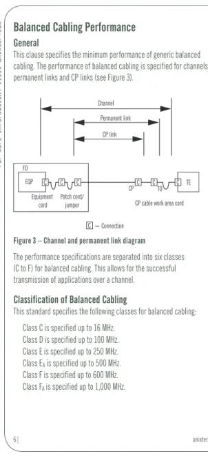
This clause specifies the minimum performance of generic balanced cabling. The performance of balanced cabling is specified for channels, permanent links and CP links (see Figure 3).
Channel
Equipment cord
= Connection Patch cord/
jumper CP cable work area cord Permanent link CP link FD CP TO EQP C C C C C TE C C
Figure 3 – Channel and permanent link diagram
The performance specifications are separated into six classes (C to F) for balanced cabling. This allows for the successful transmission of applications over a channel.
Classification of Balanced Cabling
This standard specifies the following classes for balanced cabling: Class C is specified up to 16 MHz. Class D is specified up to 100 MHz. Class E is specified up to 250 MHz. Class EA is specified up to 500 MHz. Class F is specified up to 600 MHz. Class FA is specified up to 1,000 MHz.
Product s. Technolog y. Service s. Delivered Globall y.
Return Loss
The return loss requirements are applicable only to Classes C, D, E and F.
Copper Cable Construction
The ISO standard uses a cabling scheme for the various constructions available today. The following chart defines these requirements:
Balanced element XX / XXX
TP=Twisted pair Element screen U=Unscreened
F=Foil screened Overall screen F=Foil screened S=Braid screen SF=Braid and foil screen Figure 4 – Example: F/UTP – Overall foil screened cable
with unscreened twisted pairs
Cabling Installation Requirements: Minimum Bend Radius
The minimum bend radius after installation for four-pair cables: • 25 mm for four-pair cables with a diameter up to 6 mm • 50 mm for four-pair cables with a diameter over 6 mm For minimum bending radius requirements during installation, refer to the manufacturer’s recommendations.
F o r m o r e i n f o r m a t i o n , v i s i t a n i x t e r . c o
m
Comparison between ISO 11801:2002 and
ANSI/TIA-568-C.1
The Subsystems of a Structured Cabling System
Campus Distributor (CD) and Building Entrance (BEF)
Building entrance facilities provide the point at which outdoor cabling interfaces with the intrabuilding backbone cabling. The physical requirements of the network interface are defined in the TIA-569-B standard. Refer to the EN 50174-1 standard for European specifications and ANSI/TIA-568-C.1 for U.S. specifications.
Building Distributor (BD) and Equipment Room Facility (ER)
The design aspects of the BD/ER room are specified in the TIA-569-B and EN 50174-1 standards. This room usually houses equipment of higher complexity that serves the entire building, such as servers and telecoms switches. Any or all of the functions of a floor distributor or telecommunications room may be provided by this room.
Backbone Cabling
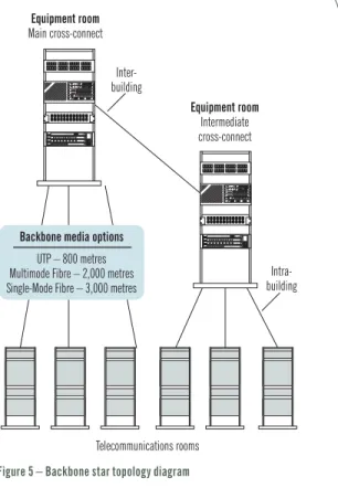
Backbone cabling provides interconnection between a floor distributor and telecommunications rooms, a building distributor and equipment rooms, and a campus distributor and entrance facilities. It consists of the backbone cables, intermediate and main cross-connects, mechanical terminations, and patch cords or jumpers used for backbone-to-backbone cross connection.
This includes:
• Vertical connection between floors (risers)
• Cables between a BD/ER and building cable entrance facility or campus distributor
Product s. Technolog y. Service s. Delivered Globall y. Telecommunications rooms Equipment room Main cross-connect Inter-building Equipment room Intermediate cross-connect
Backbone media options UTP – 800 metres Multimode Fibre – 2,000 metres Single-Mode Fibre – 3,000 metres
Intra-building
F o r m o r e i n f o r m a t i o n , v i s i t a n i x t e r . c o
m Other Design Requirements
• Star topology design.
• Implement no more than two hierarchical levels of backbone cross-connects.
• Do not install bridge taps.
• Main intermediate cross-connect or patch cord lengths shall not exceed 20 m (66 ft).
• Avoid areas with high levels of EMI or RFI.
• Meet grounding requirements as defined in the EN 50310 and J-STD-607-A standards.
Note: It is recommended that the user consults with equipment manufacturers, application standards and system providers for additional information when planning shared-sheath applications on copper backbone cables. Maximum Backbone Distances
Media Type Main to Horizontal Main to Intermediate Intermediate to Horizontal Cross-Connect Cross-Connect Cross-Connect
Copper (Voice*) 800 m (2,264 ft.) 500 m (1,640 ft.) 300 m (984 ft.) Multimode 2,000 m (6,560 ft.) 1,700 m (984 ft.) 300 m (984 ft.) Single-Mode 3,000 m (8,855 ft.) 2,700 m (8,855 ft.) 300 m (984 ft.) ISO 11801 Performance of Optical Fibre Cable
Class OF-300 channels up to 300 m Class OF-500 channels up to 500 m Class OF-2000 channels up to 2,000 m
Table 1 – Maximum backbone distances
*Note: Backbone distances are application dependent. The maximum distances specified above are based on voice transmission for UTP/ScTP and data transmission over fibre. A 90 m distance applies to UTP/ScTP. Current state-of-the-art distribution facilities usually include a combination of both copper and fibre optic cables in the backbone.
Floor Distributor (FD) and Telecommunications Room (TR)
A FD/TR room is the area within a building that houses the telecommunications cabling system equipment. This includes the mechanical terminations and/or cross-connects for the horizontal and backbone cabling system. Please refer to the ISO 11801 and TIA-569-B standards for the design specifications of the FD/TR room.
Product s. Technolog y. Service s. Delivered Globall y.
Horizontal Cabling
Specified Horizontal Cabling Topology: Star
The horizontal cabling system extends from the work area
telecommunications information outlet to the FD or TR room and consists of the following: • Horizontal cabling • Telecommunications outlet • Cable terminations • Cross connections • Patch cords
Four media types are recognised as options for horizontal cabling, each extending a maximum distance of 90 m:
• Four pair, 100 ohm UTP/ScTP cable (22–24 AWG solid conductors) • Two fibre, 62.5/125 μm or 50/125 μm optical cable
Information outlet 90 Metres 90 Metres Telecommunications room Cross-connect 100 Metres Information outlet Workstation 3 Metres
F o r m o r e i n f o r m a t i o n , v i s i t a n i x t e r . c o
m In addition to the 90 m of horizontal cable, a total of 10 m is allowed
for work area and telecommunications room patch and jumper cables.
Multiuser Telecommunications Outlet Assembly (MUTOA)
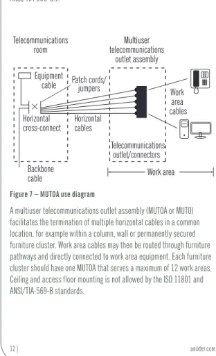
Optional practices for open office environments are specified for any horizontal telecommunications cabling recognised in ISO 11801 and ANSI/TIA-568-C.1.
Equipment
cable Patch cords/jumpers
Backbone cable Telecommunications outlet/connectors Work area cables Telecommunications
room telecommunicationsMultiuser
outlet assembly
Work area Horizontal
cross-connect Horizontalcables
Figure 7 – MUTOA use diagram
A multiuser telecommunications outlet assembly (MUTOA or MUTO) facilitates the termination of multiple horizontal cables in a common location, for example within a column, wall or permanently secured furniture cluster. Work area cables may then be routed through furniture pathways and directly connected to work area equipment. Each furniture cluster should have one MUTOA that serves a maximum of 12 work areas. Ceiling and access floor mounting is not allowed by the ISO 11801 and ANSI/TIA-569-B standards.
Product s. Technolog y. Service s. Delivered Globall y.
Maximum Work Area Cable Length is Determined by the Following Table Length of Horizontal Cable Maximum Length of Work Maximum Combined Length of m (ft.) Area Cable (24 AWG) m (ft.) Work Area Cables, Patch Cords and Equipment Cable m (ft.)
90 (295) 5 (16) 10 (33)
85 (279) 9 (30) 14 (46)
80 (262) 13 (44) 18 (59)
75 (246) 17 (57) 22 (72)
70 (230) 22 (72) 27 (89)
Table 2 – Maximum work area cable length
Note: For optical fibre, any combination of horizontal, work area cables, patch cords and equipment cords may not exceed 100 m (328 ft.).
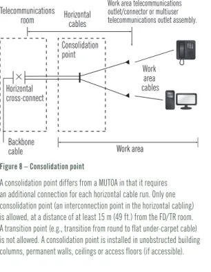
Backbone cable Consolidation point Work area cables Telecommunications Work area telecommunications outlet/connector or multiuser
telecommunications outlet assembly. room Work area Horizontal cross-connect Horizontal cables
F o r m o r e i n f o r m a t i o n , v i s i t a n i x t e r . c o
m The multiuser telecommunications outlet and consolidation point methods
are intended to be mutually exclusive. Labelling and allowance for spares is required. Moves, adds and changes should be administered in the telecom room.
Connecting Hardware Configuration
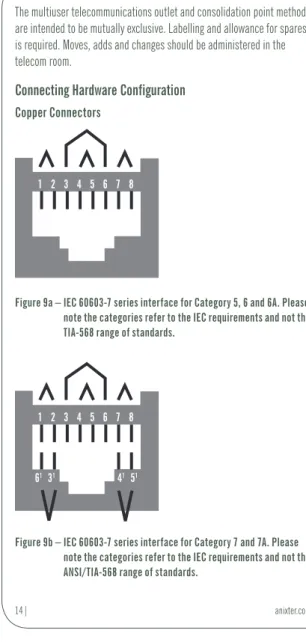
Copper Connectors
1 2 3 4 5 6 7 8
Figure 9a – IEC 60603-7 series interface for Category 5, 6 and 6A. Please note the categories refer to the IEC requirements and not the TIA-568 range of standards.
1 2 3 4 5 6 7 8
6131 41 51
Figure 9b – IEC 60603-7 series interface for Category 7 and 7A. Please note the categories refer to the IEC requirements and not the ANSI/TIA-568 range of standards.
Product s. Technolog y. Service s. Delivered Globall y. 1 2 LATCH 7 8 6 3 4 5
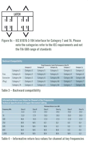
Figure 9c – IEC 61076-3-104 interface for Category 7 and 7A. Please note the categories refer to the IEC requirements and not the TIA-568 range of standards
Backward Compatibility
Fixed Connector (Jack) Performance at the TO Category 5 Category 6 Category 6A Category 7 Category 7A
Category 5 Category 5 Category 5 Category 5 Category 5 Category 5 Free Category 6 Category 5 Category 6 Category 6 Category 6 Category 6 Connector Category 6A Category 5 Category 6 Category 6A Category 6A Category 6A (Plug) Category 7 Category 5 Category 6 Category 6A Category 7 Category 7
Category 7A Category 5 Category 6 Category 6A Category 7 Category 7A
Table 3 – Backward compatibility
Informative Return Loss Values for Channel at Key Frequencies Technical Specifications of Copper Horizontal Cabling
Minimum Return Loss (dB)
Frequency MHz Class C Class D Class E Class EA Class F Class FA
1 15,0 17,0 19,0 19,0 19,0 19,0
16 15,0 17,0 18,0 18,0 18,0 18,0
100 N/A 10,0 12,0 12,0 12,0 12,0
250 N/A N/A 8,0 8,0 8,0 8,0
500 N/A N/A N/A 6,0 8,0 8,0
600 N/A N/A N/A N/A 8,0 8,0
F o r m o r e i n f o r m a t i o n , v i s i t a n i x t e r . c o m
Informative Insertion Loss Values for Channel at Key Frequencies Frequency Maximum Insertion Loss (dB)
MHz Class A Class B Class C Class D Class E Class EA Class F Class FA
0.1 6,0 5,5 N/A N/A N/A N/A N/A N/A
1 N/A 5,8 4,2 4,0 4,0 4,0 4,0 4,0
16 N/A N/A 14,4 9,1 8,3 8,2 8,1 8,0
100 N/A N/A N/A 24,0 21,7 20,9 20,8 20,3
250 N/A N/A N/A N/A 35,9 33,9 33,8 32,5
500 N/A N/A N/A N/A N/A 49,3 49,3 46,7
600 N/A N/A N/A N/A N/A N/A 54,6 51,4
1,000 N/A N/A N/A N/A N/A N/A N/A 67,6
Table 5 – Informative insertion loss values for channel at key frequencies
Informative NEXT Values for Channel at Key Frequencies Frequency Minimum Channel NEXT (dB)
MHz Class A Class B Class C Class D Class E Class EA Class F Class FA
0.1 27,0 40,0 N/A N/A N/A N/A N/A N/A
1 N/A 25,0 39,1 63,3 65,0 65,0 65,0 65,0
16 N/A N/A 19,4 43,6 53,2 53,2 65,0 65,0
100 N/A N/A N/A 30,1 39,9 39,9 62,9 65,0
250 N/A N/A N/A N/A 33,1 33,1 56,9 59,1
500 N/A N/A N/A N/A N/A 27,9 52,4 53,6
600 N/A N/A N/A N/A N/A N/A 51,2 52,1
1,000 N/A N/A N/A N/A N/A N/A N/A 47,9
Table 6 – Informative NEXT values for channel at key frequencies
Informative PS NEXT Values for Channel at Key Frequencies Minimum PS NEXT (dB) Frequency MHz Class D Class E Class EA Class F Class FA
1 60,3 62,0 62,0 62,0 62,0
16 40,6 50,6 50,6 62,0 62,0
100 27,1 37,1 37,1 59,9 62,0
250 N/A 30,2 30,2 53,9 56,1
500 N/A N/A 24,8 49,4 50,6
600 N/A N/A N/A 48,2 49,1
1,000 N/A N/A N/A N/A 44,9
Product s. Technolog y. Service s. Delivered Globall y.
Informative ACR-N Values for Channel at Key Frequencies Minimum ACR-N (dB) Frequency MHz Class D Class E Class EA Class F Class FA
1 59,3 61,0 61,0 61,0 61,0
16 34,5 44,9 45,0 56,9 57,0
100 6,1 18,2 19,0 42,1 44,7
250 N/A -2,8 -0,8 23,1 26,7
500 N/A N/A -21,4 3,1 6,9
600 N/A N/A N/A -3,4 0,7
1,000 N/A N/A N/A N/A -19,6
Table 8 – Informative ACR-N values for channel at key frequencies
Informative PS ACR-N Values for Channel at Key Frequencies Minimum PS ACR-N (dB) Frequency MHz Class D Class E Class EA Class F Class FA
1 56,3 58,0 58,0 58,0 58,0
16 31,5 42,3 42,4 53,9 54,0
100 3,1 15,4 16,2 39,1 41,7
250 N/A -5,8 -3,7 20,1 23,7
500 N/A N/A -24,5 0,1 3,9
600 N/A N/A N/A -6,4 -2,3
1,000 N/A N/A N/A N/A -22,6
Table 9 – Informative PS ACR-N values for channel at key frequencies
Informative ACR-F Values for Channel at Key Frequencies Minimum ACR-F (dB) Frequency MHz Class D Class E Class EA Class F Class FA
1 57,4 63,3 63,3 65,0 65,0
16 33,3 39,2 39,2 57,5 63,3
100 17,4 23,3 23,3 44,4 47,4
250 N/A 15,3 15,3 37,8 39,4
500 N/A N/A 9,3 32,6 33,4
600 N/A N/A N/A 31,3 31,8
F o r m o r e i n f o r m a t i o n , v i s i t a n i x t e r . c o m
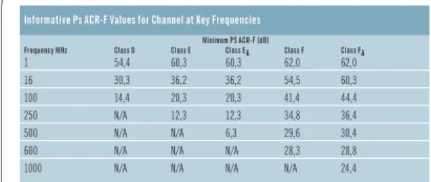
Informative Ps ACR-F Values for Channel at Key Frequencies Minimum PS ACR-F (dB)
Frequency MHz Class D Class E Class EA Class F Class FA
1 54,4 60,3 60,3 62,0 62,0
16 30,3 36,2 36,2 54,5 60,3
100 14,4 20,3 20,3 41,4 44,4
250 N/A 12,3 12,3 34,8 36,4
500 N/A N/A 6,3 29,6 30,4
600 N/A N/A N/A 28,3 28,8
1000 N/A N/A N/A N/A 24,4
Table 11 – Informative PS ACR-F values for channel at key frequencies
Informative Propagation Delay Values for Channel at Key Frequencies Frequency Minimum Propogation Delay (µs)
MHz Class A Class B Class C Class D Class E Class EA Class F Class FA
0.1 20,000 5,000 N/A N/A N/A N/A N/A N/A
1 N/A 5,000 0,580 0,580 0,580 0,580 0,580 0,580
16 N/A N/A 0,553 0,553 0,553 0,553 0,553 0,533
100 N/A N/A N/A 0,548 0,548 0,548 0,548 0,548
250 N/A N/A N/A N/A 0,546 0,546 0,546 0,546
500 N/A N/A N/A N/A N/A 0,546 0,546 0,546
600 N/A N/A N/A N/A N/A N/A 0,545 0,545
1,000 N/A N/A N/A N/A N/A N/A N/A 0,545
Table 12 – Informative propagation delay values for channel at key frequencies
Delay Skew for Channel
Class Frequency Maximum Delay Skew (µs)
A ƒ = 0.1 N/A B 0.1 ≤ ƒ ≤ 1 N/A C 1 ≤ ƒ ≤ 16 0,050 a D 1 ≤ ƒ ≤ 100 0,050 a,c E 1 ≤ ƒ ≤ 250 0,050 a,c EA 1 ≤ ƒ ≤ 500 0,050 a,c F 1 ≤ ƒ ≤ 600 0,030 b,c FA 1 ≤ ƒ ≤ 1,000 0,030 b,c a This is the result of the calculation 0,045 ÷ 4 x 0,001 25. b This is the result of the calculation 0,025 ÷ 4 x 0,001 25.
c Delay skew of the given installed cabling channel shall not vary by more than 0,010 (μs) within this requirement, due to effects such as daily temperature variations.
Products . Technology . Services . Delivered Globally .
Informative PS ANEXT Values for Channel at Key Frequencies Minimum PS ANEXT (dB) Frequency MHz Class EA Class FA
1 67,0 67,0
100 60,0 67,0
250 54,0 67,0
500 49,5 64,5
1,000 N/A 60,0
Table 14 – Informative PS ANEXT values for channel at key frequencies
Informative PS ANEXTavg values for channel at key frequencies Frequency MHz Minimum Class EA PS ANEXTavg (dB)
1 67,0
100 62,3
250 56,3
500 51,8
Table 15 – Informative PS ANEXTavg values for channel at key frequencies
Class E
A/Augmented Category 6 Channel Requirements
Note: The requirements for ISO 11801 Class EA are more demanding compared to the TIA Augmented Category 6 requirements. Anixter’s Infrastructure Solutions Lab tests to the more stringent ISO 11801 standard. ISO Compared to TIA
Characteristics 500 MHz (dB) ISO Class EA TIA Augmented Category 6
PSNEXT Loss 24,8 dB 23,2 dB
NEXT Loss 27,9 dB 26,1 dB
PSANEXT Loss 49,5 dB 49,5 dB
Return Loss 6,0 dB 6,0 dB
Insertion Loss 49,3 dB 49,3 dB
F o r m o r e i n f o r m a t i o n , v i s i t a n i x t e r . c o
m
General Information on Optical Fibre
There are six optical fibre categories that are specified to support various applications; four of these are multimode fibre (OM1, OM2, OM3, OM4) and two are single-mode fibre (OS1, OS2). The following table covers the current bandwidths available.
Cabled Optical Fibre Attenuation (Maximum) dB/km OM1, OM2, OM3
and OM4 Multimode OS1 Single-Mode OS2 Single-Mode
Wavelength 850 nm 1,300 nm 1,310 nm 1,550 nm 1,310 nm 1,383 nm 1,550 nm
Attenuation 3,5 1,5 1,0 1,0 0,4 0,4 0,4
Table 17 – Cabled optical fibre attenuation
Optical Wavelength Categories
Minimum Modal Bandwidth MHz x km Overfilled Launch Bandwidth Effective Modal Bandwidth Wavelength 850 nm 1,300 nm 850 nm Category Nominal Core Diameter (µm)
OM1 50 or 62,5 200 500 Not specified
OM2 50 or 62,5 500 500 Not specified
OM3 50 1,500 500 2,000
OM4 50 3,500 500 4,700
Note: Modal bandwidth requirements apply to the optical fibres used to produce the relevant cabled optical fibre category and are assured by the parameters and test methods specified in IEC 60793-2-10. Optical fibres that meet only the overfilled launch modal bandwidth may not support some applications specified in Annex F.
Table 18 – Optical wavelength categories
There are no bandwidth restrictions on single-mode fibre that can be measured in the field today.
Optical cables terminated in the work area shall be terminated using a duplexable LC connector that meets IEC 61754-20 for new installations. Existing connectivity can be extended.
Product s. Technolog y. Service s. Delivered Globall y.
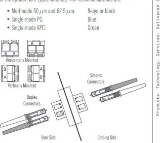
Optical Fibre Connectors
Colour coding of connectors is recommended to assist with identification of the optical fibre types installed. The recommendations are:
• Multimode 50 μm and 62.5 μm: Beige or black
• Single-mode PC: Blue
• Single-mode APC: Green
B A B A A B B A A B B A Duplex Connectors Simplex Connectors Cabling Side User Side Horizontally Mounted Vertically Mounted
Figure 10 – Duplexable LC connectivity configuration with an example of polarity identification
F o r m o r e i n f o r m a t i o n , v i s i t a n i x t e r . c o m
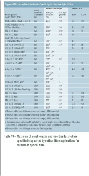
Supported Distance and Insertion Loss for Specific Applications over Optical Fibre Maximum channel length m Insertion Loss dB Nominal
transmission 50/125 µm 62,5/125 µm
Network application wavelength nm optical fibre optical fibre 50/125 62.5/125
ISO/IEC 8802-3: FOIRL 850 514 1000
ISO/IEC 8802-3:10BASE-FL and FB 850 1514 2000 6,8 12,5
ISO/IEC TR 11802-4: 4 and
16 Mbps Token Ring 850 1857 2000 8,0 13,0
ATM at 155 Mbps 850 1000b 1000a 7,2 7,2
ATM at 622 Mbps 850 300b 300a 4,0
ISO/IEC 14165-111: Fibre Channel
(FC-PH) at 1062 Mbps d 850 500b 300a 4,0
IEEE 802.3: 1000BASE-SXd 850 550b 275a 3,56 2,6
IEEE 802.3: 10GBASE-SRd 850 300c 2,6 1,6
IEEE 802.3: 40 GBASE-SR4d 850 100c, 125e
IEEE 802.3: 100GBASE-SR10d 850 100c, 125e
1 Gbps FC (1,0625 GBd)d 850 500a 300b 2,62 2 Gbps FC (2,125 GBd)d 850 300c 3,31 2,1 150b, 380c, 4 Gbps FC (4,25 GBd)d 850 400e 70 4,48 1,78 50b, 150c, 8 Gbps FC (8,5 GBd)d 850 200e2 21 2,32 1,62 35b, 100c, 16 Gbps FC (14,025 GBd)d 850 130e 15 IEEE 802.3: 100BASE-FX 1300 2000 2000
IEEE 802.5t: 100 Mbps Token Ring 1300 2000 2000
ATM at 52 Mbps 1300 2000 2000 5,3 10,0
ATM at 155 Mbps 1300 2000 2000 5,3 10,0
ATM at 622 Mbps 1300 330 500 2 6,0
IEEE 802.3: 1000BASE-LXc 1300 550b 550a 2,35 2,35
IEEE 802.3 10GBASE-LX4d 1300 300a 300a 2,0 2,0
a Minimum cabled optical fibre performance of category OM1 is specified b Minimum cabled optical fibre performance of category OM2 is specified c Minimum cabled optical fibre performance of category OM3 is specified
d These applications are bandwidth limited at the channel lengths shown. The use of lower attenuation components to produce channels exceeding the values shown cannot be recommended. e Minimum cabled optical fibre performance of OM4 is specified
Table 19 – Maximum channel lengths and insertion loss (where specified) supported by optical fibre applications for multimode optical fibre
Product s. Technolog y. Service s. Delivered Globall y.
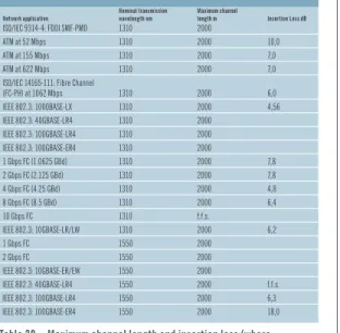
Supported Distance and Insertion Loss for Specific Applications over Optical Fibre Nominal transmission Maximum channel
Network application wavelength nm length m Insertion Loss dB
ISO/IEC 9314-4: FDDI SMF-PMD 1310 2000
ATM at 52 Mbps 1310 2000 10,0
ATM at 155 Mbps 1310 2000 7,0
ATM at 622 Mbps 1310 2000 7,0
ISO/IEC 14165-111: Fibre Channel
(FC-PH) at 1062 Mbps 1310 2000 6,0 IEEE 802.3: 1000BASE-LX 1310 2000 4,56 IEEE 802.3: 40GBASE-LR4 1310 2000 IEEE 802.3: 100GBASE-LR4 1310 2000 IEEE 802.3: 100GBASE-ER4 1310 2000 1 Gbps FC (1.0625 GBd) 1310 2000 7,8 2 Gbps FC (2.125 GBd) 1310 2000 7,8 4 Gbps FC (4.25 GBd) 1310 2000 4,8 8 Gbps FC (8.5 GBd) 1310 2000 6,4 10 Gbps FC 1310 f.f.s. IEEE 802.3: 10GBASE-LR/LW 1310 2000 6,2 1 Gbps FC 1550 2000 2 Gbps FC 1550 2000 IEEE 802.3: 10GBASE-ER/EW 1550 2000 IEEE 802.3: 40GBASE-LR4 1550 2000 f.f.s. IEEE 802.3: 100GBASE-LR4 1550 2000 6,3 IEEE 802.3: 100GBASE-ER4 1550 2000 18,0
Table 20 – Maximum channel length and insertion loss (where specified) supported by optical fibre applications for single-mode optical fibre.
Note: EN 50173 published across Europe is harmonised with the ISO 11801 standard.
F o r m o r e i n f o r m a t i o n , v i s i t a n i x t e r . c o
m
Definitions of Electrical Parameters
Return loss: A measure of the degree of impedance mismatch between two impedances. It is the ratio, expressed in decibels, of the amplitude of a reflected wave echo to the amplitude of the main wave at the junction of a transmission line and a terminating impedance.
Insertion loss: This term has replaced the term “attenuation” (ATTN). It is a measure of the decrease of signal strength as it travels down the media.
NEXT loss (near-end crosstalk): A measure of the unwanted signal coupling from a transmitter at the near-end into a neighbouring (nonenergised) pair measured at the near-end.
PSNEXT loss (powersum near-end crosstalk): A computation of the unwanted signal coupling from multiple transmitters at the near-end into a neighbouring (nonenergised) pair measured at the near-end.
FEXT loss (far-end crosstalk): A measure of the unwanted signal coupling from a transmitter at the near-end into a neighbouring pair measured at the far-end.
ACRF (attenuation to crosstalk ratio, far-end) or ELFEXT (equal-level far-end crosstalk): A measure of the unwanted signal coupling from a transmitter at the near-end into a neighbouring pair measured at the far-end, relative to the received signal level measured on that same pair.
PSFEXT loss (powersum far-end crosstalk): A computation of the unwanted signal coupling from multiple transmitters at the near-end into a neighbouring pair measured at the far-end.
PSACRF (powersum attenuation to crosstalk ratio, far-end) or PSELFEXT (powersum equal-level far-end crosstalk): A computation of the unwanted signal coupling from multiple transmitters at the near-end into a neighbouring pair measured at the far-end, relative to the received signal level measured on that same pair.
Propagation delay: The time needed for the transmission of signal to travel the length of a single pair.
Product s. Technolog y. Service s. Delivered Globall y.
Propagation delay skew: The difference between the propagation delay of any two pairs within the same cable sheath. Delay skew is caused primarily because twisted-pair cable is designed to have different twists per foot (lay lengths). Delay skew could cause data transmitted over one wire pair to arrive out of sync with data over another wire pair.
ANEXT loss (alien near-end crosstalk): A measure of signal coupling from a near-end disturbing pair into a disturbed pair of a neighbouring cable or connector pair or part thereof, measured at the near-end.
PSANEXT loss (powersum alien near-end crosstalk): A computation of signal coupling from multiple near-end disturbing pairs into a disturbed pair of a neighbouring channel, cable or connector pair or part thereof, measured at the near-end.
AFEXT loss (alien far-end crosstalk): A measure of signal coupling from a near-end disturbing pair into a disturbed pair of a neighbouring cable or connector pair or part thereof, measured at the far-end.
PSAFEXT loss (powersum alien far-end crosstalk): A computation of signal coupling from multiple near-end disturbing channel pairs into a disturbed pair of a neighbouring channel or part thereof, measured at the far-end.
PSAACRF (powersum alien attenuation to crosstalk ratio, far-end) or PSAELFEXT (powersum alien equal-level far-end crosstalk): A computation of signal coupling from multiple pairs of disturbing channels to a disturbed pair in another channel measured at the far-end and relative to the received signal level in the disturbed pair at the far-end.
F o r m o r e i n f o r m a t i o n , v i s i t a n i x t e r . c o
m
Purpose of the EN 50173 Standard
This group of European standards specifies:
• The structure and configuration of the backbone cabling subsystems of generic cabling systems within the types of premises defined by the EN 50173 series of standards • Channel performance requirements in support
of the EN 50173 series of standards • Link performance requirements in support
of the EN 50173 series of standards
• Backbone cabling reference implementations in support of the standards in the EN 50173 series
• Component performance requirements in support of the standards in the EN 50173 series.
Part 1 of the 50173 family of standard covers the requirements of the environment that the cable is to be installed. This requirement is know today as the MICE designation and refers to the local conditions that the cabling components are to be exposed. With regard to temperature, the local environment is considered to be the operating temperature of the cabling.
Product s. Technolog y. Service s. Delivered Globall y.
Section Contents
EN 50173
Information Technology–Generic Cabling Systems
Environmental Requirements ... 28 Industrial Areas ... 28
F o r m o r e i n f o r m a t i o n , v i s i t a n i x t e r . c o m
EN 50173 Information Technology –
Generic Cabling Systems
Part 1 of the 50173 family of standards covers the environmental requirements of the location where the cable is to be installed. This requirement is known today as the MICE designation, which refers to the local conditions that the cabling components are to be exposed. With regard to temperature, the local environment is considered to be the operating temperature of the cabling.
Environmental Requirements
Mechanical M1 M2 M3 Ingress rating I1 I2 I3 Climatic C1 C2 C3 Electromagnetic E1 E2 E3 Classes Increasing severityThe MICE matrix defines environmental classes in three levels and four parameters.
Legend
M1I1C1E1 describes a worst-case environment according
to ISO/IEC 11801
M2I2C2E2 describes a worst-case light industrial environment
M3I3C3E3 describes a worst-case industrial environment The MICE concept is based on the assumption that cabling, even under
the worst conditions of an environmental class, is still protected and helps to guarantee reliable network operation. Figure 11 – MICE designation
Industrial Areas
Industrial premises cabling may traverse from the front office through the factory floor. The factory floor may include work areas and automation islands. Typically, industrial premises encompass environments that are much harsher when compared to commercial office environments.
Product s. Technolog y. Service s. Delivered Globall y.
As such, additional performance requirements for industrial-premises telecommunications components must be considered.
Figure 12 – Typical industrial environment
For further information on the MICE environmental requirements, please refer to the EN 50173-1:2007+A1:2009. Information Technology-Generic Cabling Systems-General requirements.
30| anixter.com F o r m o r e i n f o r m a t i o n , v i s i t a n i x t e r . c o
m
Purpose of the EN 50173 Standard Part 2
EN 50174-2 and EN 50174-3 are intended to be used by the personnel directly involved in the planning aspects of the specification phase and installation phase. EN 50174-2 is applicable inside buildings and EN 50174-3 is applicable outside buildings.
This European standard is also relevant to: • Architects, building designers and builders • Main contractors
• Designers, suppliers, installers, inspectors (auditors), maintainers and owners of information technology cabling • Public network providers and local service providers • End-users.
Other standards that may be referenced within this standard are: • Other parts of the EN 50174 series
• Generic cabling design (EN 50173 series)
• Application dependent cabling design (e.g., EN 50098 series) • Testing of installed cabling (EN 50346)
Product s. Technolog y. Service s. Delivered Globall y.
Section Contents
EN 50173 Part 2
Installation Planning and Practices Inside Buildings
Requirements from EN 50174-2:2009 ... 32 Pathways ... 32 Cable Management ... 32 Screened Cabling ... 32 Mains Power Cabling ... 33 Separations Requirements ... 33 Summary ... 36
F o r m o r e i n f o r m a t i o n , v i s i t a n i x t e r . c o
m
Guidelines From CENELEC EN 50174 Cabling
Installation Part 2: Installation Planning and
Practices Inside Buildings
Requirements from EN 50174-2:2009
The EN 50174 Part 2 covers the requirements of copper installation within commercial premises. The following extract refers to the issue of cable installation. This is not a full extract, but it highlights some of the requirements for separation distances for various cable types and the requirements for containment.
Pathways
When it comes to a minimum bend radius, four-pair balanced cabling shall be a minimum of eight times the outside cable diameter. Optical fibre cable and coaxial cables shall have a minimum of 10 times the outside cable diameter. Within the cable containment, the stacking height of the cables is specified by the manufacturer’s instructions. If these are not available, then the maximum allowable height shall not exceed 150 mm when there is continuous support (e.g., trays). For pathways that do not supply continuous support such as ladder rack, the height is reduced and the standard should be referenced under clause 4.4.
Cable Management
Cable trunking systems shall meet the following standard EN 50085-1 and the relevant Part 2. Cable tray and ladder systems shall meet the EN 61537.
Screened Cabling
When planning a screened cable installation, consider the effect that the earthing of the cable screen has on electromagnetic performance of the screened cabling. This shall be independent of the requirements for safety earthing. If the screen is only earthed at one end, the effectiveness for low-frequency interference depends on the performance of the screen within the cable. Additional screening can be provided against high-frequency electromagnetic fields if the cabling is earthed at both ends. If the cable management system is manufactured from multiple sections,
Product s. Technolog y. Service s. Delivered Globall y.
the electromagnetic screening must be interconnected to ensure continuity. The bonds for this shall meet the performance requirements as specified in EN 50310. Continuity shall be maintained throughout the entire length of the installation, which includes passing through fire barriers.
Mains Power Cabling
Electrical installations shall meet the requirements of HD 374/HD 60364 and/or local regulations as appropriate. Metallic information technology cabling and mains power cabling shall be segregated as specified within clause 6 of this EN 50174-2.
Separations Requirements
The following separation distances refer to data cables installed with a known application as listed in the EN 50173 standard for Information technology, generic cabling system. Segregation of cables often depends on the construction of both the power cables and/or the copper IT cables. If either of these cables is shielded, then the separation distances can be reduced.
The requirements for separation include the following and are dependant on the cable type:
• Electromagnetic immunity
• Coupling attenuation for screened twisted-pair cables • Transverse conversion loss (TCL) for unscreened cables • Screening attenuation for unbalanced coaxial and twin axial cables • The mains power cable construction, the quantity and type of
electrical circuit
F o r m o r e i n f o r m a t i o n , v i s i t a n i x t e r . c o
m Table 21 gives examples of combinations of cables and containment along
with the minimum distance apart that these should be installed. These should be used in conjunction with Table 22, which covers power factor.
Containment applied to cable types Segregation Separation without
Classification electromagnetic Open metallic Perforated metallic Solid metallic (from Table 23)* barrier containment a containment b, c containment d
d 10 mm 8 mm 5 mm 0 mm
c 50 mm 38 mm 25 mm 0 mm
b 100 mm 75 mm 50 mm 0 mm
a 300 mm 225 mm 150 mm 0 mm
a Screening performance (0 MHz to 100 MHz) equivalent to welded mesh steel basket of mesh size 50 mm x 100 mm (excluding ladders). This screening performance is also achieved with steel tray (duct without cover) of less than 1 mm wall thickness and more than 20 percent equally distributed perforated area.
b Screening performance (0 MHz to 100 MHz) equivalent to steel tray (duct without cover) of 1 mm wall thickness and no more than 20 percent equally distributed perforated area. This screening performance is also achieved with screened power cables that do not meet the performance defined in note d.
c The upper surface of installed cables shall be at least 10 mm below the top of the barrier.
d Screening performance (0 MHz to 100 MHz) equivalent to a steel conduit of 1.5 mm wall thickness. Separation specified is in addition to that provided by any divider/barrier.
Table 21 – Containment applied to cable types
*Note: It is recommended that the segregation classification is obtained from the cable manufacturer before any installation commences. This should provide an accurate guide for calculation of separation distances where required. Power Cabling Factor for 20 Amp 230 Volt 1 Phase Circuit a, b, c
Quantity of Circuits Power Cabling Factor (P)
1 – 3 0.2 4 – 6 0.4 7 – 9 0.6 10 – 12 0.8 13 – 15 1.0 16 – 30 2 31 – 45 3 46 – 60 4 61 – 75 5 >75 6
a Three-phase cables shall be treated as three-of-one phase cables. b More than 20 amps shall be treated as multiples of 20 amps.
c Lower voltage AC or DC power supply cables shall be treated based upon there current ratings (e.g., a 100 amp 50 volt DC cable equals 5 of 20 cables [P = 0.4]).
Table 22 – Power cabling factor for 20 amp 230 volt 1 phase circuit a, b, c
Product s. Technolog y. Service s. Delivered Globall y.
This gives the required power factor considering the amount of power cables and their current carrying capacity.
Example: Class EA Unshielded (Segregation c) Open metallic containment = 38 mm separation from power. In addition to this, if there are 10 20-amp circuits, a one-phase the power factor rating is 0.8. Therefore, 38 mm x 0.8 = 30 mm separation.
Classification of information technology cables
Screened Unscreened Coaxial/twinaxial
Coupling attenuation TCL at 30 MHz Screening attenuation Segregation at 30 MHz to 100 MHz to 100 MHz at 30 MHz to 100 MHz Classification dB dB dB ≥80 a ≥70 −10 × lg ƒ ≥85 d d ≥55 b ≥60 −10 × lg ƒ ≥55 c ≥40 ≥50 −10 × lg ƒc ≥40 b <40 <50 −10 × lg ƒ <40 a
a Cables meeting EN 50288-4-1 (EN 50173-1:2007, Category 7) meet Segregation Classification “d.” b Cables meeting EN 50288-2-1 (EN 50173-1:2007, Category 5) and EN 50288-5-1 (EN 50173-1:2007, Category 6)
meet Segregation Classification ”c.” These cables may deliver performance of Segregation Classification “d” provided that the relevant coupling attenuation requirements are also met.
c Cables meeting EN 50288-3-1 (EN 50173-1:2007, Category 5) and EN 50288-6-1 (EN 50173-1:2007, Category 6) meet Segregation Classification ”b”. These cables may deliver performance of Segregation Classification “c” or “d” provided that the relevant TCL requirements are also met.
d Cables meeting EN 50117-4-1 (EN 50173-1:2007, Category BCT-C) meet Classification “d.”
Table 23 – Classification of information technology cables
The requirements for separation between information technology cables and mains power cables depend upon many different requirements:
• Electromagnetic immunity for IT can be measured as coupling attenuation for screened balanced cables
• Transverse conversion loss (TCL) for unscreened balanced cables • Construction of the mains cable and quantity installed • Presence of dividers between the information technology cables
F o r m o r e i n f o r m a t i o n , v i s i t a n i x t e r . c o
m Specific EMI Sources
Source of disturbance Minimum separation mm
Fluorescent lamps 130 a
Neon lamps 130 a
Mercury vapour lamps 130 a
High-intensity discharge lamps 130 a
Arc welders 800 a
Frequency induction heating 1,000 a
Hospital equipment b Radio transmitter b Television transmitter b Radar b
a The minimum separations may be reduced provided that appropriate cable management systems are used or product suppliers guarantees are provided.
b Where product suppliers’ guarantees do not exist, analysis shall be performed regarding possible disturbances (e.g. frequency range, harmonics, transients, bursts, transmitted power).
Table 24 – Listed here are separation requirements between metallic cabling and specific EMI sources
Summary
There are many other factors that need to be taken into account, and there is not one direct answer for each cable construction type. Separation requirements can change depending on some or all of the following considerations:
• Electrical circuit type - 1 phase - 3 phase - 20 amps - Multiple circuits
• Local regulations may require a barrier • Future expansion
The sections on cable segregation can be found within the standard under Section 6. Tables 22, 23 and 24 refer to cable separation distances. Please refer to the EN 50174 series of standard for full information.
Product s. Technolog y. Service s. Delivered Globall y.
Purpose of the ISO/IEC 18010:2002 Standard
The telecommunications infrastructure is an integral part of building design. It may include voice, data, environmental control, security, audio, television, sensing, alarms, paging and other low voltage and power limited signal systems. These systems are subject to frequent changes. Design of the pathways and spaces should accommodate this dynamic behaviour.This standard significantly influences the design of other building services, such as electrical power and heating, ventilation and air conditioning (HVAC).
ISO/IEC 18010 generally makes no specific recommendations among the design options available for telecommunications pathways and spaces. For example, the choice between a conduit system and a tray system is not delineated. It is up to the telecommunications designer to properly select among the options based upon the applications at hand and the constraints imposed.
This standard generally imposes no specific requirements for the dimensions of pathways and spaces reference should always be made to:
• Local regulations and standards • Telecommunications service providers’ rules • Manufacturers’ guidelines.
F o r m o r e i n f o r m a t i o n , v i s i t a n i x t e r . c o m
Section Contents
ISO/IEC 18010:2002
Pathways and Spaces
Customer Premises Cabling ... 39 Building Telecommunications Spaces... 39 Telecommunications Room (TR) or Floor Distributor (FD) ... 39 Equipment Room (ER) or Building Distributor (BD) ... 40 Access Floor ... 40 Cable Trunking Systems (Conform to IEC 61084) ... 41 Campus Pathways and Related Spaces ... 41
Product s. Technolog y. Service s. Delivered Globall y.
Introduction to ISO/IEC 18010:2002
Pathways and Spaces
Customer Premises Cabling
The ANSI/TIA-569-B standard is widely accepted within the data communications market and referenced extensively around the world. An international standard is also available. The following information has been extracted from the ISO/IEC 18010 standard.
Building Telecommunications Spaces
Work Area (WA)
• A minimum of two separate outlet locations should be provided in the initial design to offer maximum flexibility within the work area.
Telecommunications Room (TR) or Floor Distributor (FD)
• A telecommunications room should contain the telecommunications equipment, cables, terminations and associated cross-connect cables.
• It should be located as close as possible to the centre of the area to be served. Horizontal pathways should terminate in this location. • The TR should not be shared with electrical installations other than
those for telecommunications.
• A minimum of two electrical outlets from separate supplies shall be provided. Additional outlets shall be placed around the room at regular intervals.
• Environmental requirements apply only to cabling based on the ISO/IEC 11801 standard. HVAC should be included in the design to maintain a temperature the same as the adjacent office area.
F o r m o r e i n f o r m a t i o n , v i s i t a n i x t e r . c o
m Equipment Room (ER) or Building Distributor (BD)
Any or all of the functions of a TR or building entrance facility may alternatively be provided by an equipment room.
These factors need to be considering when building an equipment room: • Floor loading
• Access for heavy equipment • Located above water levels • HVAC to be supplied and located away
from sources of EMI/RFI interference
Access Floor
In new constructions, the access floor should be depressed. This depth shall be the same as the finished access floor. Where this is not possible, then suitable ramps or steps shall be installed. Care should be taken to ensure there is sufficient clearance below the access floor surface. Pay special consideration to the following factors:
• Quantity of cables, especially in areas with restricted access
• Secondary pathway system, if any • Crossing of cable runs
• Bend radius limitations of the cable to enable cable exit
• Sufficient space for access • Other services
Product s. Technolog y. Service s. Delivered Globall y.
Cable Trunking Systems (Conform to IEC 61084)
These system types include:
• Wall and ceiling cable trunking systems • Floor cable trunking systems • Service poles made from cable trunking • Cable tray and ladder
• Conduit systems • Furniture pathways • In-wall cabling • Service poles.
Campus Pathways and Related Spaces
Campus pathways and related spaces include: • Direct buried pathways
• Underground pathways • Tunnels
• Aerial
• Building entrance facilities • Maintenance holes and hand holes.
42| anixter.com F o r m o r e i n f o r m a t i o n , v i s i t a n i x t e r . c o
m
Purpose of the ISO/IEC 24764 Standard
This standard has been designed to effectively specify the correct infrastructure for today’s data centre environment. Cabling within data centres comprises both application-specific and multipurpose networks that are mission critical. Generic cabling designs in accordance with ISO/IEC 11801 have supported the development of high data rate applications based upon a defined cabling model. This international standard recognises the benefit of generic cabling to provision multiple services and to connect large quantities of equipment within the limited space of data centre premises, and it is to be used in conjunction with ISO/IEC 11801.
This international standard provides:
• An application-independent generic cabling system and an open market for cabling components • Requirements for infrastructures that support critical
applications within data centres
• A flexible cabling scheme so modifications are both easy and economical
• A scalable structure to support expansion with minimum operational disruption
• Guidance that allows for the accommodation of cabling before specific requirements are known; i.e., in the initial planning either for construction or refurbishment
• A cabling system that supports current products and provides a basis for future product development and applications standardisation.
Product s. Technolog y. Service s. Delivered Globall y.
Section Contents
ISO/IEC 24764
Generic Cabling Systems for Data Centres
Generic Cabling Systems For Data Centres ...44 Fibre Connectors ... 45
F o r m o r e i n f o r m a t i o n , v i s i t a n i x t e r . c o
m
Generic Cabling Systems For Data Centres
ISO/IEC 24764
The ISO/IEC 24764 standard differs from other TIA standards in terminology. This should be noted when designing a data centre using standards such as ANSI/TIA-942.
Network access cabling subsystem
Generic cabling system Distributor in accordance with ISO/IEC 11801 MD ENI ZD LDP EQ Main distribution cabling subsystem Zone distribution cabling subsystem Equipment cabling EQP
Figure 13 – Structure of generic cabling within a data centre The minimum requirement specified in this standard for cabling includes Class EA for copper installations and OM3 for optical fibre. Within ISO/IEC
24764, the ISO 11801 document is referenced for the infrastructure. Until the Administration ISO/IEC 14763-2 standard is published, the ISO/IEC 18010 should be referenced. Earthing and equipotential bonding refer to the EN 50130 standard. Testing of installed cable refers to the IEC 61935-1 and ISO/IEC 14763-3 standards.
The main copper cabling shall be designed to provide a minimum of Class EA channel performance as specified in ISO/IEC 11801. Where multimode
optical fibre is to be used, the main and zone distribution cabling shall provide channel performance as specified in ISO/IEC 11801 by using a minimum of Category OM3 cabled optical fibre and hardware.
Product s. Technolog y. Service s. Delivered Globall y.
Equipment Cord Restrictions
Segment Minimum (m) Maximum (m)
MD-ZD 15 90
Equipment Cord at the MD 2a 5
Equipment Cord at the ZD 2b 5
Patch Cords 2
-All Cords - 10
a If there is no cross-connect at the MD, the minimum length of the equipment cord at the MD is 1 m. b If there is no cross-connect at the ZD, the minimum length of the equipment cord at the ZD is 1 m.
Table 25 – Equipment cord restrictions
This table specifies the recommended maximum lengths at a given parameter. However, these are not fixed and should be used for reference only. The maximum length of the fixed main distribution cable will depend on the total length of cords to be supported within a channel. During the operation of the installed cable, an administration system in accordance with ISO/IEC 14763-219 shall be implemented to ensure that the length of cords used to create the channel conform to the design rules of this standard.
Fibre Connectors
Optical interfaces shall meet the requirements of IEC 61754-20 (LC interface) and will work for two single-mode or multimode optical fibres. For more than two optical fibres, the IEC 61754-7 (MPO interface) shall be used. See ISO/IEC 14763-221 regarding optical fibre polarity management. For further details and confirmation, please refer to the ISO/IEC 24764 standard document.
F o r m o r e i n f o r m a t i o n , v i s i t a n i x t e r . c o m
EN 50310 Application of Equipotential
Bonding and Earthing in Buildings with
Information Technology Equipment
This standard covers the earthing and bonding of the information technology equipment in building for safety, functionality and electromagnetic performance. There are different levels of complexity within grounding and bonding systems, and these depend on the size of the installation. Further information is referred to within the document including HD 384/HD EN 60364 and EN 300253.
The EN 50310 standard should be referenced in Europe and should be applied at least in the case of newly constructed buildings and whenever possible in existing buildings. All electrical building codes shall be followed in specific countries and may take precedence over EN 50310. Please refer to the full standard for details.
Product s. Technolog y. Service s. Delivered Globall y.
Purpose of the ANSI/TIA-568-C.0 Standard
The ANSI/TIA-568-C.0 standard enables the planning and installation of a structured cabling system for all types of customer premises. It specifies a system that will support generic telecommunications cabling in a multiproduct, multimanufacturer environment. By serving as the foundation for premises telecommunications cabling infrastructure, the ANSI/TIA-568-C.0 standard provides additional requirements for other standards specific to the type of premises (e.g., ANSI/TIA-568-C.1 contains additional requirements applicable to commercial building cable).The standard specifies requirements for generic telecommunications cabling, including:
• Cabling system structures • Topologies and distances • Installation, performance and testing • Optical fibre transmission and test requirements. This standard replaces ANSI/TIA-568-B.1 dated April 12, 2001, and its addenda. It incorporates and refines the technical content of ANSI/TIA-568-B.1-1 Addendum 1, 568-B.1-2 Addendum 2, 568-B.1-3 Addendum 3, 568-B.1-7 Addendum 7, TSB125, TSB140 and TSB153.
F o r m o r e i n f o r m a t i o n , v i s i t a n i x t e r . c o m F o r m o r e i n f o r m a t i o n , v i s i t a n i x t e r . c o m
Section Contents
ANSI/TIA-568-C.0
Generic Telecommunications Cabling for Customer Premises
Telecommunications Cabling System Structure ... 49 General ...49 Topology ...49 Equipment Outlets ... 50 Distributors ...50 Cabling Subsystem 1 ... 50 Cabling Subsystem 2 and Cabling Subsystem 3 ... 51 Recognised Cabling ... 51 Cabling Lengths ... 51 Cabling Installation Requirements ... 52 Balanced Twisted-Pair Cabling ...52 Maximum Pulling Tension ... 52 Minimum Bend Radius ... 52 Cable ...52 Cord Cable ...52 Cable Termination ... 53 8-Position Modular Jack Pin-Pair Assignments ... 53 Cords and Jumpers ... 54 Grounding and Bonding Requirements for Screened Cabling ... 54 Optical Fibre Cabling ...55 Minimum Bend Radius and Maximum Pulling Tension ...55 Polarity ...55
Product s. Technolog y. Service s. Delivered Globall y. Product s. Technolog y. Service s. Delivered Globall y.
Telecommunications Cabling System Structure
General
Figure 14 shows a representative model of the functional elements of a generic cabling system for ANSI/TIA-568-C.0. In a typical commercial building where ANSI/TIA-568-C.1 applies, Distributor C represents the main cross-connect (MC), Distributor B represents the intermediate cross-connect (IC), Distributor A represents the horizontal cross-connect (HC), and the equipment outlet (EO) represents the telecommunications outlet and connector.
EO Equipment outlet DA Distributor A DB Distributor B DC Distributor C - - - - Optional cabling
Optional consolidation point Legend DC DB DB DA DA DC DA EO EO EO EO EO EO EO EO EO EO Cabling Subsystem 2 Cabling Subsystem 1 Cabling Subsystem 3 Cabling Subsystem 1 Cabling Subsystem 1 Cabling Subsystem 3 Cabling Subsystem 2 Cabling Subsystem 1
F o r m o r e i n f o r m a t i o n , v i s i t a n i x t e r . c o
m
Equipment Outlets (EOs)
Also called the work area (WA) in ANSI/TIA-568-C.1, equipment outlets are the outermost location to terminate the cable in a hierarchical star topology.
Distributors
Distributors provide a location for administration, reconfiguration, connection of equipment and testing. They can be either interconnections or cross-connections. Distributor A Active equipment Interconnection Cord Patch cord Cross-connection Connecting hardware Connecting hardware Connecting hardware
Equipment outlet Equipment outlet
Figure 15 – Interconnections and cross-connections
Cabling Subsystem 1
• Provides a signal path between Distributor A, Distributor B or Distributor C and an EO (see Figure 15)
• Contains no more than one transition point or consolidation point • Stipulates that splices shall not be installed as part of a balanced
twisted-pair cabling subsystem and that splitters shall not be installed as part of optical fibre for Cabling Subsystem 1
Product s. Technolog y. Service s. Delivered Globall y.
Cabling Subsystem 2 and Cabling Subsystem 3
Cabling Subsystem 2 and Cabling Subsystem 3 provide signal paths between distributors (see Figure 15). The use of Distributor B is optional.
Recognised Cabling
The recognised media, which shall be used individually or in combination, are:
• 100-ohm balanced twisted-pair cabling • Multimode optical fibre cabling • Single-mode optical fibre cabling.
Cabling media other than those recognised above may be specified by the appropriate premises cabling standards.
Cabling Lengths
Cabling lengths are dependent upon the application and upon the specific media chosen (see following table).
Cabling Lengths
Application Media Distance m (ft.) Comments
Ethernet 10BASE-T Category 3, 5e, 6, 6A 100 (328) Ethernet 100BASE-TX Category 5e, 6, 6A 100 (328) Ethernet 1000BASE-T Category 5e, 6, 6A 100 (328) Ethernet 10GBASE-T Category 6A 100 (328)
ASDL Category 3, 5e, 6, 6A 5,000 (16,404) 1.5 Mbps to 9 Mbps VDSL Category 3, 5e, 6, 6A 5,000 (16,404) 1,500 m (4,900 ft.) for 12.9 Mbps;
300 m (1,000 ft.) for 52.8 Mbps Analog Phone Category 3, 5e, 6, 6A 800 (2,625)
FAX Category 3, 5e, 6, 6A 5,000 (16,404)
ATM 25.6 Category 3, 5e, 6, 6A 100 (328) ATM 51.84 Category 3, 5e, 6, 6A 100 (328)
F o r m o r e i n f o r m a t i o n , v i s i t a n i x t e r . c o
m
Cabling Installation Requirements
• Cabling installations shall comply with the authority having jurisdiction (AHJ) and applicable regulations.
• Cable stress caused by suspended cable runs and tightly cinched bundles should be minimised.
• Cable bindings, which are used to tie multiple cables together, should be irregularly spaced and should be loosely fitted (easily moveable).
Balanced Twisted-Pair Cabling
Maximum Pulling Tension
• The pulling tension for a 4-pair balanced twisted-pair cable shall not exceed 110 N (25 pound-force) during installation. • For multipair cable, manufacturers’ pulling tension guidelines
shall be followed.
Minimum Bend Radius Cable
• The minimum inside bend radius, under no-load or load, for a 4-pair balanced twisted-pair cable shall be four times the cable diameter. • The minimum bend radius, under no-load or load, for a multipair
cable shall follow the manufacturer’s guidelines.
Cord Cable
• The minimum inside bend radius for a 4-pair balanced twisted-pair cord cable shall be one times the cord cable diameter.
Product s. Technolog y. Service s. Delivered Globall y. Cable Termination
• Cables should be terminated with connecting hardware of the same performance (Category) or higher.
• The Category of the installed link should be suitably marked and noted in the administrative records.
• The cable geometry shall be maintained as close as possible to the connecting hardware and its cable termination points. • The maximum pair untwist for the balanced twisted-pair cable
termination shall be in accordance with Table 27. Pair Untwist Lengths
Category Maximum Pair Untwist mm (in.)
3 75 (3)
5e 13 (0.5)
6 13 (0.5)
6A 13 (0.5)
Table 27 – Maximum supportable pair untwist length for Category cable termination
8-Position Modular Jack Pin-Pair Assignments
Pin-pair assignments shall be as shown in Figure 16 or, optionally, per Figure 17 if it is necessary to accommodate certain 8-pin cabling systems. The colours shown are associated with 4-pair cable.