Buckling of Laminates with Multiple Through-the-Width
Delaminations Using Spring Simulation Model
M. Kharazi i and H. R. Ovesyii*
Received 18 February 2008; received in revised 28 December 2008; accepted 19 January 2009
i M. Kharazi is with the Department of Aerospace Engineering, Amirkabir University of Technology, Tehran, Iran (e-mail: [email protected]). ii Corresponding Author, H. R. Ovesy is with the Department of Aerospace Engineering and Centre of Excellence in Computational Aerospace Engineering, Amirkabir University of Technology, Tehran, Iran (e-mail: [email protected]).
ABSTRACT
Delamination is one of the most common failure modes in composite structures. In particular, when the laminated composites are subjected to compressive loads, delamination becomes a constraint in the design process. In this study, the system is modeled as a plate supported by an elastic foundation. The elastic adhesive layer between the buckled sublaminates is represented by some parallel springs. The plate on a discontinuous foundation is treated as a continuous foundation but with added transverse forces at a number of discrete points in the delamination regions to make the net transverse force at each of these points to vanish. The delaminated plates which are analyzed in this study contain one or two through-the-width delaminations. Also, an extensive finite element analysis is performed by using ANSYS5.4 general purpose commercial software, and the results are compared with those obtained by the analytical model. The agreement between the results is very good.
KEYWORDS:Delamination, Buckling, Composite Laminates, Spring Simulation.
1. INTRODUCTION
Fiber-reinforced composite materials have been increasingly used over the past few decades in a variety of applications in which a fairly high ratio of stiffness/strength to weight is required. However, these materials are prone to wide range of defects and damages that can cause significant reductions in stiffness and strength. In particular, when the laminated composites are subjected to compressive loads, delamination becomes a constraint in the design process. Various methods have been proposed for the analysis of a plate that contains through-the-width delaminations. Chai et al. [1] established an analytical one-dimensional model for the analysis of delamination buckling of beam-plate in 1981. Since then, the delamination buckling of one-dimensional beam-plate has been studied by several researchers. Bottega and Maewal analyzed the buckling behavior of circular plates with a circular delamination, which is located in the center of the plate, under the assumption of axisymmetric deformation [2].Shivakumar and Withcomb studied the buckling behavior of thin elliptical delamination using the Rayleigh-Ritz and finite element method [3]. Anastasiadis and Simitses analyzed the problem by simulating the contact of the delamination regions through the application of distributed springs of
constant stiffness. Davidson used the Rayeigh-Ritz method to determine the load and strain at which delamination buckling occurred for a composite laminate containing a single elliptical shape delamination [5]. Piao used a consistent shear deformation theory to analyze the beam-plate delamination buckling [6].
study, the classical laminate theory was employed and the effects of the constraint imposed by the sublaminates to each other and to the base laminate on the buckling behavior of the plate were investigated. Andrews et al. formulated a technique by utilizing the classical laminated plate theory to study the elastic interaction of the multiple through the width delaminations in laminated plates subject to static out of plane loading while deforming in cylindrical bending [15]. Ovesy et al used spring simulated model to find the buckling load of the laminates with multiple through-the-width delaminations [16]. In their study, the sublaminates were modeled as plates supported by an elastic foundation (i.e., base laminate) and the laminates contained multiple delaminations located through the thickness and length of the laminates were analyzed by solving the corresponding differential equations. Kharazi et al used spring simulation technique to analysis the buckling of the laminates including bend-twist coupling effects with multiple embedded delaminations [17]. In this study, the minimization of the total potential energy of the system was used to obtain the buckling load. Kharazi and Ovesy investigated the compressive behavior of composite laminates with through the width delaminations analytically [18]. In their study, the analytical method is based on the CLPT theory and its formulation is developed on the basis of the Rayleigh-Ritz approximation technique to analyze the bucking and post-buckling behavior of a delaminated laminates. This method can handle both local buckling of the delaminated sublaminate and global buckling of the whole plate.
In the current paper, a continuous method of analysis based on the CLPT theory is developed for determining the buckling loads of plates containing multiple through-the-width delaminations located at different positions across the thickness. In this method, the springs of constant stiffness are distributed between the delaminated layers. Some interesting results are obtained and compared with those achieved by the application of the finite element method analysis. The agreement between the results is very good. For the reader’s information, a lot of parameters affect the buckling load of the delaminated composite laminates such as geometrical parameters of the laminate and the delamination area, material properties and lay-up sequences of the whole laminate and delaminated sublaminate, number of delaminations, their shapes and positions in the plane and through the thickness. In this paper, through-the-width delaminations have been considered, and the effects of the number of the delaminations and their positions in the plane and through the thickness on the buckling load have been investigated. Finally, the authors strongly believe that it is the first time in the literature that the developed spring simulation technique is implemented to analyze the buckling problem of laminates containing multiple through-the-width
delaminations located at different positions across the thickness.
2. MODELING TECHNIQUE
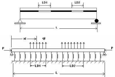
As mentioned earlier in the study, Wang and Chang have developed a buckling analysis method by using spring simulation technique for plates which contain through-the-width delaminations [10]. Since the plates are assumed to be free along their longitudinal edges, they are categorized as beam-plates which encounter cylindrical bending. In their study, the system is modeled as a beam supported on a continuous elastic foundation by using parallel spring distribution (Fig. 1). The stiffness of the springs is assumed constant. It is noted that in order to make the analysis continuous, the spring distribution is used for the delaminated regions as well as for the undelaminated regions. However, in the delaminated regions, some fictitious transverse forces are added at a number of discrete points in order to make the net transverse force at each of these points to vanish.
Figure 1: A continuous model of a delaminated plate under compression with parallel springs.
This modeling technique is also capable of simulating generally elastic supports by including the rotational springs with different spring constants at the loaded ends. The same modeling technique is adopted in the current study, in which the simply supported boundary conditions are assumed at the loaded ends. Effectively, by increasing the stiffness of the springs the boundary conditions at the delamination edges tend to become of clamped nature. However, it is noted that whilst Wang and Chang studies are confined to the problem of either single delamination or multiple delaminations located at the same positions across the thickness, the scope of the current paper is significantly enhanced by extending the application of the spring modeling technique to the problem of laminates containing multiple through-the-width delaminations located at different positions across the thickness.
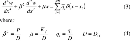
The governing out-of-plane differential equation for a symmetrically laminated composite plate which is under in-plane loadings Nx, Ny, Nxy as well as a transverse load q
(1) q y w N y x w N x w N y w D y x w D y x w D D y x w D x w D y xy x + ∂ ∂ + ∂ ∂ ∂ + ∂ ∂ = ∂ ∂ + ∂ ∂ ∂ + ∂ ∂ ∂ + + ∂ ∂ ∂ + ∂ ∂ 2 2 2 2 2 4 4 22 3 4 26 2 2 4 66 12 3 4 16 4 4 11 2 4 ) 2 ( 2 4
where w is the out-of-plane deflection and Dij coefficients
are the bending stiffness terms for the composite plate. For a specially orthotropic plate subjected to uniaxial in-plane compression Nx, whilst undergoing cylindrical
bending, the governing equation can be simplified as follows: (2) q x w N x w
D x =
∂ ∂ + ∂ ∂ 2 2 4 4 11
The above equation is assumed to be applicable to the analysis of each sublaminate which exists in a beam-plate with multiple delaminations. This means that an individual sublaminate is assumed to be specially orthotropic, and encounter cylindrical bending. For a given sublaminate, the transverse load (q) is the force due to the springs and fictitiously added transverse forces. For a sublaminate, (2) will become [10]:
(3)
(
)
= − = + + ND i i i x x q w dx w d dx w d 1 2 2 2 4 4 δ µ β where: (4) 112 D D
D q q D K D P i i f = = = = µ β
and P is the axial compression force, Kf is the transverse
stiffness of the parallel springs, D is the flexural stiffness of the sublaminate, qi is the fictitious transverse loads
added at the delaminated regions, (x-xi) is the Dirac-delta
function and ND is the number of the discrete points taken in the delaminated regions.
The simply supported boundary conditions at the loaded ends (at x=0 and x=L) are:
(5) 0 , 0 2 2 = = dx w d w
The transverse displacement for the sublaminate with simply supported boundary conditions is represented in the following form:
(6)
( )
L m L x x a W x w m m m m π α = = ∞ =1 0 sinBy substituting (6) in the governing differential equation (3), the Wm coefficient for m ranging from 1 to
: (7) = = n i i m i m
m q x
L L W 1 4 sin 2 1 α λ π where: (8) 2 2 4 4 2 4 L D P D L K K m P P K m E f E m π π λ = = − + =
As mentioned at the beginning of this part, the net traction at each point x=xi in the delamination region is
required to vanish, i.e.,
(9) ∆ + ∆ − = 2
2 ( )
i i i i x x x x f
i K w x dx
q
that may be approximated for a small value of xi by:
(10) i
i f
i K wx x
q = ( )∆
With the assumption of constant xi= x in the
numerical computations and by substituting the Wm given
in (7) in (6) and (10), a system of homogeneous algebraic equations in terms of qi (i=1,2,…,ND) is obtained. This
leads to n equations which can be written in a matrix form:
(11)
[ ]{ }
A X =0The elements of the vector
{ }
X are the transverseloads qi(i=1,2,…,ND), which are yet unknown and the
elements of the matrix A are:
(12) j m i m m m ij j
i x x
x
K L
a α α
λ π δ
π sin sin
1 2 1 2 3 2 , ∞ = ∆ + − =
The non-trivial solution for (11) is obtained by setting the determinant of the matrix A equal to zero. This corresponds to finding the lowest value of buckling load P (i.e. Pcr)
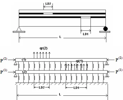
Fig. 2 shows a composite plate containing two through-the-width delaminations in different positions across the thickness. This problem is attempted to be solved by applying the continuous modeling concept of distributed springs, which is depicted in Fig. 2. It is noted that the total load P is composed of two parts; namely P(1)
and P(2), which are the loads applied to the sublaminates (1) and (2) respectively. It is also noted that the following relationship exists among the loads:
(13-a) ) 2 ( ) 1 ( P P
P= +
Figure 2: A continuous model of a delaminated plate under compression with parallel springs containing two through-the-width delaminations
The springs are considered between the sublaminates (1) and (2) as well as between the sublaminate (1) and the base laminate. The governing coupled differential equations are: (14)
(
)
(
)
− − − = + − + − − = + = = ) ( ) ( ) 1 ( ) 2 ( ) 2 ( 1 ) 2 ( 2 ) 2 ( 2 ) 2 ( 4 ) 2 ( 4 ) 2 ( 11 ) 1 ( ) 2 ( ) 2 ( ) 1 ( ) 1 ( 1 ) 1 ( 2 ) 1 ( 2 ) 1 ( 4 ) 1 ( 4 ) 1 ( 11 ) 2 ( ) 1 ( w w K x x q dx w d P dx w d D w w K w K x x q dx w d P dx w d D f ND r r r f f ND i i i δ δwhere the superscripts are related to the sublaminates (1) and (2), and ND(1) and ND(2) are the number of the discrete points taken in the delaminated regions. Boundary conditions at the loaded ends (x=0, x=L) are simply supported: (15) = = = = = = 0 0 0 0 0 0 2 ) 2 ( 2 ) 2 ( 2 ) 1 ( 2 ) 1 ( dx w d w x dx w d w x
Similar to the case of a plate with one through-the-width delamination, in the case of a plate with multiple delaminations, the transverse displacement for each sublaminate can be represented by the following equations: (16) ( ) ( )= = = = ∞ = ∞ = L m L x x W x w L m L x x W x w m m m m m m m m π α α π α α 1 ) 1 ( ) 1 ( 1 ) 2 ( ) 2 ( 0 sin 0 sin
By substituting (16) in the governing differential equations (14) the W(1)m and W
(2)
m coefficient for m
ranging from 1 to are obtained:
(17) + = + = = = ) 2 ( ) 1 ( 1 ) 2 ( 11 ) 2 ( ) 2 ( ) 2 ( 4 ) 2 ( 1 ) 2 ( ) 1 ( 11 ) 2 ( ) 1 ( ) 1 ( 4 ) 1 ( ) / ( sin 2 1 ) / ( sin 2 1 ND r m f r m r m m ND i m f i m i m m w D K x L q L W w D K x L q L W α λ π α λ π where: (18)
(
)
2) 1 ( 11 ) 1 ( 4 ) 1 ( 11 4 ) 2 ( ) 1 ( 4 ) 1 ( m D P D L K K
m f f
m − + + = π λ (19) 2 ) 2 ( 11 ) 2 ( 4 ) 2 ( 11 4 ) 2 ( 4 ) 2 ( m D P D L K m f
m = + −
π λ
In line with the solution procedure adopted earlier in the study for the case of a single delamination, the net traction at each discrete point in the delamination regions is required to vanish, i.e.,
(20) / 2
(1) (1) (1)
/ 2 / 2
(2) (2) (2) (1)
/ 2 ( ) ( ( ) ( )) i i i i r r r r x x
i x x f i
x x
r x x f r r
q K w x dx
q K w x w x dx
+∆ −∆ +∆ −∆ = = −
which may be approximated for a small and constant value of xi= xr= x by:
(21) (1) (1) (1)
(2) (2) (2) (1)
( )
( ( ) ( ))
i f i
r f r r
q K w x x
q K w x w x x
= ∆
= − ∆
Similar to the case of a single delamination, by substituting (17), (18), (19) into (16), and substituting the outcome into (21), a system of homogeneous algebraic equations in terms of qi(1) (i=1,2,…, ND(1)) and qr
(2)
(r=1,2,…, ND(2)) is resulted. The resulting ND(1)+ND(2)
equations can be written in the following matrix form:
(22)
[ ]{ }
A X =0The elements of the vector
{ }
X
are the qi(1) and qr(2)which are unknown, and the elements of the matrix A are dependent to the applied loads P(1) and P(2). The non-trivial solution for (22) is attempted by setting the determinant of the matrix A equal to zero. The resulting equation is solved in conjunction with (13-a), (13-b) and (13-c) to find the lowest value of the buckling load P.
3. FINITE ELEMENT ANALYSIS
The FEM analysis is performed in order to investigate the validation of the results obtained by the method developed in the current study. The FEM buckling analysis is performed employing ANSYS5.4 software, commercially available finite element code. Within ANSYS5.4 software, the buckling analysis is a two-pass analysis. The first pass is a linear static analysis which determines the stresses for a given reference set of loads. The second pass is an eigen-value analysis which provides the results in terms of load factors (eigen-values) and mode shapes (eigen-vectors).
approaches are adopted. In the first approach, which is designated as Beam modeling technique, the model is constructed by using beam elements which are supported on the elastic foundation. It is noted that each beam element has two nodes. In the second approach, which is designated as Shell modeling technique, the beam elements considered in the Beam modeling technique is replaced by 4-noded shell elements which are again supported on the elastic foundation. Finally, in the third approach designated as Solid modeling technique, the whole laminate is modeled by implementing layered 8-node brick elements with 3 degrees of freedom at each node.
It is noted that in all cases of FEM models, the mesh is further refined at the discontinuous delamination front in order to preserve the accuracy of the results.
4. RESULTS ADN DISSCUSION
The material properties of the carbon/epoxy which are used in this study are E11=148000MPa, E22=9650MPa, G12=4550
MPa
and υ12=0.3.
Fig. 3 depicts the convergence investigation for the buckling load of a simply-supported laminate with a central through-the-width delamination. The lay-up sequence of the sublaminate is [0,90,90,0] and the thickness of the sublaminate is 1mm. The length of the plate is L and the delamination length is LD. The buckling loads are non-dimensionalised by the buckling load Pcr,
which corresponds to the converged buckling load of the plate under consideration. The numerical values of the geometrical parameters and material properties are shown in the figure. The parameter m represents the number of terms in the Fourier series which postulates the transverse deflection of the plate. The parameter ND is the number of discrete points in the delaminations regions.It is seen in the figure that for a given number of discrete points, the buckling load is decreased and converged to a certain load by increasing the number of terms in the Fourier series.
0 0.5 1 1.5 2 2.5 3
0 5 10 15 20 25 30
m
P
/P
c
r
Developed Method,ND=50 Developed Method,ND=100 Developed Method,ND=150 Developed Method,ND=200
Figure 3: Convergence study of buckling loads for a laminate with a central delamination (L=0.797m, LD=0.305m, Kf=27E6
N/m3
, D=11.3N-m, Pcr=120.5N)
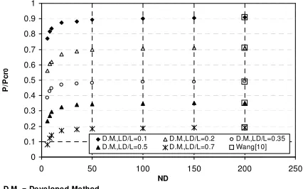
Fig. 4 also shows the convergence study for simply-supported plates with a centrally through-the-width delamination. The lay-up sequence of the sublaminate is [0,90,90,0] and the thickness of the sublaminate is 1mm. In this figure, the variation of the dimensionless buckling loads with the change in the number of discrete points ND
is depicted. The buckling loads are non-dimensionalised by the buckling load Pcr0, which corresponds to the buckling load for a plate without delamination. The numerical values of the geometrical parameters and material properties are shown in the figure. The effects of change in the delamination length LD on the buckling load are also investigated in Fig. 4. The figure shows that for any given delamination length, a converged value of the buckling load can be obtained by using approximately 100 discrete points. It is noted that the number of terms in the Fourier series is assumed to be nine (i.e. m=9). Moreover, a very good agreement is seen to exist between the converged results obtained in the current study and those obtained by Wang and Cheng [10].
D.M. = Developed Method
0 0.1 0.2 0.3 0.4 0.5 0.6 0.7 0.8 0.9 1
0 50 100 150 200 250
ND
P
/P
c
r
0
D.M.,LD/L=0.1 D.M.,LD/L=0.2 D.M.,LD/L=0.35 D.M.,LD/L=0.5 D.M.,LD/L=0.7 Wang[10]
Figure 4: Convergence study of buckling loads for laminates with a central delamination (L=0.797m, Kf=27E4 N/m3, D=11.3
N-m
, Pcr0=86.6N, m=9)
0 0.05 0.1 0.15 0.2 0.25 0.3 0.35 0.4
0 0.1 0.2 0.3 0.4 0.5 0.6 0.7 0.8 0.9 1
LD/L
P
/P
c
r0
FEM-Beam FEM-Shell FEM-Solid
Developed Method, ND=150, m=9
Figure 5: Non-dimensional buckling loads of laminates containing a central delamination (L=0.797m, Kf=27E8 N/m3, D=11.3N-m, P
cr0=4397.3N).
Fig. 6 depicts the variation of the dimensionless buckling loads with the change in the position of a through-the-width delamination along the length of a simply-supported plate. The lay-up sequence of the sublaminate is [0,90,90,0] and the thickness of the sublaminate is 1mm. The buckling loads are non-dimensionalised by the buckling load Pcr0, which corresponds to the buckling load for a plate with a centrally located delamination. The numerical values of the geometrical parameters and material properties are shown in the figure. Two different FEM analyses, namely Shell and Solid, are carried out and their results are presented in the figure. Moreover, the results obtained by Wang and Cheng [10] are also presented. Once again, a very good agreement is seen to exist between the results obtained by the application of the developed technique with those either obtained from FEM analyses or available in [10]. The figure shows that as long as a non-central delamination is located close to the centre, the buckling load of a plate with a non-central delamination is almost equal to that of a plate with a central delamination. However, as the delamination moves near to the ends of the plate, a significant loss in the buckling capacity of the sublaminate occurs. It is noted that the comparable results are obtained by using much less degrees of freedom in the presented method in comparison with the solid finite element analysis. For example, in the case of the plates with single through-the-width delaminations 150 degrees of freedom have been used for the presented method whilst for the same case 8600 degrees of freedom have been used in the solid finite element analysis.
Fig. 7 represents the variation of the dimensionless buckling loads for a plate which contains two through-the-width delaminations at different locations along the length. It is noted that both delaminations are located at the same position across the thickness of the plate.
It is
also noted that whilst the position of one of the delaminations is assumed to remain unchanged and stay at the centre, the effects of change in the position of the other delamination along the length of the plate are
investigated. The lay-up sequence of the sublaminate is [0,90,90,0] and the thickness of the sublaminate is 1mm. The values of the geometrical parameters are shown in the figure. The material properties of the plate and the buckling load Pcr0 are the same as those considered earlier in connection with the plates studied in Fig. 6. The FEM analyses based on Shell modeling technique are also performed to find the buckling loads of plates containing multiple through-the-width delaminations. It is seen that the buckling loads obtained in the present study by the application of the developed spring simulation technique are in good agreement with those available in [10] and with FEM results. It is also seen that when one of the delaminations is fixed at the center of the plate whilst the position of the other delamination is moved towards the ends of the plate, the buckling load for the plate with two delaminations are converged to the buckling load of a plate containing one delamination. In other words, in the case of a plate with two delaminations, the effects of the centrally fixed delamination on the buckling load becomes insignificant as the other delamination moves towards the ends of the plate.
0 0.2 0.4 0.6 0.8 1 1.2
0 0.1 0.2 0.3 0.4 0.5
D0/L
P
/P
c
r0
Developed Method,ND=150,m=9 Wang[10]
FEM-Shell FEM-Solid
Figure 6: Non-dimensional buckling loads of laminates with a single delamination (L=0.797m, LD=0.1L, Kf=27E6 N/m3, D=11.3N-m, Pcr0=446.2N).
0 0.2 0.4 0.6 0.8 1 1.2
0 0.08 0.16 0.24 0.32 0.4 0.48 0.56
Ds/L
P
/P
c
r
0
Multiple delamination, Developed Method, ND=150,m=9 Multiple delamination, Wang[10]
single delamination, Wang[10] Multiple delamination,FEM-Shell
Figure 7: Non-dimensional buckling loads of laminates with two through-the-width delaminations (L=0.797m, LD1=LD2=0.1L,
Fig. 8 shows the variation of the
dimensionless
buckling load of a plate, which contains two through-the-width delaminations located at different position across the thickness of the plate, with changes in the position of the delaminations through the length of the plate It is noted that the delaminations are of the same length, and move together along the length of the plate. The lay-up sequence of the each sublaminates is [0,90,90,0] and the thickness of the each sublaminate is 1mm. It is also noted that the buckling loads are non-dimensionalised by the buckling load Pcr0, which corresponds to the buckling
load for a plate without delamination. The numerical values of the geometrical parameters and material properties are shown in the figure. It may be noted that both sublaminates are identical as far as the geometrical parameters and material properties are concerned. The FEM analyses based on Solid modeling technique are also performed to find the buckling loads of plates. It is seen that the buckling loads obtained in the present study by the application of the developed spring simulation technique are in good agreement with those obtained from FEM. Similar to that experienced earlier in connection with the plates containing a single delamination (see Fig. 6), it is seen in Fig. 8 that as long as the non-central delaminations are located close to the centre, the buckling load of a plate with two non-central delaminations is almost equal to that of a plate with two central delaminations. However, as the delaminations move near to the ends of the plate, a significant loss in the buckling capacity of the plate occurs.
0.0 0.2 0.3 0.5 0.6 0.8 0.9 1.1 1.2
0 0.1 0.2 0.3 0.4 0.5
D0/L
P
/P
c
r0
Developed Method,ND 1=150,ND2=150,m =9 FEM-Solid
Figure 8: Buckling loads of laminates with two through-the-width delaminations (L=0.797m, LD1=LD2=0.1L, K(1)
f=K(2)f =27E6 N/m3, D1=D2=11.3N-m, P
cr0=511.1N).
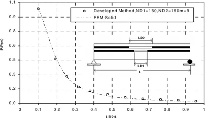
Fig. 9 shows the variation of the buckling load of a plate, which contains two central delaminations at different positions across the thickness, with the change in the length of one of the delaminations, whilst the length
of the other delamination is kept constant (i.e.,
LD1=0.1L). The lay-up sequence of each sublaminates is
[0,90,90,0] and the thickness of each sublaminate is 1mm. The material properties and thickness of the sublaminates, and the buckling load Pcr0 are the same as those
considered earlier in connection with the plates studied in Fig. 8.
0 .0 0 .2 0 .3 0 .5 0 .6 0 .8 0 .9 1 .1
0 0 .1 0 .2 0.3 0 .4 0 .5 0.6 0 .7 0 .8 0 .9 1
L D2/L
P
/P
c
r0
D e ve lo p e d Me th o d ,N D 1 = 1 5 0 ,N D 2 =1 5 0 m =9 FE M-S o li d
Figure 9: Buckling loads of laminates with two central declamations (L=0.797m, LD1=0.1L, K(1)f=K(2)f=27E6N/m3, D1=D2=11.3N-m, Pcr0=511.1N).
It is seen in Fig. 9 that the buckling load of the laminate is significantly diminished by the increase in the length of the delamination. Once again it is seen that the buckling loads obtained in the present study by the application of the developed spring simulation technique are in excellent agreement with those obtained from FEM analysis.
5. CONCLUSION
A continuous method of analysis is developed for determining the buckling loads of plates containing multiple through-the-width delaminations. In the developed method, the springs of constant stiffness are distributed between the delaminated layers. The results obtained have provided confidence in the validity of the formulation of the developed method. It is worth mentioning that in the cases analyzed and discussed in this study the difference between the obtained results by using presented method and finite element analysis is between 0.05% and 4.2%. Moreover, the ability of the developed method to provide valuable insight into the buckling behavior of the delaminated plates has been demonstrated.
6. REFERENCES
[1] H. Chai, C. D. Babcock, and W. G. Knauss, "One dimensional modeling of failure in laminated plates by delamination buckling," International Journal of Solids and Structures, Vol. 17, pp 1069-1083, 1981.
[3] K. N. Shivakumar, and J. D Withcomb, "Buckling of sublaminate in a quasi isotropic composite laminates," Journal of Composite Materials, Vol. 19, pp 2-18, 1985.
[4] J. S. Anastasiadis, and G. J. Simitses, "Spring simulated delamination of axially loaded flat laminates," Composite Structures, Vol. 17, pp 67-85, 1991.
[5] B. D. Davidson, "Delamination buckling: theory and experiment," Journal of Composite Materials, Vol. 25, pp 1351-1378, 1991.
[6] C. H. Piao, "Shear deformation theory of compressive delamination buckling and growth," AIAA Journal, Vol. 29, No. 5, pp 813-819, 1991.
[7] H. Suemasu, "Compressive behavior of fiber reinforced composite plates with a center delamination," Adv. Composite Materials, Vol. 1, No. 1, pp 23-37, 1991.
[8] H. Suemasu, "Effects of multiple delaminations on compressive buckling behaviors of composite panels," Journal of Composite Materials, Vol. 27, No. 12, pp 1172-1192, 1993.
[9] M. Adan, I. Sheinman, and E. Altus, "Buckling of multiply delaminated beams," Journal of Composite Materials, Vol. 28, No. 1, pp 77-90, 1994.
[10] J. T. S. Wang, and S. H. Cheng, "Local buckling of delaminated beams and plates using continuous analysis," Journal of Composite Materials, Vol. 29, No. 10, pp 1374-1402, 1995.
[11] J. T. S. Wang, and J. T. Huang, "Strain energy release rate of delaminated composite plates using continuous analysis," Journal of Composites Engineering, Vol. 7, pp 731-744, 1994. [12] K. W. Shahwan, and A. M. Wass, "A mechanical model for the
buckling of unilaterally constrained rectangular plates," International Journal of Solids and Structures, Vol. 31, No. 1, pp 75-87, 1994.
[13] D. W. Sleight, and J. T. Wang, "Buckling analysis of debonded sandwich panel under compression," NACA Technical Memorandum, 1995.
[14] D. Shu, "Buckling of multiple delaminated beams”, International Journal of Solids and Structures," Vol. 25, No. 13, pp 1451-1465, 1998.
[15] N. G. Andrews, R. Massabo, and B. N. Cox, "Elastic interaction of multiple delaminations in plates subject to cylindrical bending," International Journal of Solids and Structures, Vol. 43, pp 855-886, 2006.
[16] H. R. Ovesy, H. Hosseini-toudeshky, and M. Kharazi, "Buckling analysis of laminates with multiple through-the-width delaminations by using Spring simulated model," in Proc. of III European Conference on Computational Mechanics Solids, Structures and Coupled Problems in Engineering, Lisbon, Portugal, 5-8 June 2006, (Published by Springer – Netherlands).
[17] M. Kharazi, H. R. Ovesy, and S. A. M. GhannadPour, "The buckling analysis of delaminated composite plates including the effects of b bend-twist coupling by using spring simulation technique," in Proc. of the 8th
International Conference on Computational Structures Technology, Gran Canaria, Spain, 12-15 Sep 2006, (Published by Civil-Comp Press – Scotland). [18] M. Kharazi, and H. R. Ovesy, "Postbuckling behavior of
composite plates with trough-the-width delaminations," in Proc. of the Thin-Walled Structure Conference,, University of Strathclyde, Glasgow, UK, 26-27 June 2007.
[19] J. M. Whitney, Structural analysis of laminated anisotropic plates, Technomic Publishing Company. Ink 1987.