Paper received: 28.2.2008 Paper accepted: 15.5.2008
Enabling Interactive Augmented Prototyping by a Portable
Hardware and a Plug-In-Based Software Architecture
Jouke Verlinden* - Imre Horvath
Delft University o f Technology, Faculty o f Industrial Design Engineering, The Netherlands
Interactive Augmented Prototyping (IAP) combines digital and physical modeling means to support design processes. Although pilot implementations indicate a possible added value, practical use is hindered by the fa ct that no off-the-shelf solution exists.. Based on empirical studies and assessment o f emerging technologies, this article introduces a projector-based IAP hardware platform called I/O Pad. Furthermore, a flexible software architecture is presented that supports a multitude o f input devices and usage scenarios. In this architecture, an existing 3D CAD system is extended by a collection o f plug-ins. The plug-ins are responsible fo r managing specific elements o f the interactive augmented prototyping process. A first implementation has
been developed, using a small projector and a handheld PC, which proves the wireless versatility o f the hardware platform. The proposed software architecture allows the designer to work in a familiar modeling environment yet includes powerful conceptsfrom tangible user interfaces to support several types o f interaction with physical components.
© 2008 Journal o f M echanical Engineering. A ll rights reserved.
Keywords: augmented reality, interactive prototyping, software architecture, CAD
1 INTRODUCTION
In su p p o rtin g d esig n and p ro to ty p in g activities, Augmented Reality technology provides an appealing solution that combines physical and virtual reality. This combination m ight eliminate some o f the problems associated to an entirely virtual or physical application. Several researchers have explored this concept o f Interactive Augm ented Prototyping, e.g. [2], [7], [14] and [23]. In an earlier publication [
22
] existing applications and enabling te c h n o lo g ie s w ere su rv ey ed . T he p re se n te d augm ented prototyping system s show cased the power o f tangible computing as natural, embodied interaction. Several augmentation techniques could be found in Milgram and Koshino’s reality-virtuality continuum [13] to mix physical prototypes with digital imagery.A t p re s e n t, the re q u ire d te c h n o lo g ie s constitute a wide palette o f input, processing, and output principles; devices and algorithms that are unknown for traditional CAD developers or users. F urtherm ore, these solutions ty p ically rely on custom -coded applications that are incompatible with existing CAD systems (both user interface and m o d e lin g c a p a b ilitie s d iffe r). W ith som e
exceptions, typical Augmented Reality systems are bulky and prone to noise.
This article presents a system to support IAP, based on three extensive case studies in which design processes were empirically followed. The proposed solution comprises both hardware and softw are and is targ eted to enrich the design process.
1.1 Empirical Findings
In order to obtain insight in the possibilities and limitations o f current prototyping practice in industrial design, three design projects in different sub domains have been monitored: the design o f a tractor, a handheld oscilloscope, and the interior for a m useum [21]. These represent a range of industrial design engineering domains, which were considered to be susceptible to support by IAP (automotive, information appliances, and furniture design). Our objective was to produce a deep and accurate account o f prototyping and m odeling a c tiv itie s , w ith a p rim a ry fo cu s on p ro d u ct representation and design reviews.
The field studies were used as a starting point to compile characteristics and specific events
that influenced the design processes, which we g ro u p e d in fo u r d iffe re n t p e rs p e c tiv e s : fu n ctio n alist, interpretive, em ancipatory, and postmodern. The four perspectives originate from organizational sciences and relate to different o b je c tiv e s th a t d e sig n e rs m ig h t h av e fo r a p a r tic u la r re p re s e n ta tio n , re s p e c tiv e ly : i) efficiency, ii) increasing shared understanding, iii) influencing decision making, and iv) creativity [24]. This body o f findings was then used to id en tify sp ecific IAP functions, grouped per scenario as discussed in the following section. Furthermore, the present physical prototypes have b e e n a n a ly z e d to id e n tify n o n -fu n c tio n a l re q u ire m e n ts . Som e o f th e re q u ire m e n ts pertaining to hard- and software will be reiterated and expanded in sections 2 and 3.
1.2 Scenarios
Based on the three case studies and the four perspectives, a num ber o f IAP functions were identified. Main categorization aspect is a particular usage scenario, which differs among the domains and intended prototyping goals:
• User studies - evaluating intermediate designs by using the prototype as a stim ulus. The prototype also acts as an excuse to study the u se r in its natural h ab itat and to provoke comments on product specifications.
• Exploration - probing various aspects o f the design to diverge or understand underlying re la tio n sh ip s; e ffe ctiv ely creating design proposals, som etim es in com bination w ith extensive simulation means.
• D esign review - making' design decisions, discussing design alternatives and considering the strengths and weaknesses as perceived by different stakeholders.
• Presentations to customers, higher management - inspire and po ssib ly overw helm distant stakeholders or public w ith (interm ediate) results and possibly show user studies.
At present, the collection includes over 29 functions, sum m arized in the appendix o f this article. However, in developing IAP support, we do not strive to deliver a Swiss army knife that covers all o f these functions in a single module. Instead, smaller subsets o f functions can be linked to the situation at hand and this will determine what IA P h ard - and so ftw are co n fig u ra tio n m ost
1 www.opencascade.org
appropriate; this customization will be discussed in section 4.3.
1.3 Related Work
In earlier publications, we have selected projector-based augmented reality systems as the most likely candidate to support design [21]. The principle of projector-based augmented reality is treated in Bimber and Raskar [3]; it provides com putational solutions to the challenges o f projector-based Augmented Reality. Issues like registration o f virtual and physical coordinate systems, calibration of colors and the simultaneous use o f multiple projectors. However, the solutions are fragmented and not implemented in a single platform.
Conversely, a number of Augmented Reality software architectures have emerged, for example Studierstube [17], Avalon [1], and Avocado [18]. These deal with position tracking, virtual camera updating and provide hooks to script interactivity. All existing software platforms focus on video m ixing or see-through system s, and require adaptation to support projectors. Furthermore, the integration with modeling and simulation has not been addressed to a generic level. The main focus is to in support OpenGL based rendering libraries or X3D/VRML-based scene graph management. Story- based AR systems like DART [12], Geist [10], AMIRE [28] and the APRIL language [11] focus on playing narrative experiences in AR systems. All these solutions do not directly fit high-level CAD operations and m odel conv ersio n s, w hile engineering simulations have to be hard-coded which makes employment o f for example injection flow-molding, finite elements analysis or fluid dynamics simulations difficult to implement and adapt. Similarly, middleware to run shared AR like Muddleware [26] focus on multi-user game playing and level o f detail management and do not support interactive visualization and adaptation o f objects.
2 IAP HARDWARE
To establish augmented reality for design, a growing selection o f output, input, and physical prototyping has to be considered. A treatise o f these enabling hardware technologies was published in [
21
]; as output means, our first preference is the projector-based display. On input and physical m o d el m a k in g , a w id e v a rie ty o f o p tio n s is available, none o f w hich pro v id ed a com plete solution. Based on the situation at hand, a final selection will have to be made.2.1 Hardware Requirements
In considering current design practice and fu tu re s u p p o rt s c e n a rio s , w e id e n tifie d the following requirements regarding IAP hardware: • Mobility: design reviews often take place at the
location o f client or at other stakeholders; the IAP apparatus should fit in two reasonably sized suitcases and should w ithstand unsupervised transport (by air, in trunk o f a car).
• In s ta llm e n t: d u rin g th e e x e c u tio n o f the scenarios presented at Section 1.2, installment o f time and effort should be kept at a minimum (max 15 minutes, w ith self-starting facilities). I f calibration is required, the system should p ro v id e s te p -b y -s te p g u id a n c e . We acknowledge the constraint uttered by [26] that such devices should be self-contained units with no loose parts, w hich should auto-start if a failure occurs.
• F ix a tio n : p o s itio n and o rie n ta tio n o f the p ro je c to r system s should be fixed w ithout creating hazardous or erroneous situations. In the case that a projector is a hand-held system, it should have a facility to stay in a particular posture while the user can release it.
• Portability: during use, the projector systems could be m oved and this should be doable by one person. To enable this, the amount o f cables should be kept at a minimum.
• Time performance: as the IAP concerns both m odel in sp ectio n as m odel ad ap tatio n and simulation, the update frequency is important to keep an interactive 3D experience. The complete system must run at least at 10 Hz, with little lag tim e as possible
• Accuracy performance: constrains on tracking accuracy and projector resolution are situation
dependent. This also depends on the scale of the physical model and the level o f detail of the projected information. This issue requires revisiting during evaluation.
• Environment interaction: IAP systems should not adversely influence general environmental conditions, in particular regarding noise and lig h tin g condition. A s p ro jecto rs typically contain fans, noise should be minimized in order to su p p o rt re g u la r co n v ersatio n s (m ax 30 decibels, the level o f whispering). Furthermore, IAP systems might require a dimmed room, but it should still be possible to see and interact w ith o th e r p e rso n s and o b je c ts in the environment. A minimum level o f 200 LUX is allowed (a dimmed training room).
• Projector performance: a lot o f variation exists in projector specifications, like resolution, zoom ra n g e , fie ld o f d e p th an d lig h t in te n sity However, little can be constrained regarding these ch aracteristics, as the application in depends strongly on for example distance to the object.
2.2 System Framework: the I/O Pad
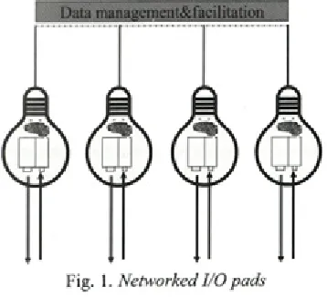
As a fundament for the hardware platform, we would like to adopt the paradigm o f the I/O bulb as presented by Underkoffler and Ishii [19]. The I/O bulb (Input-Output bulb) views the input (camera or other sensors) and output (projector) as one single unit. This bulb can be switched on and o ff at will, can be configured in groups and so on. F o r ex am ple, each I/O bulb could perform a particular task: 3D modeling, simulation analysis o r a n n o ta tio n m a n a g e m e n t. In th is fash io n , dedicated projector modules can be viewed as a
physically addressable (i.e. tangible) component. A s d e m o n stra te d by the so -c a lle d p rocam s
com m unity
2
(projector-cam era system s), manyalgorithms and applications have evolved that can be employed in this setup including calibration of colors temperature, 3D scanning, and visual echo canceling.
We ex te n d the I/O bu lb co n cep t, by including processing power and a touch screen interface, the result o f which we would like to label as I/O Pad. As its name suggests, it is supposed to fit w ithin the series o f tangible user interfaces devised to blend physical and virtual realms like I/ O bulb and I/O brush [16]. The I/O Pad is a self- sufficient, untethered device (if battery operated). Collaboration o f multiple pads is facilitated through wired or wireless network connections. In essence, our concept overlaps with iLamps [15]; both add handheld, geometrically aware projection and allow ad-hoc clustered projections. However, the I/O Pad differs in three ways: i) each I/O Pad contains a touch screen to interactively capture and display sketches and gestures from designers, ii) each pad is equipped with recording devices (webcam) to p ick up discussions and u sab ility assessm ent sessions, and iii) the I/O Pad network architecture encompasses a distributed structure to facilitate data sharing, dialogue management and in particular session recording, As shown in Figure 1, different
Table 1 .Characteristics o f two Smart I/O Pads
H a n d h e l d I /O P a d
L a r g e I / O P a d
Projector LED-based, battery operated
Silent standard video projector. Projector power 30 Lumen 3000 Lumen Projected
resolution
800x600 pixels 1280x768 pixels Working distance
from object
10-50 cm 100-300 cm Processing unit UMPC Tablet PC Touchscreen
diameter
5-7 Inches 12-15 Inches 3D tracking Marker-based
(ARToolkit)
Active/passive infrared tracking (motion capture system, camera includes infrared canon)
Estimate total weight
1 kg 2.5-3 kg
instantiations o f the I/O Pads m ight be used concurrently. To support particular activities, some pads m ight be sw itched on or o ff or m oved according to the user’s whishes.
I/O Pads can be small and portable, or they carry increased projection and computing power. Two extreme versions can be conceptualized, as specified in Table 1. For the handheld system, a sm all, LE D -based p ro jecto r seem s the m ost appropriate; these can run on batteries and are almost silent. As a processing unit, an Ultra-Mobile PC (UMPC) is a good candidate; it contains a touch screen and in fact is a miniaturized PC that runs standard windows or Linux software. Due to the lack o f computing power, a lightweight 3D tracking system should be selected, for example ARToolkit. This is an open source library for optical 3D tracking and tag identification that employs flat rectangular markers [9]; our field tests suggest it w ill perform well on the UM PC platform (approximately 20 Hz, 640x480 camera resolution).
The larger I/O Pad is equipped with more powerful constituents, to offer improved projection, p ro c e ssin g , and 3D track in g . R ecent video projectors offer XGA or higher resolutions and produce over 3000 Lumen. As processing and interaction unit, we propose the employment o f a high-end Tablet-PC with a touch screen option. Such Tablets harbor both active and passive touch technologies and can be operated by fingers and special pens. In the latter case, the tablet is pressure sensitive, which supports the natural expressiveness o f designer’s sketching abilities. To support 3D tracking and user events, this system can be equipped w ith an infrared camera and infrared lamp, as being found in typical motion capture system s like M otion A nalysis and Vicon. By deploying retro-reflective passive m arkers in combination with active, LED-based tags, both fine-grained 3D com ponent tracking and user interaction w ith physical com ponents (by for example phidgets) will be supported. This I/O pad is m eant to offer global lighting o f a design/ environment, from a larger distance. Due to its weight, proper fixture like a professional tripod is essential.
2.3 I/O Pad Implementation
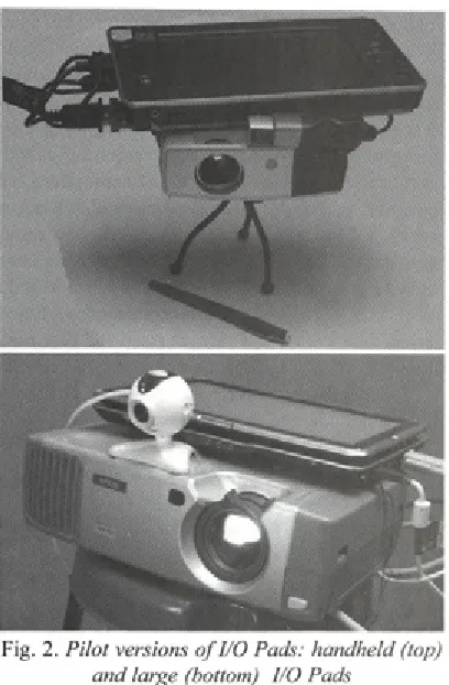
B ased on the h ard w are sp e c ific a tio n s d e sc rib e d above, tw o I/O Pads have been
Fig. 2. Pilot versions o f I/O Pads: handheld (top) and large (bottom) I/O Pads
developed, as depicted in Figure 2. The smallest version contains a L E D -B ased p ro jecto r from Toshiba (FF-1), which weights 750 grams including battery. This projector is connected to an Asus R2H UMPC (900 MHz ULV Celeron processor, 500 MB RAM), which has a 7-inch passive touch screen. A Microsoft NX-6000 web camera delivers up to 2 Mega pixel resolution video images. This package weights approximately 1.5 kilograms.
The larger I/O Pad is based on a standard video projector (Epson EM P-811) that has 2000 lumen and is capable to project at XGA resolution ( 1024x768 pixels). A Tablet PC delivers processing and a passive touch screen (HP TX 1000, AMD dual-core TL50 processor, 1GB RAM, 12.1-inch screen). For Infrared motion capturing the system currently em ploys a Wii rem ote controller (also know n as W iiM ote), w hich is able to track 4 Infrared light sources simultaneously at a resolution o f 1024x768 pixels at 100 Hz. This W iiMote game controller is connected w irelessly to the I/O pad by B luetooth. A converted p en co n tain in g an infrared LED at its tip, plus a battery, and a switch serves as lightpen w hich can be tracked by the WiiMote in two dimensions; contact o f the pen tip
Fig. 3. Workflow o f the WARP system
with the object surface can be reconstructed to a 3D point as the physical surfaces are known, given the exact location and orientation o f the controller. This complete bundle weighs approximately 2.5 kg and requires a professional tripod to aim toward the area o f interest.
T he u se r in te ra c tio n is p e rfo rm e d by operating the touch screens o f the I/O pad, drawing on physical objects surface with the light pen, or moving the model and I/O Pad.
3 IAP SOFTWARE
3.1 IAP Functional Requirements
In devising a software architecture for IAP, the following requirements and were identified: • Operation o f IAP should be compatible with
the user interface and conceptual modeling/ simulation the designer is familiar with. • A wide range o f options to calibrate the I/O pads
w ill be offered (coordinate system s, color, optical distortions).
• The architecture should be open for (future) 3D tracking and event sensing methods.
• The system should auto-start and should offer a number o f preset configurations that fit the scenarios.
• The IAP can relate various physical components to virtual counterparts. The user should be able to attach and detach these in an easy fashion. • IA P w ill also reco g n ize c e rtain physical
behavior as actions (gestures, button presses etc .), w hich can be conn ected to various functions.
• The architecture will support recording all input events and the corresponding 3D m odels. Different levels o f granularity might be selected to optimize recording performance (time, level o f detail, channels).
3.2 WARP 2.0 Architecture
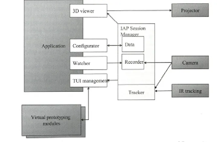
The resulting WARP 2.0 architecture is shown in Figure 4. In the center, the IAP Session M anager is shown. It is responsible for setting up sessions at one or more I/O Pad. This includes model sharing, session recording, and configuration management. As stated in the final requirement, the recording function will combine the modeling history with discussion by recording video and audio as well.
On the right, the set o f input and output devices are shown. Processing o f input signals and 3D tra c k in g is p erfo rm ed by the a T rack er subsystem, which supports an arbitrary number o f commercial and research position sensing devices It is based on (networked) data streams. The data flow based paradigm also enables easy recording o f movement and configurations by storing the streams to persistent memory.
Key ingredient in the IAP architecture is a third-party 3D m odeler or sim ulation package, d ep icted on the left. Instead o f creatin g our
proprietary visualization solution, we w ant to exploit the fact that most designers already have some type of 3D modeling package like Catia, Solidworks or Rhinoceros. M ost o f these are capable render the virtual components in real-time, adjusted for the projector by means o f configuring and maintaining a virtual camera. Furthermore, m ost m odeling packages can be extended by scripting, macros or other automation mechanisms (like ActiveX). For supporting IAP, we have defined four plug-ins that need to be implemented for a particular package: i) Configurator, ii) 3D Viewer, iii) TUI Management, and iv) Watcher. The responsibilities of these are discussed below.
The Configurator plug-in can be viewed as the local liaison of the IAP session m anager- it is responsible for the local setup and execution of other plug-ins, loading/saving models and sharing this with other IAP instances. Furthermore, it offers an auto-start function and a GUI to arrange the IAP in line with the defined application scenarios and the related functions.
The 3D Viewer is responsible to define and update a virtual camera that copies the internal and external param eters o f the attached projector. Internal parameters include field o f view, aspect ratio and projection center; external parameters correspond to translation/rotation of the projector and the scale o f the v irtu a l and re al-w o rld coordinate systems. In term s o f 3D com puter graphics concepts, these are being specified in two transformation matrices: a projection and model matrix [5]. In some cases, these transforms need to be mapped to different units for the CAD package (e.g. CATIA requires focal point instead o f field o f view). When the projector is moved, the virtual cam era w ill to u pdate the m odel tran sfo rm accordingly, based on the input from the IAP session manager. Ideally, the 3D viewer plug in should sense alterations in projector zoom (focal point) and adjust the projection matrix accordingly. Furthermore, the 3D Viewer module is responsible for determining the appropriate field-of-depth and should be capable to adjust the focus o f the projector when required (based on distance between the projector and objects in virtual space).
corresponding virtual components in the modeling or s im u la tio n p a c k a g e . T h is m ig h t e ffe c t in showing/hiding and translating/rotating objects but also steering additional virtual simulation modules (like physics behavior or screen navigation).
The W atch er p lu g -in is re sp o n sib le to support the recording functions, which can be either saved to file or streamed to a centralized session recorder through a network connection. This plug in offers a num ber o f services, including capturing either screenshots, full 3D m odels per stage, or hybrid version o f both based the m odeling events the hybrid option could for example encompass capturing full 3D m odels after alterations o f the m odel, and screenshots during m odel view ing. Furthermore, the update frequency can be set in time or event-based triggers.
Specific interfaces are being determined at this moment. Storage o f data at the IAP Session M anager will based on tuplespaces (also known as a blackboard). This type o f associative memory is highly flexible and supports various mechanisms to share data w ith clients. In particular, the IAP Session M anager uses a publish-and-subscribe protocol in order to propagate events and data streams to those modules that have shown interest. Furthermore, the IAP Session M anager will offer a calibration routine to determine the projection matrix and to determine the (fixed) transformation between 3D tracking and projector positions.
3.3 Plug-in Factory Concept
Although the plug-in architecture offers a lot o f flexibility, it yields challenges tow ards implementation and maintenance o f these plug-ins First, all m odeling applications have their own au to m atio n so lu tio n w hich req u ires different (dialects of) scripting languages; for example Visual Basic for Applications versus C++. Second, each application offers a different set o f operations and data structures, which evolve at each - typically an n u al - u p d ate. C o n fig u ra tio n and version management needs to be addressed in the WARP architecture.
A solution to this problem can be found at the Abstract Factory design pattern [
6
], as depictedin F ig u re 5 fo r th e 3 D v i e w e r and
C o n f i g u r a t o r classes. Abstract classes for each plug-in type define its public interface and contain the basic functions which can be shared among instantiations; for each dialect, the plug-ins are subclassed to adapt for the particular version for example 3 D v i e w e r _ S o l i d w o r k s . Second, a Factory class for each o f the configurations is
d e fin e d , b a se d on the
A b s t r a c t P l u g i n F a c t o r y class. These factory classes are responsible to instantiate the actual plug-ins by means o f C r e a t e ( ) function calls. These instantiation calls will use the publicly available GNU make application
3
to support fileFig. 4. WARP 2.0 Software Architecture fo r Interactive Augmented Prototyping
Fig. 5. UML diagram o f Plug-in factories (illustrated are only ÌDviewer and Configurator plugins)
deployment, shell scripting and compilation/linking in different languages.
From personal experience, we found several ways to hide and show components in Catia; the most straightforward implementation worked, but
resulted in poor perform ance (consum ing
200
milliseconds for one cycle and extensive flashing o f com ponent wireframes). A fter putting some efforts in optimizing this operation, we switched to a less elegant but better working strategy by simply translating objects outside/inside camera reach. S electing and im plem enting strategies requires tuning and such principal solutions should be encapsulated in the Factory classes, in order to share these basic functions among all plug-ins for that particular dialect.
3.4 Deployment and Calibration
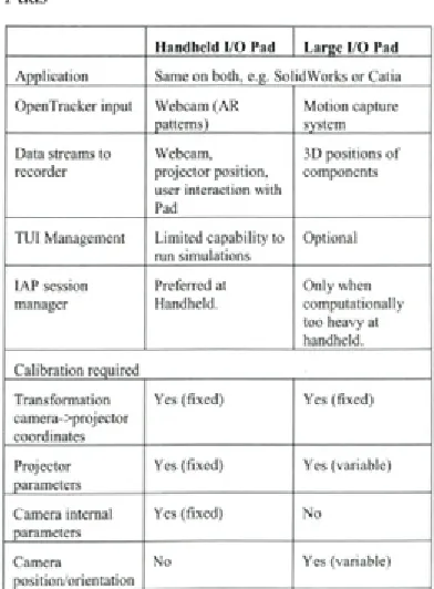
In the case o f using a single I/O Pad, all processes outlined before can run on the same m achine. In order to enable concurrent use o f multiple I/O Pads, a networked system layout is necessary. An overview o f a typical setup is shown in Table 2. As a main communications solution, we have selected OpenSound Control protocol [27], which is currently supported by emerging Tangible U ser Interface APIs. For each projector unit, a
single application instance should run w ith its corresponding plug-ins. The same holds true for the Tracker stack, although these can be combined
Table 2. Software deployment if using Smart I/O Pads
H a n d h e ld I/ O Pad L a rg e I/ O Pad A p p lic a tio n Same on both, e.g. S o lid W o rks o r Catia O penTracker inp u t W ebcam (A R
patterns)
M o tio n capture system Data streams to
recorder
W ebcam, p ro je cto r p osition, user interaction w ith Pad
3D positions o f com ponents
T U I M anagem ent L im ite d c a p a b ility to run sim ula tion s
O ptional
IA P session manager
Preferred at Handheld.
O n ly w hen c o m pu tatio n ally too heavy at handheld. C a lib ra tio n required
Tra n sfo rm atio n cam era->projector coordinates
Yes (fix e d ) Yes (fix e d )
P rojector parameters
Yes (fix e d ) Yes (variable)
Cam era internal parameters
Yes (fix e d ) N o
Camera positio n /o rie n ta tio n
through the data flow definitions. It seems logical to employ a networked file system on all I/O Pad systems, which is hosted by the same machine that runs the IAP Session M anager (o f w hich only one instance should persist). This can be one o f the I/O Pads or a separate server. Another dependency at th is p o in t is th e fa c t th a t m u ltip le p h y sic a l com ponent and event tracking is only supported by the larger I/O Pad, trough the motion capture equipment. Tracking such cues needs at least 2 IR cameras o f w hich one is integrated in the large pad.
Calibration for the I/O pads deals w ith a n u m b e r o f e le m e n ts , m o st n o ta b ly , th e transformation between camera and projector world co o rd in a te sy stem s, d efin ed by the p ro je c to r internal param eters (field o f view, center position), the cam era internal param eters, and the vector (translation/angle) between the two components As both types o f I/O Pads are equipped w ith different hardware, both require separate sorts o f calibration, as summarized in the lower part o f Table 2. The h a n d h e ld u n it ty p ic a lly re q u ire s o n e sin g le calibration step, which can happen after assembly o f the unit. The large I/O pad, however, requires calib ratio n before each installatio n due to the registration o f the IR cameras o f the motion capture system and fluctuations in both projector focal distance (zoom) and color temperature.
4 FIRST APPLICATION AND DISCUSSION
4.1 Application and Findings
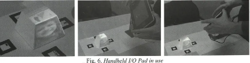
The I/O Pad configurations specified in Section 2.3 were constructed, w ith a specific focus on the handheld system. A n im pression o f this system in use is given in Figure
6
. Four standard ARToolkit markers were placed around a simple object (a cup resembling a pyram id with its top cut off). The geom etry w as m odeled in C atia and decorated by texture maps. The only interactionsupported application was to combine the digital and physical models. At present, the fundaments o f the WARP 2.0 software architecture have been developed, much effort was necessary to devise and im plem ent calibration routines. The calibration procedure was developed and tuned for the simple o bject- the projection (u,v coordinates) o f each of the
8
vertices (x,y,z coordinates) has to be indicated at th e to u c h sc re e n , th e c a m e ra c a lib ra tio n algorithm specified in Faugeras [4, Chapter 1] is used to compute the projection matrix.In this simple application, the computing power o f the small PC was sufficient. Although it is a bit bulky and heavy to lift for longer periods of time, the system was easy to transport and to move while running the system.
In the em pirical case studies, different ap p licatio n s w ere used: CATIA (autom otive), V e c to rw o rk s (in te rio r), an d U n ig ra p h ic s (in fo rm a tio n a p p lia n c e s ). F o r re a so n s o f a v a ila b ility , the m in im al c o llectio n o f target applications for WARP 2.0 has been set to CATIA and Solidworks. Although this is less compatible w ith the interior design domain, these still offer similar m odeling functions while they are based on c o m p le te ly d iffe re n t re p re s e n ta tio n and automation mechanisms.
4.2 Discussion
Software-related issues
W h en m u ltip le I/O P ad s are u sed sim u ltan eo u sly , sy n ch ro n izatio n b etw een the running CAD or simulation packages is necessary. This can be solved in several ways, for example by application sharing (i.e. running the same synchronized instance on all pads), by m odel sharing among different applications (for example on e p a d d e d ic a te d to m o d e lin g and one to sim ulation) or by hosting diverse models o f the same product. More investigations are necessary
to determine which option is the most appropriate. In order to record sessions, the required bandwidth to capture all video and application states can be large. As with traditional capturing systems, a tradeoff has to be made between quality and size/ bandwidth; this is even more in the case o f using m ultiple I/O Pads concurrently. One probable option is to store data locally in real-time and to upload/share this after use.
Projector-related issues
In terms o f luminosity, the projector is useful when it produces 50 to 100% more light at the surface than its environment4; this would equal 300 Lux at the given surface light o f 200 Lux as presented in Section 2.1. Here, we have to take into account that the reflectance o f the (white) object is approximately 80%.
The small projector (Toshiba FF-1) has a m easured pow er o f 16 Lum en5; as Lux equals Lumen per square meter, the conversion has to take into account the maximum envelope o f projection at a certain distance from the object. For the furthest distance o f 40 cm, the projected area is 23.1 by 17.3 ce n tim e te rs or 0.04 m 2; th is re su lts in approximately 400 Lux light energy at the object’s surface, or 320 Lux when corrected for reflectance; this is sufficient. In the case o f the minimal distance o f 20 cm., the area was 12 x 9 cm (0.01 m2), which results in 1185 Lux adjusted for 80% reflectance. In the case o f the larger projector (Epson EMP 811, 2000 Lumen), in the wide-angle setting on a 1- m eter distance, the projected area is 67 x 50 centimeters (0.33 m2); this yields approximately 4800 Lux corrected for reflection. In the furthest specified distance o f 3 meters, the area is 1.99 x 1.47 meters (2.93 m2), resulting in 547 Lux. This means that effectively in all cases the projector brightness is sufficient.
Field o f depth - in experimental studies, we found little issues in using a single, fixed focus on the large projector in the range specified (1-3 meters). For the small projector, the focus remained acceptable in the following ranges: I) between 20 and 30 cm, ii) between 30-50 cm. Its focus ring is not easy to operate, at least not when the projector is assem bled in the I/O pad. Instead, we could imagine a manual o f automatic switch between these two ranges. The autom atic option seems viable, as the distance between projector and object is constantly measured._______________________
4 http://www.dvmg.com.au/iti-fl .html
5 http://www.pcmag.eom/article2/0,2704,2099318,00.asp
Enabling Interactive Augmented Prototyping by a Poi
Noise - for cooling purposes, projectors are equipped with a fan that generates noise. For the small projector this is negligible, but for the larger this is an issue. New “whisper” video projectors are currently being marketed which have better characteristics, but are still not completely silent (yielding approx 28 Decibels).
4.3 Customization of Functions
As m entioned in section 1.1, the basis interpreting the case studies was the framework of Critical Systems Thinking [
8
], Its philosophy of Total Systems Intervention (TSI) will be used in customizing the IAP system towards a particular design situation. TSI has three phases: creativity, choice, and implementation. The creativity phase focuses on selecting a number o f perspectives to assess the situation and to identify concerns and problems. During the second phase, a suitable intervention methodology is selected to deal with the problem at hand, originally based on the collection of methods o f organizational sciences (covering functionalist, interpretive, emancipatory, and postmodern theories); the selected intervention is then implemented in the subsequent phase.In a similar fashion, the use of IAP should be preceded by a similar assessment and selection. The scenarios of IAP have been characterized to cover one or more o f the four theories mentioned above, an overview is given in the Appendix. This ensures coverage o f a number o f concerns and issues during design when either product shape or product behavior plays a role. The application o f TSI in selecting IAP functions can be shaped in several ways, for example as a wizard dialogue, as a flowchart or map or encapsulated in templates.
5 CONCLUSION
A lth o u g h the co n cep t o f in te ra c tiv e augmented prototyping allows possible benefits to design processes, there is a large threshold in employing this technique. In this paper, we have proposed a combination o f hardware and software solutions. Based on empirical findings from three different design processes, functional requirements and usage scenarios were specified.
rep resen ts a fu lly equipped IA P system . Two versions were presented, a larger, more powerful and a smaller, more mobile I/O Pad. M ultiple I/O P ad s can be u s e d c o n c u rre n tly . A n in itia l implementation has been developed, using a LED- based projector and a UMPC. The first application o f the I/O Pad proves the wireless versatility o f the hardware platform.
The software architecture called WARP 2.0 was proposed based on a plug-in architecture to em pow er existing 3D m odeling and sim ulation applications and thus be compatible with existing design practice. The architecture was designed to connect several 3D tracking and sensor devices through a centralized IAP session m anager to an arb itrary n u m b er o f I/O Pads. T he proposed software architecture allows the designer to work in a fam iliar m odeling environm ent yet includes powerful concepts from tangible user interfaces to support several types o f interaction w ith physical com ponents. S econdly, the ap p licatio n o f the A b s tra c t F a c to ry d e sig n p a tte r n s o lv e s th e configuration and version m anagement o f the plug ins.
Technical issues involve application sharing and projector characteristics. As developm ent is still early, it has to be determined to what degree the usability o f the system and the application IAP influences the design process at hand. The resulting I/O P a d s w ill b e te s te d in a s e rie s o f fie ld experim ents, in varying dom ains o f industrial design.
6
REFERENCES[1] Becker, M., Bleser, G., Pagani, A., Strieker, D., W uest H. An architecture for prototyping a n d a p p lic a tio n d e v e lo p m e n t o f v is u a l tracking systems. Int. Conf. on 3DTV, 2007. [2] Bimber, O., Stork, A., Branco, P. Projection-
based augmented engineering. Proceedings o f
International Conference on Human-Computer Interaction (HCI’2001), vol. 1, p. 787-791. [3] Bim ber, O., Raskar, R. Spatial augm ented
reality: merging real and virtual worlds. A. K. Peters, Ltd., 2005.
[4] Faugeras, O. T hree-dim ensional com puter vision: a geometric viewpoint. MIT press, 1993. [5] Foley, J., van Dam, A., Feiner, S., Hughes, J.
Computer graphics: principles and practice.
2nd Ed. inC . Reading: Addison-Wesley, 1995.
[
6
] Gamma, E., Helm, R. Johnson, R., Vlissides, J. D esign p attern s, elem en ts o f reusable object-oriented software. Reading: Addison- Wesley, 1995.[7] G rasset, R., B oissieux, L., G ascuel, J.-D., Schmalsteig, D. Interactive mediated reality.
Proceedings o f AUIC2005, 2005, p. 21-29. [
8
] Ja c k so n , M. S y ste m s a p p ro a c h e s tom anagem ent. N ew York: K luw er/Plenum , 2000, ISBN 0306465000.
[9] Kato, H., Billinghurst, M. Marker tracking and HMD calibration for a video-based augmented
reality conferencing system. Proceedings o f
International Workshop on Augmented Reality (IWAR 99), 1999, p. 85-94.
[10] K retschm er, U ., C oors, V., Spierling, U., Grasbon, D., Schneider, K., Rojas, I., Malaka, R. Meeting the spirit o f history. Proceedings Conference on Virtual Reality, Archeology, and Cultural Heritage VAST ’01,2001, p. 141-152. [11] Ledermann, E , Barakonyi, I., Schmalstieg, D.
Abstraction and implementation strategies fo r augm ented reality authoring. E m erging T e c h n o lo g ie s o f A u g m e n te d R eality :
In te rfa c e s an d D esig n , H aller,
Billinghurst&Thomas (eds), 2006, p. 138-159. [12] MacIntyre, B., Gandy, M., Dow, S., Bolter, J.
D. DART: a to o lk it fo r ra p id d e sig n exploration o f augmented reality experiences.
Proceedings ofU IST ’04, 2004, p. 197-206. [13] Milgram, P., Kishino, F. A Taxonomy o f mixed
re a lity v isu a l d isp la y s. IEC E Trans, on Information and Systems (Special Issue on Networked Reality), vol. E77-D, 1994, no. 12, p. 1321 -1329.
[14] Nam, T-J, Lee, W. Integrating hardware and software: augmented reality based prototyping method for digital products. Proceedings o f C H I’03, 2003, p. 956-957.
[15] R ask ar, R ., v an B aar, J., B eard sley , P., Willwacher, T., Rao, S., Forlines, C. iLamps: g e o m etrically aw are and selfco n fig u rin g
projectors. ACM Trans. Graph. (SIGGRAPH)
22(3), 2003, p. 8 0 9 - 818.
[16] Ryokai, K., M arti, S., Ishii, H. I/O brush: d ra w in g w ith e v e ry d a y o b je c ts as ink.
Proceedings o f Conference on Human Factors in Computing Systems (CHI ’04), 2004, p. 303-310.
M . P u rg a th o fe r, W. T he stu d ie rstu b e a u g m en ted re a lity p ro je c t. Presence -Teleoperators and Virtual Environments, voi. 11(1), 2002, p.33-54.
[18] Tamberend, H. Avocado: a distributed virtual
rea lity fram ew ork. Proceedings o f IEEE
Virtual Reality 1999, p. 14-21.
[19] Underkoffler, J., Ishii, H. Urp: a luminous- tangible workbench for urban planning and
design. Proceedings o f the CHI’99 conference,
1999, p. 386-393.
[20] Verlinden, J.C., de Smit, A., Peeters, A.W.J., van Gelderen, M.H. Development o f a flexible
augmented prototyping system. Journal o f
WSCG, voi. 11(3), 2003, p. 496-503.
[21] Verlinden, J., H orvath, I., Fram ew ork for testing and validating interactive augmented prototyping as a design means in industrial practice. Proceedings o f Virtual Concept 2006.
[22] V erlinden, J., H orvath, L, E delenbos, E. T reatise o f te c h n o lo g ie s fo r in te ra c tiv e
augmented prototyping. Proc. o f Tools and
Methods o f Competitive Engineering, 2006, p. 523-536.
[23] Verlinden, J., Nam, T-J, Aoyama, H., Kanai, S. Possibility o f applying virtual reality and mixed reality to the human centered design and prototyping for information appliances.
Research in Interactive Design, voi. 2, 2006. [24] Verlinden, J., Horvath, I. A critical systems
position on augmented prototyping systems for industrial design. Proceedings o f ASME-CIE 2007, 2007, DETC2007-35642.
[25] W agner, D., S ch m alstieg , D. H andheld augmented reality displays. Proceedings o f Virtual Reality Conference 2006, p. 321- 322. [26] Wagner, D., Schmalstieg, D. Muddleware for
prototyping mixed reality multiuser games.
Proceedings o f Virtual Reality Conference, 2007, p. 235-238
[27] Wright, M., Freed, A., Momemi, A. OpenSound control: state of the art 2003. Proceedings o f 2003 Conf. on New Interfaces fo r Musical Expression (NIME ’03), p. 153-160.
APPENDIX: FUNCTIONS DERIVED FROM CASE STUDIES
Scenario
User studies
Exploration
Design review
Presentations to customers or
Function Originating Perspective
Domain
To simulate usage (augmenting interaction on physical mockup) IA F(Functionalist)
To record use and user reactions (keystrokes and performance, (non)verbal communication of users)
IA E(Emancipatory)
As a conversational piece - projecting/capturing contexts and challenge the user
IA E,P(Postmodem)
Combining (manual) modeling physical shape with interaction design
IA F,P
Inspire by projecting alternative component layouts (also of older and competing products)
IA, AD, ID F,P
Combining existing physical model (chassis, engineering package) with virtual surface modeling
AD F
Browsing through a selection of physical components and include some of these a virtual global concept
AD F,P
Freehand sketching on physical surface AD I(Interpretive),P
Browsing through a collection of physical models and explore their placement in a global concept, ability to record/bookmark alternatives
ID P
Project/adjust pedestrian flows interactively ID F,I,P
Facilities to add references to style elements in several information carriers, including verbal, textual, symbolic, properties, and so on.
ID I,E
Freehand sketching on physical surface, integration with modeling ID F,E
Combining existing physical models with textures/materials exploration
ID F
Internal discussion of design alternatives, capturing interaction and reflections (annotation)
IA F,E
Freehand sketching on surface (captured with author +timestamp for later use)
IA E
Present user studies: usage feedback, co-located events and subjective evaluations
IA I
Presentation of design alternatives, capturing interaction and reflections and possibly design decisions (annotation)
AD, ID I,E
Presentations of design exploration scenarios to support reasoning and try to convince client
AD I,E
Archiving and retrieving reviews (replay, overviews etc), allowing shared access
AD I,E
Ability to prepare the model for discussions, by fixing/filtering items and by setting a small number of configurations
ID I,E,P
Interactive display of colors/materials in focused areas only (similarlD to colored doll in existing model)
I,P
Combine physical model as an indexing tool for design details ID F,I
To present usage scenarios (pedestrian flows) ID I
Archival and retrieval of design reviews (replay, overviews etc), to ID be shared through network
I,E
Abilities to add coarse budgeting and design requirements tools with interior design
ID F,I
Present project status: design (alternatives), disciplines (design: industrial, interaction, engineering: electrical, mechanical, manufacturing)
IA F,I
Present a summary of most interesting user feedback IA I,E
Present a variety of designs as a portfolio overview, either interactive or self running
AD E
Present one particular product in its context and its specific AD F,E,P
(animated) features, kiosk mode