A Multi-Objective Optimization of a Robotic Arm
for Service Tasks
Cristina Castejón1,* – Giuseppe Carbone2 – J.C. García Prada1 – M. Ceccarelli2 1MAQLAB group, Mechanical Engineering Dept., Universidad Carlos III de Madrid, Spain 2 LARM: Laboratory of Robotics and Mechatronics, DiMSAT, University of Cassino, Italy
In this paper, the main characteristics and peculiarities of service tasks are investigated in order to propose the design criteria in the form of computationally efficient objective functions. Then, these design criteria can be implemented in a multi-objective optimization algorithm by using ever commercial packages in order to obtain optimal design solutions for service robots. The proposed procedure has been applied to a robotic arm for service tasks. It is composed of two modules with four degrees of freedom (dofs). The main module with two dofs is called SIDEMAR (Spanish acronym of Mechatronic Design of an Integrated System for Service Robots). It has been designed and built at the Carlos III University of Madrid as a module for service robot applications. Results of the above-mentioned case study are reported to show both the soundness and engineering feasibility of the proposed multi-objective optimal design procedure.
©2010 Journal of Mechanical Engineering. All rights reserved. Keywords: robotics, robot design, service robots, optimal design
0 INTRODUCTION
A service robot can be defined as “a robot which operates semi or fully autonomously to perform services useful to the well being of humans and equipment, excluding manufacturing operations” [1]. In the last few years, service robots have attracted the interest of researchers and manufacturers in a wide range of applications including professional use (servicing humans environment) or personal/domestic use (direct servicing of humans) [2]. Service robots can be also classified as requiring or not requiring manipulative skills. Examples of applications not requiring manipulative skills are home security and surveillance, personal safeguarding, education, personal transportation, public relation robots such as guide robots in museums [3], assistance in hospitals, cleaning and housekeeping [4]. Examples of applications that require manipulative skills are humanitarian demining, agriculture, harvesting, robot-assisted surgery, automatic refilling, picking and palletising, inspection and maintenance, construction and demolition, defence, rescue and security applications, logistic systems, rehabilitation, elderly or handicapped assistance [5] and [6].
The close interaction among service robots and humans makes it unadvisable to use a conventional approach for their design. In fact,
human-robot interaction and safety become the most significant aspects while there is usually no need of high payload or high speed performances. These aspects should be taken into account since the beginning of the design process as proposed, for example, in [2] and [7] to [10]. Some researchers suggest that the design of a service robot should be optimised in order to increase its dexterity in the human environment [4], [11] and [12]. A lightweight design is also advisable in order to prevent serious injuries to human beings but also to the robot integrity [13]. An optimisation of the stiffness can be very useful in order to have a good accuracy with a lightweight design as proposed, for example, in [14] and [15]. Power consumption and path planning strategies should be taken into account for improving the autonomy and flexibility as proposed in [8], [16] and [17]. A minimization of kinetic energy and inertia can be useful from the safety point of view in order to suddenly stop a robot or even for escaping from critical situations as pointed out in [18]. The safety aspects become even more significant when a specific application of service robots requires manipulative skills.
into account several design criteria at the same time as proposed in [19]. Therefore, in this paper a multi-objective design procedure is proposed for service robots. In particular, the design criteria are formulated in an analytical form by referring to main the characteristics of service robots with manipulative skills. Then, the proposed procedure is applied to a specific case of study for a four-dofs robotic arm for service tasks in order to show feasibility and effectiveness of the proposed design approach.
1 THE PROBLEM AND ITS FORMULATION
The design process for a service robot should simultaneously take into account several design criteria since each design parameter affects the whole robot performance. Therefore, the design process can be conveniently conceived as a multi-objective optimization problem in order to consider all the design criteria at the same time. There is wide literature available proposing different numerical algorithms for searching a local optimum solution of multi-objective problems. The simplest approach is to combine all the objective functions in a single objective function by means of weighting factors. The main problem of this approach is that it is very difficult to select the weighting factors properly. Moreover, this approach does not guarantee that each single objective function will be optimized. Another approach is based on choosing the worst-case value at each iteration among all the scalar objective functions for minimizing it in the next iteration, as outlined in [20] and [21]. In particular, the worst-case value is selected at each iteration as an objective function with maximum value among the N considered objective functions. This approach for solving multi-objective problems with several multi-objective functions and complex tradeoffs among them is known as “minimax method”. The “minimax method” is widely indicated in the literature for many problems, like for example for estimating model parameters by minimizing the maximum difference between model output and design specification, as outlined in [20]. However, this approach might pay attention only to one or a few objective functions if a much higher value with respect to others is assumed. We propose a third approach that is based on the minmax method together with the weighting factors that are used
to scale all the objective functions to an initial unit value, that gives the same significance to all objective functions at an initial guess solution.
Thus, the optimum design of manipulators can be formulated as:
( )
[
]
[
]
⎭ ⎬ ⎫ ⎩
⎨ ⎧ =
= wf( )
max min
min i i
N ,..., 1 i
X X
F X
X (1)
subjected to 0 ) (X <
G ; (2)
0 ) (X =
H , (3)
where min is the operator for calculating the minimum of a vector function F(X); similarly max determines the maximum value among the N
functions [wi fi(X)] at each iteration; G(X) is the
vector of constraint functions that describes limiting conditions, and H(X) is the vector of constraint functions that describes design prescriptions; X is the vector of design variables;
wi is a weighting factor for the ith objective
function.
The proposed scalar objective functions fi(X) have been formulated to be dimensionless.
Moreover, weighting factors wi (with i = 1, …, N)
can be properly used to emphasize one aspect over the other as a designer’s guide. In particular, weighting factors wi also include scaling factors chosen so that each product wifi(X) is equal to the
one for an initial guess of a design case. In this way, all the optimality criteria are assumed to have the same identical significance in the optimization process. Furthermore, one can easily compare the results of each optimality criterion with respect to the initial unit values. The above-mentioned conditions on the objective functions can be written in the form:
( )
wifi 0=1 , (4)( )i 0 1
f N
i i
w N
=
=
∑
, (5)There is a wide range of possible solving techniques for Eq. (1). Indeed, a solving technique can be selected among the many available, even in commercial software packages, by looking at a proper fit and/or possible adjustments of the formulation of the objective function to the optimal design problem in terms of the number of unknowns, non-linearity type, numerical efficiency and convergence of the involved computations for optimality criteria and constraints. On the other hand, the formulation and computations for the optimality criteria and design constraints can be conceived and performed by looking also at the peculiarity of a chosen numerical solving technique even within commercial packages. Once the numerical technique is chosen or is advised for solving the proposed multi-objective optimization problem, the main efforts can be addressed to the formulation of common algorithms for numerical evaluation of optimality criteria and design constraints.
2 OPTIMALITY CRITERIA FOR SERVICE ROBOTS
A service robot with manipulative skills should substitute/help human beings in manipulative operations. Therefore, the basic characteristics should be referred to human manipulation performance considered as benchmark. A well-trained person is usually characterized for the purpose of manipulation mainly in terms of arm mobility, positioning skill, arm power consumption, movement velocity, fatigue limits, and safety. Similarly, a robotic arm to be used in service robotics should be designed and selected for manipulative tasks by looking mainly at workspace, path planning, lightweight design, power consumption efficiency, speed, stiffness, accuracy, and safety performances. Workspace design criterion can be addressed as being divided into position and orientation workspace volumes with a size comparable with the workspace of an average human arm. Power consumption efficiency can be defined by referring to lightweight design and mechanical efficiency. Therefore, it is quite reasonable to consider all these aspects together as design criteria.
2.1 Workspace
The position and orientation workspaces are among the most important kinematic properties of service robots, even from a practical viewpoint since service robots should share the operation workspace with humans. In order to evaluate the robot workspace as an objective function to optimize in the robot design process three aspects should be considered; the maximun robot reach, the position workspace volume, and the orientation workspace volume, can be seen as suitable workspace global performance indices.
2.1.1 Robot Reach
The maximum reach of a robot Rrobot could
be computed as:
2 2 2
robot xmax ymax zmax
R = + + , (6)
where xmax, ymax, zmax, indicate Cartesian
coordinates of the maximum reach.
A reasonable and computationally efficient expression of reach performance of a service robot can be given by the following expression
(
)
1 robot human
f (X) 1= − R /R (7)
in which Rhuman stands for the maximum reach of
the human arm and | | stands for absolute value. It is worth noting that the choice of using a ratio between Rrobot and Rhuman has been used in
order to have normalized dimensionless objective functions. The normalization is very important in an optimization process in order to obtain homogeneous physical units [22]. Moreover, dimensionless objective functions are needed in multi-objective optimization for combining the results of all the objective functions.
The minimization of the objective function in Eq. (7) gives results that are as close as possible to the human arm in terms of maximum reach. Nevertheless, each link length of a service robot cannot be smaller or greater than a given value. The upper and lower bound of link lengths are usually given by manufacturing constraints that can be expressed as:
max 0
i i
L −L < , (8)
min 0
i i
L −L < , (9)
where Li is the link length and Limax, Limin are
2.1.2Position Workspace Volume
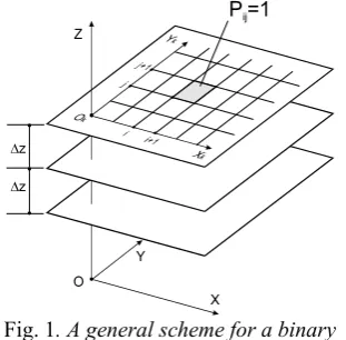
The volume of position workspace for a spatial robot is an important property since it is related with the position capabilities. Therefore, in this work the position workspace is considered as a suitable design criterion and it is computed by means of a kinematic model of a robot for all the feasible configurations of the actuators. A discretization of the workspace in suitable grids is implemented as proposed in [23] in order to compute the volume of position workspace in a computationally efficient manner. This method splits the workspace in several cross-section planes and calculates the volume as the sum workspace slice volumes in the form
(
)
max max
1 1 1
z i j n
pos k ij
k i j
V z P x y
= = =
⎛ ⎞
= Δ ⎜ Δ Δ ⎟
⎝ ⎠
∑
∑ ∑
, (10)where Δx, Δy are the grid size and Δz is the slice size. Pij is a constant value that becomes equal to
one if the (i, j) cell belongs to the workspace (Pij=1), otherwise it is equal to zero (Pij=0). In
Fig. 1, a general scheme of workspace evaluation is shown with the grid representation slice size.
Fig. 1. A general scheme for a binary representation and evaluation of manipulator
workspace
Thus, the expression of position workspace volume performance will be given by
(
)
2 _
f (X)= −1 Vpos/Vpos max , (11) in which Vpos_max stands for a maximum
reference position workspace volume that can be considered as equal to the average volume of position workspace for a human arm.
2.1.3Orientation Workspace Volume
Orientation workspace volume is also very important as it is related to robot orientation
capability. It can be computed similarly to Eqs. (10) and (11) that have been proposed for the position workspace. For the orientation workspace, the discretization is made in terms of Euler angles φ, θ, ψ, about X, Y, and Z-axis. The relationship for the orientation volume computation can be written in the form:
(
)
max max
1 1 1
z
i j
n
or ij
z i j
V ψ O ϕ θ
= = =
⎛ ⎞
= Δ ⎜ Δ Δ ⎟
⎝ ⎠
∑
∑ ∑
, (12)where Δφ, Δθ are the grid sizes for the Euler angles about X and Y-axis and Δψ is the slice dimension about the Z-axis.
Thus, the expression of orientation workspace volume performance can be given by
(
)
3
f (X)= −1 Vor/Vor_max , (13)
in which Vor_maxstands for a maximum reference
orientation workspace volume that can be considered equal to the average volume of orientation workspace for a human arm. Additionally, one can compute the manipulability performance, when position and orientation workspace cannot be treated independently, as proposed in [24].
Both position and orientation workspaces are computed as based on a kinematic model. Thus, the same design constraints in Eqs. (8) and (9) holds also for the computation of the orientation workspace.
2.2 Path Planning
Path planning can be considered as the way to obtain a trajectory between an initial and final point [23]. The path position of a serial robot is specified in terms of the end-effector position in the Cartesian space. Different trajectories can be performed by means of actuators in order to determine a path of the end-effector from a start point to a goal point. Polynomial splines are used to represent the joint position as the function of time. In [13] B-Spline functions are used to obtain joint trajectories for industrial robots. Cubic Splines are widely used for interpolation since they ensure speed and acceleration continuity [25]. In this work a 2-polynomial has been used in order to fulfill the design requirements.
defined by two points in Cartesian coordinates. Thus, an optimal criterion can be formulated as
(
)
4
f (X)= −1 tpath/tstraight , (14)
where tpath is the time that takes the robot to run
the trajectory and tstraight is the time that the robot
will take to run a straight line trajectory. The position of the ith motor can be considered as a
second order polynomial in the form
2
0 1 2
( )= + +
i i i i
q t a a t a t , (15)
where aij are coefficients, which are calculated as
based on the conditions
0
( 0)
i i
q t= =q , (16)
0
( 0)
i i
q t& = =ω , (17)
0
( 0)
i i
q t= =α
&& , (18) with qi0, ωi0 and αi0 being the initial position,
rotational velocity and rotational acceleration in Joint Space. In particular, the value qi0 is obtained
from the initial position in Cartesian space Xs=[xs, ys, zs]T by means of the inverse
kinematics. Similarly, the values ωi0 and αi0, are
evaluated from the kinematics at the starting point of the path.
The workspace characteristics depend on the link lengths, which can be considered as optimization parameters. A reasonable choice to assume as Xs start point is a robot position in
which all actuators are in the zero position (qi=0).
Then, goal point Xgoal can be chosen as a point,
which is located at a fixed distance d, from the starting point. However, distance d has to satisfy the constraint equation:
(
) (
2) (
2)
2g s g s g s
d= x −x + y −y + z −z . (19)
The value of distance d can be reasonably assumed for the service robot as equal to the maximum feasible movement of an average human arm, which can be set as equal to 0.2 m.
One should also note that the whole trajectory from the start point to the goal point should belong to the robot workspace. Therefore, additional constraint equations can be added to Eq. (14) accordingly. In particular, a trajectory belonging to the workspace should satisfy the constraint condition:
0≤qi ≤2π . (20)
On the other hand, limiting restrictions in the movement actuators must be fulfilled as
related to velocity, acceleration and jerk that can be expressed as:
max
i i
q& ≤ω , (21)
max
i i
q ≤α
&& , (22)
i imax
q ≤γ
&&& , (23) with prescribed maximum values of joint velocities ωmax, accelerations αmax, and jerks γmax,
respectively.
2.3 Lightweight Design
A service robot should have a lightweight structure for cost reduction purposes and also for safety reasons since it interacts with human beings. In fact, a large mass of the links produces large inertias that can be the source of injuries to human beings. In addition, the larger the mass of links is, the bigger the size, power consumption and the cost of actuators will be. Moreover, several service robots are expected to carry batteries on board. In this case, a large power consumption of a motor will also decrease the autonomy of the robot.
Thus, a reasonable and computationally efficient expression of the lightweight design criterion can be given as referring to mass characteristics in the form:
5
f (X) 1 T
d
M M
= − , (24)
where MT is the overall mass of a robot and Md is
the desired overall mass of the same robot that can be the minimum possible value. Moreover,
MT can be computed as the sum of the mass of
links Mi, the mass of actuators Mj, and the mass
of cables and sensors Mk, as:
1 1 1
component link actuator l
n m
T i j k
i j k
M M M M
= = =
=
∑
+∑
+∑
. (25)It is worth noting that the most critical part for obtaining a lightweight mechanical design is to reduce the weight of links and actuators. In fact, cables and sensors are usually market components with a given size and mass. Similarly, actuators can be selected from market components, but size and mass mainly depend on the desired performance in terms of output power. Therefore, a reasonable choice for Md can be to
set it as equal to the sum of the guess mass of the motors Mj, cables and sensors Mk. In this way, the
indirectly minimize the actuation torque and the motor masses (in the actuator selection process).
One should note that the mass of the links can be easily related with their volumes and density. Thus, the minimization process given by Eq. (24) will attempt to reduce link lengths and cross section sizes. Nevertheless, a constraint should be added in the form:
min 0
i i
A −A < , (26)
where Aiis the cross section area of ith link and
Aimin is the minimum acceptable cross section
area for ith link. The constraints given by Eq. (26)
are needed for obtaining cross sections of links over a minimum area whose value depends on manufacturing constraints and strength limits.
2.4. Stiffness
The lightweight optimal design criterion tries to reduce the weight of motors and links. Nevertheless, if the links are very thin and lightweight they cannot be considered rigid such as in the case of massive industrial robots. If links are not rigid enough, the accuracy of a robot will be strongly reduced due to the large compliant displacements. Therefore, it is necessary to consider the stiffness behavior of a service robot in order to have good accuracy performance together with an as-light-as-possible design.
A reasonable and computationally efficient expression of the stiffness criterion [26] can be given by Eq. (27):
(
max d)
f (X) 1= − ΔS ΔS , (27)
where ΔSmax and ΔSd are the maximum and design compliant displacements along X, Y, and Z-axes, respectively. One should note that ΔSmax
and ΔSd are also related to the maximum expected accuracy and the design accuracy of a robot. Thus, the stiffness criterion in Eq. (27) can be seen also as a criterion to optimize the mechanical accuracy of a robot along and about X, Y, and Z-axes. Thus, one can write Eq. (27) as:
(
)
6 max
f (X) 1= − ΔX ΔXd , (28)
(
)
7 max
f (X) 1= − ΔY ΔYd , (29)
(
)
8 max
f (X) 1= − ΔZ ΔZd , (30)
(
)
9 max
f (X) 1= − Δϕ Δϕd , (31)
(
)
10 max
f (X) 1= − Δψ Δψd , (32)
(
)
11 max
f (X) 1= − Δθ Δθd . (33)
The stiffness properties of a manipulator can be defined through a 6x6 matrix that is called ‘Cartesian stiffness matrix K’. This matrix gives the relation between the vector of the compliant
displacements:
[
]
TS= X, Y, Z, , ,
Δ Δ Δ Δ Δϕ Δψ Δθ occurring at the
system’s end-effector when a static wrench
T x y z x y z
W = F , F , F ,T ,T ,T⎡⎣ ⎤⎦ acts upon it, and W itself in the form
6 6
K(q) :ℜ → ℜ , W K S= Δ , (34)
ΔS=K-1ΔW, (35)
where K-1 is equal to the so called “compliance
matrix”. It is worth noting that Eq. (35) can be obtained from Eq. (34) if and only if:
det K ≠0. (36) Therefore, Eq. (36) should be assumed as an additional constraint equation in order to avoid singularities on the stiffness matrix K.
2.5 Safety
acceleration. It can be mathematically expressed as:
( )
2(
)
1
2.5
2 1 2 1
1 d t
h h
t
HIC a a t t t
t t
⎡ ⎤
=⎢ ⎥ −
−
⎢ ⎥
⎣
∫
⎦ , (37)where ah is a resultant head acceleration that takes
into account all the head acceleration components; and t2, t1 are selected so that they
maximize HIC [28].
An evaluation that is similar to the above-mentioned head injury criterion could be used also for evaluating the safety performance of a service robot at the design stage. Nevertheless, in crash tests, ah is experimentally measured while
in a design process one should provide a numerical estimation of this value. In order to obtain an expression for the optimization design process, the basic case of a single rigid joint moving at uniform velocity v before impact can be used and has been proposed in [29],
3 7
3
5
4 4
2
2
2
2 cov T
oper T oper
K M
HIC v
M M M
π
⎛ ⎞ ⎛ ⎞
⎛ ⎞
= ⎜ ⎟ ⎜⎜ ⎟ ⎜⎟ ⎜ ⎟⎟
+
⎝ ⎠ ⎝ ⎠ ⎝ ⎠
, (38)
where MT is the robot mass, Moper is the impacted
operator mass and Kcov is the lumped stiffness
coefficient of a compliant cover on the robot.
Based on the above-mentioned considerations an objective function related to the safety issue can be defined as
(
)
9
f = −1 HIC HIC/ sd , (39) where HIC can be computed through of Eq. (35) by replacing the velocity v with the end-effector standard velocity value that is computed as based on the rotational motor velocities; the HICsd can
be chosen as a design value of the head injury criterion [27].
For a maximum velocity of the end-effector of 2 m/s the HIC value can be estimated as less than 100. Thus, the maximum value of
HIC can be limited to 100 [29]:
100
HIC< . (40)
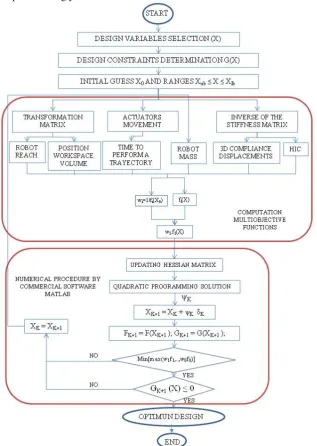
3 A NUMERICAL PROCEDURE
The main aspects of the numerical procedure to solve the proposed multi-objective optimization are described in the flowchart of Fig. 2. The proposed procedure does not guarantee the found optimal solution to be a global optimum. Therefore, a regular random grid of initial guesses
should be tested in order to overcome the problem of finding local optimal solutions.
The first step in the optimization process consists of selecting the design variables, which in this manuscript correspond to geometrical properties such as robot link lengths and equivalent areas. Then, robot constraints, and upper and lower limits of design variables must be identified in order to reduce the computational cost. In this case, design ranges can be obtained from Eqs. (8), (9) and (26). In addition, a suitable initial guess solution must be determined. In this work the MATLAB toolbox fminimax algorithm has been selected as the numerical technique to solve the formulated optimization problem.
General information about the computation of the objective functions and the numerical optimization procedure is shown in Fig. 2. In this process, preliminary data on the kinematics and physical properties of the robot are needed in order to obtain computationally efficient expressions for the objective functions. In particular, the transformation matrix from the Denavit-Hartenberg parameters, equations of the actuators movement, and stiffness matrix for a lumped parameter robot model are calculated for this reason. In addition, the weighting factors are assumed as based also on the initial guess design variables that are used for the normalization process. In fact, the output of the computation multi-objective functions will be the normalized objective functions as expressed in Eqs. (4) and (5).
On the other hand, the numerical minimax technique minimizes the worst-case value of a set of multivariable functions, starting at an initial estimate (vector X0). The minimax technique uses SQP (Sequential Quadratic Programming) to choose a merit function for the line search. The MATLAB SQP implementation consists of three main stages: Updating of the Hessian matrix of the Lagrangian function, Quadratic Programming problem Solution (QPS) and Line search and merit function calculation. The first and second stages are clearly explained in [20], the result of the QPS produces a vector Ψkwhich is used to
obtain a new iteration (Xk+1=Xk+ Ψkδk). The step
length parameter δk is determined in order to
any of the evaluations, then the loop starts again with a new iteration as shown in Fig. 2.
3.1 Case Study: SIDEMAR Manipulator for Service Tasks
The current challenge in robotics research is stated in the optimal design for robots which are able to work in daily human environments, providing aid or information. The design of a welfare robot depends strongly on the task to
perform. In case of this work, the main goal is to optimize a four link robot, which is aimed at performing tasks of attendance for people with a certain degree of handicap, as for example, approaching objects in home or offices. In Fig. 3 two schemes are presented for feasible operations of a service robot with a suitable arm when serving a glass of water, Fig. 3a), or handling a cleaning tool, Fig. 3b).
a) b)
Fig. 3. Examples of SIDEMAR applications as a service robot: a) serving a glass of water; b) with
a cleaning tool
The proposed optimization formulation has been tested with a robotic arm with two-2R modules. This robot is called SIDEMAR [30]. It has four orthogonal revolute joints as shown in Fig. 4.
The link lengths L1, L2 and equivalent
cross-section areas A1 and A2 are chosen as design
parameters for the optimization design problem. An equivalent cross-section area is obtained as the sum of link cross-section areas. Links are assumed to have a cylindrical shape. Therefore, one can write
2
2
i
i bi
d A =n ⋅ π ⋅⎜ ⎟⎛ ⎞
⎝ ⎠ , (41)
where nbi is the number of the link bars and di is
the ith diameter.
a) b)
Fig. 4. SIDEMAR manipulator: a) A 3D model; b) a prototype with one 2R module
3.2 Computation of Object Functions
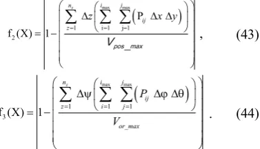
For the purpose of studying of the SIDEMAR design, the objective functions related with workspace in Eqs. (7, 11, 13) can be expressed as:
2 2 2
1
human
x y z
f (X) 1 j j j
R + +
= − , (42)
(
)
max max
1 i 1 j 1 2
P
f (X) 1
z i j
n
ij z
z x y
= = = ⎛ ⎛ ⎞⎞ Δ Δ Δ ⎜ ⎜ ⎟⎟ ⎜ ⎝ ⎠⎟ = − ⎜ ⎟ ⎜ ⎟ ⎜ ⎟ ⎝ ⎠
∑
∑ ∑
p o s︳m a x
V , (43)
(
)
max max
1 1 1
3
f (X) 1
z i j
n
ij
z i j
or_max P V = = = ⎛ ⎛ ⎞⎞ Δψ Δϕ Δθ ⎜ ⎜ ⎟⎟ ⎜ ⎝ ⎠⎟ = − ⎜ ⎟ ⎜ ⎟ ⎜ ⎟ ⎝ ⎠
∑
∑ ∑
. (44)Since the SIDEMAR design is concerned with a manipulator arm to which a wrist could be attached, the orientation capability can be considered as it is not pertaining to the SIDEMAR design. Therefore, the evaluation of f3
can be omitted in favor of reduced computational efforts of the specific design procedure.
Concerned with path planning optimization, the conditions in Eqs. (15) to (18) are calculated for each joint. Moreover, the objective function f4 in Eq. (14) has been
computed by assuming tstraight as equal to 1sec.
On the other hand, the objective function f5 in Eq. (24) can be expressed as:
4 4
1 1
5 4
1
f (X) 1
link_i act_i i i act_i i m m m = = = + = −
∑
∑
∑
, (45)where the masses in the SIDEMAR design can be calculated from the geometry of its mechanical design shown in Fig. 4 in the form:
_ _
link_i back plate forward plate i i
m =m +m +ALρ , (46)
where mlink_i is the ith link mass; mback_plate and
mforward_plate are the masses of the two circular
plates at beginning and the end of a link (see Fig. 3); ρ is material density.
The stiffness matrix for the SIDEMAR design can be calculated through the lumped parameter model in Fig. 5 by using Eq. (47). In this case, due to the SIDEMAR configuration, orientation in compliance study is not needed. Thus, it will not be considered in the present work. Therefore, simplified relationships can be derived for the stiffness matrix in the form:
T M MK J
J
K= θ , (47)
H H H H
1 2 3 4
H H H H
M
1 2 3 4
H H H H
1 2 3 4
X X X X
L L L L
Y Y Y Y
J
L L L L
Z Z Z Z
L L L L
⎡∂ ∂ ∂ ∂ ⎤
⎢∂ ∂ ∂ ∂ ⎥
⎢ ⎥
⎢∂ ∂ ∂ ∂ ⎥
= ⎢∂ ∂ ∂ ∂ ⎥
⎢ ⎥
⎢∂ ∂ ∂ ∂ ⎥
⎢ ⎥
∂ ∂ ∂ ∂
⎢ ⎥
⎣ ⎦
(48)
and
1
2
3
4
0 0 0
0 0 0
K
0 0 0
0 0 0
k k
k k
θ
⎡ ⎤
⎢ ⎥
⎢ ⎥
=⎢ ⎥
⎢ ⎥
⎣ ⎦
, (49)
with ki lumped stiffness parameters being
computed as EiAi/Li, due to the specific design of
SIDEMAR.
Therefore, the objective functions f6, f7,
and f8 in Eqs. (28) to (30) can be computed
through the computation of the maximum compliant displacements when a force is applied at point H whose x, y, z components are equal to 10 N. In fact, 10 N is a reasonable maximum payload for a service robot that is going to carry objects for a disabled person.
Fig. 5. A stiffness model for 4R of SIDEMAR design in Fig. 4
HIC criterion for safety characteristics of the SIDEMAR design can be computed as referring to Eq. (38). Moper has been considered as
the standard value of 4 kg, since it corresponds to a human head, and Kcov has been calculated as for
the last link of the SIDEMAR arm (link number four corresponding to the end-effector). Thus, one can write
x y z
max(K , K , K ) cov
K = , (50)
where Kx, Ky and Kz are the diagonal elements of
the matrix obtained from the last link (in Fig. 5): while there is no need to consider the actuator lumped parameter KT4, since it is installed on the
third link. Then, Eq. (38) can be used for computing the objective function in Eq. (39) where the desired value of head injury criterion
HICsd has been assumed to be equal to 50, which
is a value suitable to normal operation of a machine that are going to interact with humans [29].
4 NUMERICAL RESULTS
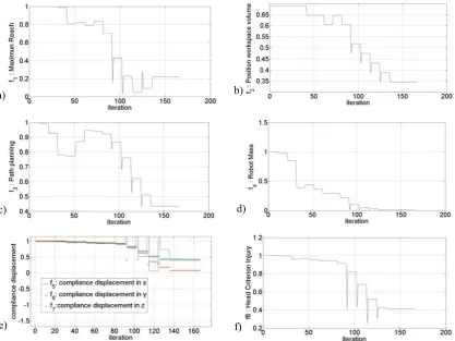
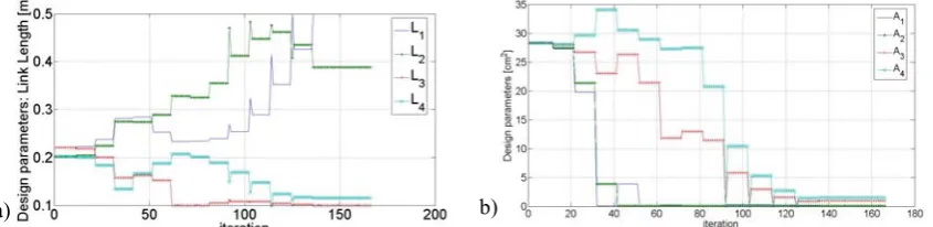
The results of the proposed design procedure as applied to 4R SIDEMAR design are reported in Figs. 6 to 9 and Tables 1 and 2. In particular, the evolution of the objective functions is reported in Fig. 6. The plots in Fig. 6 show the evolution of the objective functions converging to an optimal solution. Fig. 7 reports a global objective function as a weighted sum of the functions objective with the aim to clearly show the convergence of the optimality criteria as a whole. The numerical procedure takes less than 200 iterations to converge to an optimum solution whose parameters are reported in Table 1. The total computational time is about 60 minutes with a X86 Intel 3 MHz personal computer. The obtained optimal solution gives an increase of the first link length and a reduction of the other lengths. This optimal value increases the reach and workspace volume without causing problems to the accuracy in the movements as it can be seen in Table 2. Similar considerations hold for all the design characteristics for the optimum solution that are reported in Table 2. In particular, the results in Table 2 show also a significant reduction of the equivalent cross section areas and a reduction of one third of the robot mass by comparing the initial guess design solution with the optimal design solution that has been obtained. It should be noted that, in the optimal design solution, the enhancements of the design characteristics related to the workspace (Reach and position WS volume) and the robot lightweight are obtained also at a cost of an increment of the compliant displacements. Nevertheless, the compliant displacements are still lower than the maximum desired value (1
a) b)
c) d)
e) f)
Fig. 6. Evolution of the optimization functions versus the number of iterations for the 4R-SIDEMAR optimal design corresponding to: a) Maximum reach; b) Position Workspace Volume; c) Path planning;
d) Robot Mass; e) Three axis Compliance displacement; f) Head Criterion Injury
Table 1. Optimal design parameters for 4R-SIDEMAR design from the computations in Figs. 6 to 9
L1 [mm] L2 [mm] L3 [mm] L4 [mm] A1 [cm2] A2 [cm2] A3 [cm2] A4 [cm2] F(X)
Initial
Guess 221.0 202.2 221.0 202.2 28.0 28.0 28.0 28.0 1.0
Optimal
Value 500.0 388.2 100.0 115.6 0.13 0.13 1.01 1.53 0.2426
Table 2. Design characteristics of optimum solution Rrobot
[mm] [mVpos3] [sec] tpath [kg] MT Δ[mm] Xmax Δ[mm] Ymax Δ[mm] Zmax HIC
Initial
Guess 599.1 0.003 0.91 11.06 5.7 . 10-5 6.3 . 10-6 5.2 . 10-5 7246 Optimal
Value 783.4 0.004 0.40 4.70 1.4 . 10-3 5.9 . 10-4 1.4 . 10-3 0.3388
5 CONCLUSIONS
This paper proposes a systematic approach for designing service robots by taking into
stiffness and safety. A suitable numerically efficient multi-objective formulation and algorithm have been proposed for taking into account all the design criteria at the same time. The proposed procedure has been applied successfully to the SIDEMAR arm for service tasks. Numerical results of the optimisation process for the SIDEMAR arm show the soundness and efficiency of the proposed design procedure.
Fig. 7. Evolution of the global optimization function versus number of iterations for the
4R-SIDEMAR design
6 ACKNOWLEDGEMENTS
The financial support of the Spanish government for finance provided through the MCYT project DPI-2006-15443C02-02 is gratefully acknowledged.
5 REFERENCES
[1] IFR Robotics Newsletter (2009)
http://www.ifr.org/Mod_Newsletters/ML_Ne wsletters.asp, accessed on 2009-02-10. [2] Androidworld “World's greatest android
projects webpage” (2009).
http://www.androidworld.com, accessed on
2009-02-10.
[3] Bennewitz, M., Faber, F., Joho, D., Schreiber, M., Behnke, S. (2005). Towards a Humanoid Museum Guide Robot that Interacts with Multiple Persons. Proceedings of 5th IEEE-RAS International Conference on Humanoid Robots, p. 418-423.
[4] Meng, Q., Lee, M.H. (2006). Design issues for assistive robotics for the elderly.
Advanced Engineering Informatics, vol. 20 p. 171-186.
[5] Balaguer, C., Giménez, A., Jardón, A. (2006). The MATS robot: Service Climbing Robot for Personal Assistance, IEEE Robotics & Automation Magazine, vol. 13, n. 1, p. 51-58.
[6] Fioretti, S., Leo, T., Longhi, S. (1998). Navigation systems for increasing the autonomy and security of mobile bases for disabled people. Proceedings of the IEEE International Conference on Robotics & Automation, Leuven.
a) b)
Fig. 8. Evolution of design parameters versus number of iterations for the example of 4R-SIDEMAR: a) link length in m, b) link equivalent areas in cm2
Table 3. Objective function values of optimum solution
f1 f2 f3 f4 f5 f6 f7 f8
Initial Guess 1.0 1.0 1.0 1.0 1.0 1.0 1.0 1.0
a) b)
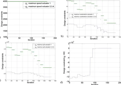
c)
d)
Fig. 9. Evolution of design constraints versus the number of iterations for the example of 4R-SIDEMAR optimal design˝, a) maximum speed of actuators, b) maximum acceleration, c) maximum jerk, d) Head
Injury Criterion (HIC)
[7] Zinn, M., Roth, B., Khatib, O., Salisbury, J. K. (2004). A new actuation approach for human friendly robot design. The International Journal of Robotic Research,
vol. 23, no. 4-5, p. 379-389.
[8] Zinn, M., Khatib, O., Roth, B., Salisbury, J. K. (2004). Playing it safe, IEEE Robotics and Automation Magazine, vol. 11, no. 2, p. 12-21.
[9] Bicchi, A., Rizzini, L., Tonietti, G. (2001). Compliant design for intrinsic safety: general issues and preliminary design.
Proceedings of the International Conference on Intelligent Robots and Systems, p. 1864-1869.
[10] Nakamura, Y. (1991). Advanced Robotics:
Redundancy and Optimization.
Addison-Wesley, Boston.
[11] Park, Y.B. (1994). Optimizing robot's service movement in a robot-centered FMC.
Computers & Industrial Engineering, vol. 27, no. 1-4, p. 47-50.
[12] Dror, M., Stulman, A. (1987). Optimizing robot's service movements: A one dimensional case. Computers & Industrial Engineering, vol. 12, no. 1, p. 39-46. [13] Gosselin, C.M. (1992). The optimum design
of robotic manipulators using dexterity indices. Robotics and autonomous systems, vol. 9, p. 213-226.
[14] Blanco, D., Castejón, C., Kadhim, S., Moreno, L. (2005). Predesign of an Anthropomorphic Lightweight Manipulator.
8th International Conference on Climbing
and Walking Robots, Clawar'05.
[15] Gao, F., Liu, X.J., Jin, S.L. (2000). Optimum design of 3-dof spherical parallel manipulators with respect to the conditioning and stiffness indices.
Mechanism and Machine Theory, vol. 35,
no. 9.
Optimization Theory and Applications, vol. 110, no.1, p. 17-34.
[17] Saramago, S.F.P., Ceccarelli, M. (2004). Effect of numerical parameters on a path planning of robots taking into account actuating energy. Mechanism and Machine Theory, vol. 39, no. 3, p. 247-270.
[18] Bischoff, R., Graefe, V. (2004). HERMES — A versatile personal robotic assistant.
Proceedings of the IEEE, vol. 92, no. 11. [19] Castejón, C., Carbone, G., García-Prada,
J.C., Ceccarelli, M., (2007). A multi-objective optimization design for a 4R Service Robot. International Journal on Mechanics and Control, vol. 8, no. 2, p. 3-8. [20] Mathworks. Optimization toolboxTM 4. User
guide. From http://www.mathworks.com/ access/helpdesk/help/pdf_doc/optim/optim_t b.pdf, accessed on 2009-02-10.
[21] Branke, J. (2008). Multiobjective optimization: interactive and evolutionary approaches, Springer, Berlin, Heidelberg. [22] Stocco, L., Salcudean, S.E., Sassani, F.
(1998). Matrix normalization for optimal robot design. IEEE International Conference on Robotics and Automation
ICRA, Leuven.
[23] Ceccarelli, M. (2004). Fundamentals of
Mechanics of Robotic Manipulation,
Kluwer, Dordrecht.
[24] Stock, M., Miller, K. (2002). Design of linear delta robot: Compromise between manipulability and workspace size. 14th
Symposium on Theory and Practice of
Robots and Manipulators, Romansy
14-Theory and Practice of Robots and Manipulators, vol. 438, p. 397-406.
[25] Piazzi, A., Visioli, A. (2000). Global Mínimum-Jerk trajectory planning of robot manipulators. IEEE Transactions on industrial electronics, vol. 47, no. 1.
[26] Carbone, G., Lim, H.O., Takanishi, A., Ceccarelli, M. (2003). Optimum Design of a New Humanoid Leg by Using Stiffness Analysis, 12th International Workshop on
Robotics in Alpe-Andria-Danube Region
RAAD, Cassino, paper 045RAAD03.
[27] Snyder, R.G. (1970). State-of-the-art – human impact tolerances, SAE 700398.
International Automobile Safety Conference Compendium.
[28] McHenry, B.G. (2004). Head Injury Criterion and the ATB. ATB Users' Conference.
[29] Bicchi, A., Tonietti, G. (2004). Fast and soft-arm tactics. IEEE Robotics & Automation Magazine, vol. 11, no. 2, p. 22-33.
[30] Castejón, C., Giménez, A., Jardón, A., Rubio, H., García-Prada, J.C., Balaguer, C. (2005). Integrated system of assisted mechatronic design for oriented computer to automatic optimising of structure of service robots (SIDEMAR). 8th International