0 INTRODUCTION
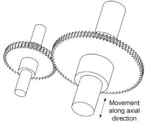
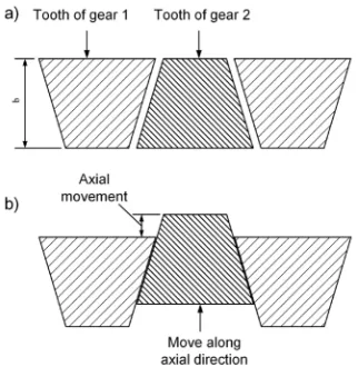
A new type of conical involute gear [1] and [2] (as shown in Fig. 1) is based on tangential modification or composite modification (includes the common modification and tangential modification; for distinguishing from the tangential modification, the common modification is called “radial modification” in this paper). When the gear is designed with composite modification, the radial modification coefficient is constant, and the tangential modification coefficient varies linearly along the axial direction. There is an angle between the two surfaces of the tooth; the backlash between two meshing surfaces can be adjusted by regulating the relative axial displacement of the meshing teeth, as shown in Figs. 2 and 3, so the vibration and noise can be weakened by eliminating or diminishing backlash. The characteristic of the unilateral tooth profile of this gear is similar to the involute helical gear.
In mechanical transmission, high mechanical efficiency can degrade heat generation, energy consumption, and air pollution [3] to [5]. Therefore, the friction loss is an important factor that should be taken into account during the design of gear transmission [6], chain system [7] and [8], and so on. The optimization of parameters and the utilization of high efficiency mechanical types are usually
considered for heightening mechanical efficiency [3] and [5]. Recently, the application of new materials [9] and [10] and a mixture of different transmission types [11] has become an effective method to decrease friction loss in mechanical transmission.
Fig. 1. The new type of conical involute gear
Fig. 2. The 3D model of the external transmission
The Calculation of Meshing Efficiency
of a New Type of Conical Involute Gear
Yu, L. – Wang, G. – Zou, S.Li Yu1,3 – Guangjian Wang1,2,* – Shuaidong Zou1,3
1 Chongqing University, State Key Laboratory of Mechanical Transmissions, China 2 Chongqing University, College of Automotive Engineering, China 3 Chongqing University, College of Mechanical Engineering, China
A new type of conical involute gear, proposed in this paper, can be applied in precise gear transmission for adjusting the backlash because of the special characteristics of its teeth. The meshing states of parallel external gear transmission based on the proposed gears are analysed and presented. The expressions of the length of contact and relative sliding velocity at any meshing position are derived. Then, the calculation formula of meshing efficiency is given by utilizing the piecewise equivalent method. Next, the variation of the length of contact line, unit load, meshing efficiency in a meshing period with different gear parameters and different operations are illustrated by employing numerical examples, and the influences of gear parameters and operations on meshing efficiency of the proposed gears are discussed based on the computing results. In the end, the applicability of the calculation is introduced.
Key words: conical involute gear, gear transmission, tangential modification, meshing efficiency
Highlights
• A new type of conical involute gear for anti-backlash is introduced.
Fig. 3. Unfolded figure at the cylindrical surface of pitch circle, a) without axial movement, b) with axial movement
In gear transmission, the computation of efficiency can offer references for the design of gear parameters. Improving the efficiency of the gear system is beneficial to reduce frictional heat generation within the gearbox and relieve gear failure modes, such as scoring and pitting [12]. The friction losses caused by sliding and rolling were computed, and the actual loss along the meshing line, considering all friction factors, were studied in [13]. Petry-Johnson et al. [12] proposed the way to measure the efficiency of spur gears under high speed and variable loads. The mechanical efficiency of parallel-axis gear pairs and cross-axis gear pairs were calculated in [14] and [15], the gear contact analysis model and a new friction coefficient formula based on Newtonian thermal elasto-hydrodynamic lubrication are applied. The sliding friction loss of helical gear transmission was computed, and the influences of helical gear parameters on meshing efficiency were studied in [16] to [19]. Seetharaman and Kahraman [20] and Luke and Olver [21] made correlative analysis and estimations of load-independent spin power losses in gear transmission. Seetharaman and Kahraman [20] and Diab et al. [22] developed numerical investigations on load-independent air-pumping power losses.
Although the meshing process of the proposed gears is the same as an involute helical gear when the rotating direction is unchangeable, the current calculation of meshing efficiency of a helical gear usually utilized the equivalent method, such as considering the helical gear as equivalent to a spur gear. The calculations mainly focused on the total efficiency of the meshing circle without illustrating the instantaneous variation of the meshing efficiency during the meshing processing. Generally, the change of the mount of meshing teeth was not considered.
This paper studied the calculation of the meshing efficiency of the proposed gear. Firstly, the meshing process of this gear is presented in detail, and the calculating method of meshing efficiency is given. Secondly, according to the numerical calculation, the influence of gear parameters and operations on meshing efficiency is discussed. Finally, the comparison between the results in this paper and relative references is illustrated.
1 ANALYSIS OF MESHING PROCESS
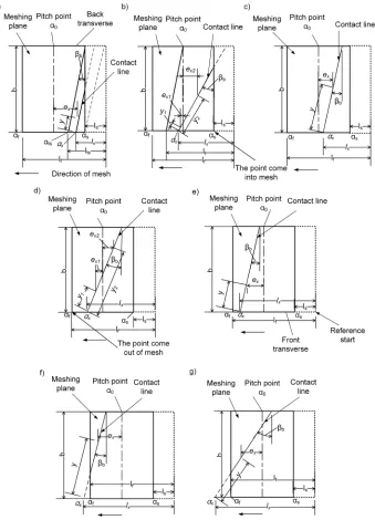
The tooth surfaces of the new type of conical involute gear are helical because of the linearly variable tangential modification along the axial direction, as shown in Fig. 1. As illustrated in Fig. 4, the root of front transverse of pinion meshes first, and then the whole tooth comes into mesh until the top of the tooth in the back transverse departs from mesh. Currently, the influences of assembled and manufactured errors on efficiency in gear transmission are difficult to quantify, and the effects of the errors such as tiny eccentricity error on efficiency is very limited, so the assembled and manufactured errors are not considered in this analysis.Considering the factors such as tooth width, helical angle and length of meshing line, the probable meshing states can be expressed as seven types in Fig. 5. Defining the tangent point of the base circle and meshing line in the front transverse as the reference start, which is shown in Figs. 4 and 5, the distance between any meshing point and the reference start at any moment can be expressed as lx = rbtanαx,
which is indicated in Figs. 4 and 5.
Fig. 4. The meshing process in the front transverse
L=
( ) / sin
/ cos
lx−ls β ls≤ ≤lx lts
β
b
b bb
b b
lts< lx≤lf
−
/ cosβ (llx− < ≤l
l l l
f) / sin f tf
,
βb x
(1)
where ls, lf, lts and ltf can be obtained through the
following expressions:
l = r tans b αs, (2)
l = r tanf b αf, (3)
l = l + btants s βb, (4)
l = l + btantf f βb. (5)
In Eqs. (2) and (3), αs and αf can be computed based on the gear parameters.
At any meshing moment, the relative sliding velocity of any meshing point on the contact line can be expressed as:
vs=
+ − + ∈
+ −
( / ) ( sin ) [ ]
( / )
1 1 1 1
0 1 0 1
i l l ,l
i l
0 b s 0
ω β
ω
l y l
l
x x
x
0
0 b 0 t
0 b l l i l − ∈ + − − y l
l y l
x
x x
sin [ ,
( / ) ( sin )
β
ω β
]
1 1 0 1 ∈∈
+ − − ∈
( / )i (l l sin ) [ , ][ ,l ll lt f ]
f 0 b f tf
1 1 0 ω1 y β lx
,, (6)
where ω1 is the angular velocity of the pinion, lt is
distance between the meshing point and the reference start in the front transverse while the back transverse meshes across the pitch point, i0,l0 and lt can be
obtained as below:
i0=z2/z1, (7)
l0=rbtanα0, (8)
lt = +l0 btanβb, (9)
where α0 is the engagement angle at pitch circle, and
α0 is 20° when the radial modification is zero, as shown in Fig. 5.
According to Eqs. (1) to (5), the length of contact line is available during a meshing circle, and the whole meshing process could be divided into many micro-segments, so the variation of the length of contact line is obtained. On the basis of Eq. (6), the relative sliding velocity of any meshing point on contact line is available, and its variation along the contact line and meshing line can be acquired by considering the gear consists of many micro-pieces along the axial direction.
2 THE CALCULATION OF MESHING EFFICIENCY
In actual application, if the input power is constant, the meshing efficiency can be derived by computing the power of sliding friction.
The power of sliding friction is caused by the common action of the relative sliding between the meshing surfaces and the load on the surfaces, which is also affected by the coefficient of friction between the surfaces, these relationships can be illustrated by the following expression:
Pf =µFvs. (10)
In most of the engagement process, the number of meshing teeth is more than one, and the calculation of the total length of contact lines usually involves two or more pairs of teeth and their meshing position on the meshing line. According to Eq. (10), the power of sliding friction of meshing points varies instantaneously along with the position on contact line and meshing line.
2.1 Calculation of Unit Load
To simplify the calculation, the load distribution of teeth is thought to be uniform, which means the effect of the deformation and stiffness of the teeth is not considered, so the unit load can be expressed as:
F
L
ei= M
i rb k 0 1 ∗ =
∑
kN , (11)
where Lk is the length of the contact line of the kth
meshing tooth, N is the number of the meshing teeth. If the position of the meshing point in the front transverse of reference tooth is expressed as lx1, the
position of the meshing point in the front transverse of the kth meshing tooth before the reference tooth can be
derived by the formula below:
lxi =lx1+k* pb. (12)
Quoting the result of Eq. (12), the length of the contact line of the kth meshing tooth is available with
Eq. (1), and the unit load also can be computed with Eq. (11).
2.2 Calculation of Relative Sliding Velocity
Fig. 5. The probable meshing states; a)the meshing point in front transverse doesn’t arrive at the pitch point and the tooth partly comes into mesh; b) the meshing point in front transverse has meshed across the pitch point, but the tooth does not totally come into mesh; c) the meshing point in front transverse does not arrive at the pitch point while the whole tooth is in mesh; d) the meshing point in front transverse
has meshed across the pitch point, and the meshing point in back transverse has not arrived at the pitch point, while the whole tooth is in mesh; e) the meshing points in the back transverse have meshed across the pitch point while the whole tooth is in mesh; f) the meshing point in the back transverse has meshed across the pitch point while the tooth has partly meshed out; g) the meshing point in back transverse has
as the reference, the position of any meshing point on contact line along meshing line can be denoted as:
lxi=lx1+k* pb−yksinβb, (13)
where yk is the distance between any meshing point
of the kth meshing tooth to the front transverse along
contact line.
So the relative sliding velocity of any meshing point on the contact line of the kth tooth at any moment
can be derived by taking Eq. (13) into Eq. (6).
2.3 Friction Coefficient
The friction coefficient is an important factor in calculating the power of sliding friction, which depends on the load, parameters of gear, the surface roughness of tooth, lubrication, lubricant viscosity, and other factors. Although the empirical formulas for calculating the coefficient of friction were summarized with the theoretical derivation and experimental model in [23] to [33], these studies were usually had certain limitations because of the difficulties of actual test and the influence of multi-factors, so it is still difficult to propose a generally applicable formula and exactly test in practice. This paper referred the mean coefficient of friction in [4], [31] to [33], which is described as follows:
µ
υ ρ η
= 0.048(F b) R X
c c 0.2
L bt
Σ
−0 05. 0 25.
,
a (14)
where XL is the lubricant factor, considering XL =1
for mineral oil here [30] and [32], Ra is the surface
roughness, and υΣc can be calculated as:
υΣc= ⋅ ⋅2 υt sinα0.
From Eq. (14), it can be observed that the friction coefficient is constant during the meshing process when the gear parameters and operations are definite. At the same time, the gear parameters and operations are the main determinants of the coefficient of friction. Thus, the influence of gear parameters and operations on meshing efficiency can be well studied. In contrast, the utilization of Eq. (14) is also helpful for comparing the computing results of efficiency with the results calculated by the method in [4].
2.4 The Computation of Meshing Efficiency
According to the computation mentioned before, setting the front transverse as reference, dividing the gear into m pieces along contact line and considering
the meshing line made up of n segments, the instantaneous power of sliding friction loss of any micro gear piece can be expressed as:
Pfkij=µFei∆yυskij. (15)
In Eq. (15), υskij is the sliding velocity at
any meshing point on the contact line, subscript
k = 1, 2, …, N, which means the code of meshing teeth, and subscript i = 1, 2, …, m, j = 1, 2, …, n, which indicate the position of the meshing point on the contact line and meshing line respectively. Thus, the power of the sliding friction of a single tooth at any meshing position is,
Pfki F yei skij m
=
i=1
µ
∑
∆υ . (16)Based on Eq. (16), the computation of total power of sliding friction at any meshing position is shown below:
PΣfi = Pfki
k N
=
∑
1
. (17)
Therefore, if the sliding friction is the main consideration, the instantaneous meshing efficiency can be computed as:
η= 1 P
−PΣfi
. (18)
3 CALCULATION RESULTS OF NUMERICAL EXAMPLE
Based on the calculation of meshing efficiency during the meshing process derived above, the computation was carried out with detail gear parameters.
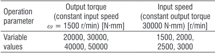
Table 1 illustrates the reference and variable value of modulus, helical angle and radial modification. When one parameter varies, the other parameters remain consistent with the reference value, so the analysis and calculation with single variation is available. The output torque is 50000 N·mm and input speed is 955.4 r/min when the discussions concentrate on the variation of gear parameters. Table 2 expresses the different output torque and input speed while the gear parameters are the reference values in Table 1.
meshing in, line 2 is the process from the whole reference tooth coming into mesh to the meshing point arriving at the pitch point, line 3 indicates the meshing state of reference tooth from the meshing point in front transverse at pitch point to the end of a meshing period; the three meshing processes are recorded with red, green and black separately. It can be observed that the right black part in the third process is longer than the left, which illustrates the reference tooth meshing with single tooth near the end of the meshing period when the tooth before the reference tooth has meshed out, and this also can be known by the variation of length of contact line and unit load in Figs. 6c and d.
Table 2. The different operation values
Operation parameter
Output torque (constant input speed ω = 1500 r/min) [N·mm]
Input speed (constant output torque
30000 N·mm) [r/min] Variable
values
20000, 30000, 40000, 50000
1500, 2000, 2500, 3000
When the output torque is constant, the variation of the length of contact line is in contrast with the unit load. Fig. 6b shows the curve of meshing efficiency varying with the position of meshing point in the front transverse of the reference tooth along the meshing line. Referring to Fig. 6a, it can be observed that meshing efficiency is constant when there are two teeth meshing with the whole tooth. In this period, the contact lines of two teeth are at different sides of the pitch point, as the states illustrated in Figs. 5c and e, so the decrements of ex in Fig. 5c is equal to the
increments of ex in Fig. 5e, which leads to the inverse
variation of relative sliding velocity of two meshing teeth. Otherwise, the length of the contact line increases gradually partly during the mesh-in period in the front transverse because of the existence of helical angle, and the unit load decreases during this process. However, the meshing efficiency decreases in this period, meshing points are far from the pitch point, and the relative slide is serious. The same phenomenon also appears when the tooth before the reference tooth is meshing out, but the decrease of the length of contact line leads to the increase of meshing efficiency.
Fig. 6. When the gear parameters are reference value; a) the variation of relative sliding velocity, b) the variation of meshing efficiency, c) the variation of total length of contact line,
d) the variation of unit load
Fig. 7. The variation with different modulus, a) length of contact line, b) unit load, c) meshing efficiency, d) coefficient of friction
and the length of meshing line
In Fig. 7 is shown the variation of the length of contact line, the unit load and the meshing efficiency along the meshing line with different modulus, for avoiding the zero-tooth thickness at the back transverse, the width of the tooth is 10 mm. In Fig. 7a, the maximum length of contact line is identical when the modulus varies, and the length of meshing Table 1. The reference value and variation of gear parameters
Gear parameters
Teeth number of pinion z1
Teeth number of gear z2
Pressure angle α [º]
Modulus
[mm] Width of tooth [mm]
Helical angle β [º]
The radial modification coefficient of pinion (zero transmission)
Reference value 45 80 20 2 20 3 0
line and the radius of base circle increases with the increase of modulus. Thus, the unit load decreases with the increase of modulus, and the maximum relative sliding velocity increases with the increase of modulus while the operation is fixed. In contrast, the increase of modulus leads to the decrease of positive force and increase of the relative radius of curvature, therefore, the coefficient of friction decreases with the increase of the modulus by Eq. (14). The influences of unit load and relative sliding velocity acting on the meshing efficiency are opposite, so the variation of meshing efficiency is mainly due to the change of the coefficient of friction with different modulus.
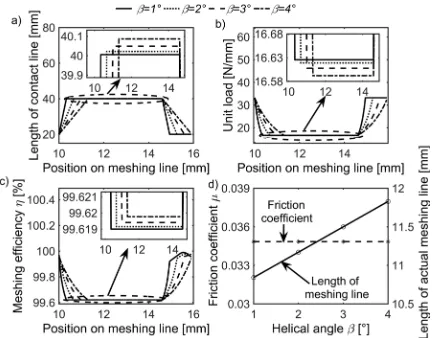
Fig. 8 indicates the variation of the length of contact line, the unit load, coefficient of friction, the length of meshing line and the meshing efficiency along the meshing line with different helical angle, and the partial detail figures are given in Figs. 8a to c. As Fig. 8a shows, the length of contact line increases with the increase of the helical angle when the whole tooth is meshing, and the unit load decreases with the increase of the helical angle in this period. Furthermore, the instantaneous minimum meshing efficiency increases with the helical angle, as Fig. 8c illustrated, but the mean meshing efficiency in a period decrease with the helical, as Table 3 shows. Because the length of actual meshing line lengthens with the helical angle, so does friction loss during meshing in and meshing out increases.
Fig. 8. The variation with different helical angles, a) length of contact line, b) unit load, c) meshing efficiency,
d) coefficient of friction and the length of meshing line
The variations of the length of contact line, unit load, coefficient of friction, the length of meshing line and meshing efficiency with different radial modification of pinion are obtained in Fig. 9, and the radial modification of gear is opposite to the
pinion. The radial modification affects the meshing start, meshing destination, and the relative meshing position between the meshing teeth in different meshing periods, so the variation of relative sliding velocity caused by the change of meshing position is the main influence factor of meshing efficiency. When the radial modification of pinion is negative, the smaller modification leads to the longer distance between the meshing start and the pitch point, which results in higher relative sliding velocity during the mesh-in process, so the meshing efficiency decreases, as shown in Fig. 9c. When the modification of pinion is positive, the bigger radial modification leads to the longer distance between the meshing destination and the pitch point, which results in higher relative sliding velocity, so the curve of the meshing efficiency during the mesh-out period appears as a wave trough when the modification is 0.3.
Fig. 9. The variation with different modifications of pinion, a) length of contact line, b) unit load, c) meshing efficiency, d) enlarged figure of meshing efficiency, e) coefficient of friction
and the length of meshing line
As Figs. 10 and 11 show, the curves of meshing efficiency are provided by setting the output torque and input speed as variations. When the output torque is constant, the output power and the relative sliding velocity enlarge with the increase of the input speed, which means the increase of P and PΣfi in Eq. (14),
the input speed is fixed, the effect of the increase of output torque on the P and PΣfi in Eq. (18) is the same
as above, but the increase of output torque leads to the enlargement of friction coefficient, so the meshing efficiency decreases along with the increase of output torque at the same input speed as illustrated in Fig. 11. The variations of the meshing efficiency under different operations have good agreement with the trends of experimental results in [19].
Fig. 10. The variation of meshing efficiency at different input speeds; a) meshing efficiency, b) coefficient of friction
Fig. 11. The variation of meshing efficiency at different out torques; a) meshing efficiency, b) coefficient of friction
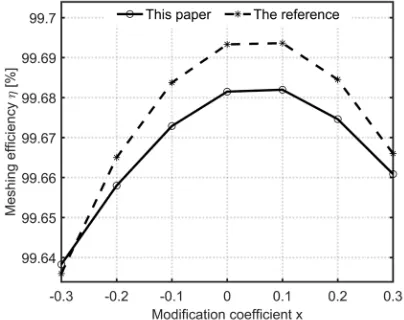
Fig. 12. The comparison between calculating results in this paper and the results obtained by calculation in reference [4]
To validate our calculation, the comparison between the results in this paper and the meshing efficiency calculated by the method in [4] is carried
out, and the detail is presented in Fig. 12 and Table 3. Based on the same gear parameters, the variation of mean efficiency computed by our method is closed to the efficiency calculated according to the method in [4] with different modification coefficient, as shown in Fig. 12. Furthermore, the comparisons are carried out when different modulus, helical angle and operations are considered, the corresponding results are listed in Table 3. In Table 3, the ηfc is the friction power loss
computed in the current paper, ηfr is the friction power
loss calculated with the formula in reference [4], and Er represents the percentage of the error between two
differently calculated results.
Table 3. Comparison of friction power loss obtained by two calculating methods in our paper and reference [4]
Variation of parameter
or operation ηfc [%] ηfr [%] Er [%]
Different modulus [mm]
1 0.556 0.534 0.041
2 0.359 0.352 0.020
3 0.280 0.276 0.015
Different helical angle [°]
1 0.310 0.306 0.013
2 0.314 0.307 0.025
3 0.319 0.307 0.039
4 0.323 0.307 0.052
Different input speed [r/min]
1500 0.263 0.253 0.039
2000 0.248 0.240 0.034
2500 0.237 0.228 0.039
3000 0.229 0.220 0.040
Different output torque [N·mm]
20000 0.242 0.233 0.039
30000 0.263 0.253 0.039
40000 0.278 0.268 0.039
50000 0.291 0.280 0.039
4 CONCLUSION
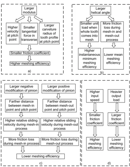
The meshing efficiency of the proposed gear was calculated by dividing contact line and meshing line into micro-segments, and the variations of sliding velocity, contact line and unit load in a meshing period are illustrated. The variation of the length of contact line, unit load and instantaneous meshing efficiency are studied by considering the modulus, helical angles and modification coefficient as variables.In addition, the variations of meshing efficiency with different input speed and output torque were also discussed. The influences of parameters and operations on efficiency can be summarized as in Fig. 13.
efficiency under heavy load. A larger helical angle increases loss during mesh-in and mesh-out processes; therefore, choosing little helical angle can reduce friction loss while the anti-backlash requirement is satisfied. Modification may increase the relative slide in the mesh-in or mesh-out period, thus, little positive or negative modification should be considered in design. In contrast, maintaining high input speed is beneficial for heightening meshing efficiency.
Fig. 13. The influence of gear parameters and operations on meshing efficiency: a) modulus, b) helical angle, c) modification
coefficient, d) operations
Although the calculation of meshing efficiency presented in this paper is based on the new type of conical involute gear, the meshing process of helical gear is similar to the new type of conical involute gear, so the calculation can also apply in computing the meshing efficiency of helical gear when the influence of the tooth deformation on unit load is not taken into account.
5 ACKNOWLEDGEMENTS
This research received financial support from The National Natural Science Foundation of China (contract No. 51275538).
6 NOMENCLATURES
b width of tooth, [mm]
F positive force, [N]
Fei unit load, [N/mm]
i0 transmission ratio
L length of contact line, [mm]
l0 distance between pitch point and reference point,
[mm]
lf distance between meshing point in front
transverse and reference point along meshing line when the tooth begins to mesh out, [mm]
ls distance between meshing point in front
transverse and reference point along meshing line when the tooth begins to come into mesh, [mm] ltf distance between virtual meshing point in front
transverse and reference point along meshing line when whole tooth comes out of mesh, [mm] lts distance between meshing point in front
transverse and reference point along meshing line when whole tooth just comes across pitch point, [mm]
lx distance between any meshing point in front
transverse and reference point along meshing line, [mm]
M output torque, [N·mm] P input power, [W]
Pf power of sliding friction, [W]
pb base pitch in transverse, [mm]
rb radius of base circle of pinion, [mm] vs relative sliding velocity, [m/s]
υΣc the sum of the tangential velocity at pitch point,
[m/s]
Fbt the transverse force in tangent, [N]
y the distance between the meshing point and front transverse along, [mm]
Δy the length of micro-segment along contact line, [mm]
XL lubricant factor
z1 teeth number of pinion
z2 teeth number of gear
α0 engagement angle at pitch circle, [°]
αf engagement angle in front transverse when the tooth begins to mesh out, [°]
αs engagement angle in front transverse when the tooth begins to come into mesh, [°]
αx engagement angle in front transverse at any
moment, [°]
βb helical angle of base circle, [°] η meshing efficiency
ρc curvature radius of the tooth profile at the pitch point in transverse, [mm]
Subscripts
i the position of meshing point along contact line
j the position of meshing point along meshing line in front transverse
k the number of meshing teeth
7 REFERENCES
[1] Wang, G.J., Chen, X.A. (2008). Variable tooth thickness cylindrical modified gear and its application in transmission device. Patent CN 101285520A, China.
[2] Yu, L., Wang, G.J., He, L.L. (2015). The electrically controlling anti-backlash based on variable tooth thickness gear. The International Conference on Gears, p. 591-600.
[3] Kakavas, I., Olver, A.V., Dini, D. (2016). Hypoid gear vehicle axle efficiency. Tribology International, vol. 101, p. 314-323,
DOI:10.1016/j.triboint.2016.04.030.
[4] Baglioni, S., Cianetti, F., Landi, L. (2012). Influence of the addendum modification on spur gear efficiency. Mechanism and Machine Theory, vol. 49, p. 216-233, DOI:10.1016/j. mechmach-theory.2011.10.007.
[5] Kolivand, M., Li, S., Kahraman, A. (2010). Prediction of mechanical gear mesh efficiency of hypoid gear pairs.
Mechanism and Machine Theory, vol. 45, p. 1568-1582,
DOI:10.1016/j.mechmachtheory.2010.06.015.
[6] Perić, S., Nedić, B., Trifković, D., Vuruna, M. (2013). An
experimental study of the tribological characteristics of engine and gear transmission oils. Strojniški vestnik - Journal of Mechanical Engineering, vol. 59, no. 7-8, p. 443-450,
DOI:10.5545/sv-jme.2012.870.
[7] Calì, M., Sequenzia, G., Oliveri, S.M., Fatuzzo, G. (2016). Meshing angles evaluation of silent chain drive by numerical analysis and experimental test. Meccanica, vol. 51, p. 475-489, DOI:10.1007/s11012-015-0230-0.
[8] Cheng, Y.B., Wang, Y., Li, L., Yin, S.B., An, L.C., Wang, X. P (2015). Design method of dual phase Hy-Vo silent chain transmission system. Strojniški vestnik - Journal of Mechanical Engineering, vol. 61, no. 4, p. 237-244, DOI:10.5545/sv-jme.2014.2318.
[9] Li, X.M., Sosa, M., Andersson, M., Olofsson, U. (2016). A study of the efficiency of spur gears made of powder metallurgy materials – ground versus super-finished surfaces.
Tribology International, vol. 95, p. 211-220, DOI:10.1016/j. triboint.2015.11.021.
[10] Duhovnik, J., Zorko, D., Sedej, L. (2016). The effect of the teeth profile shape on polymer gear pair properties. Technical Gazette, vol. 23, no. 1, p. 199-207, DOI:10.17559/TV-20151028072528.
[11] Rossetti, A., Macor, A. (2013). Multi-objective optimization of hydro-mechanical power split transmissions. Mechanism and Machine Theory, vol. 62, p. 112-128, DOI:10.1016/j. mechmachtheory.2012.11.009.
[12] Petry-Johnson, T.T., Kahraman, A., Anderson, N.E., Chase, D.R. (2007). An experiment investigation of spur gear efficiency.
Journal of Mechanical Design, vol. 130, no. 6, p. 1-10,
DOI:10.1115/1.2898876.
[13] Michlin, Y., Myunster, V. (2002). Determination of power loss in gear transmissions with rolling and sliding friction incorporated. Mechanism and Machine Theory, vol. 37, no. 2, p. 167-174, DOI:10.1016/S0094-114X(01)00070-2.
[14] Xu, H., Kahraman, A., Anderson, N.E., Maddock, D.G. (2007). Prediction of mechanical efficiency of parallel-axis gear pairs.
Journal of Mechanical Design, vol. 129, no. 1, p. 58-68,
DOI:10.1115/1.2359478.
[15] Xu, H. (2005). Development of a Generalized Mechanical Efficiency Prediction Methodology for Gear Pairs. PhD Thesis, Ohio State University, Columbus.
[16] Wang, C., Fang, Z.D, Jia, H.T. (2009). Calculation of sliding friction loss of helical gear. Journal of Yanshan University, vol. 33, no. 2, p. 99-102, DOI:10.3969/j.issn.1007-791X.2009.02.002.
[17] Wang, C., Gao, C.Q., Cui, H.Y. (2012). The selection of helical cylindrical gear parameters based on meshing efficiency.
Journal of Yanshan University, vol.36, no. 2, p. 126-130,
DOl:10.3969/j.issn.1007-791X.2012.02.006.
[18] Marques, P.T.M., Martins, R.C., Seabra, J.H.O. (2016). Power loss and load distribution models including frictional effects for spur and helical gears. Mechanism and Machine Theory, vol. 96, p. 1-25, DOI:10.1016/j.mechmachtheory.2015.09.005.
[19] Aarthy, V., Tech, B. (2009). An experimental investigation of helical gear efficiency. MSc Thesis, Ohio State University, Columbus.
[20] Seetharaman, S., Kahraman, A. (2009). Load-independent spin power losses of a spur gear pair: model formulation. Journal of Tribology, vol. 131, no. 2, p. 1-11,
DOI:10.1115/1.3085943.
[21] Luke, P., Olver, A.V. (1999). A study of churning losses
in dip-lubricated spur gears. Proceedings of the
Institution of Mechanical Engineers, Part G: Journal of Aerospace Engineering, vol. 213, no. 5, p. 337-346,
DOI:10.1243/0954410991533061.
[22] Diab, Y., Ville, F., Houjoh, H., Sainsot, P., Velex, P. (2005). Experimental and numerical investigations on the air-pumping phenomenon in high-speed spur and helical gears.
Proceedings of the Institution of Mechanical Engineers, Part C: Journal of Mechanical Engineering Science, vol. 219, no. 8, p. 785-800, DOI:10.1243/095440605X31652.
[23] Benedict, G.H., Kelley, B.W. (1961). Instantaneous coefficients of gear tooth friction. ASLE Transactions, vol. 4, no. 1, p. 59-70, DOI:10.1080/05698196108972420.
[24] O’Donoghue, J.P., Cameron, A. (1966). Friction and temperature in rolling sliding contacts. Tribology Transactions, vol. 9, no. 2, p. 186-194, DOI:10.1080/05698196608972134.
[25] Drozdov, Y.N., Gavrikov, Y.A. (1968). Friction and scoring under the conditions of simultaneous rolling and sliding of bodies. Wear, vol. 11, no. 4, p. 291-302, DOI:10.1016/0043-1648(68)90177-4.
[26] Martin, K.F. (1978). A review of friction predictions in gear teeth. Wear, vol. 49, no. 2, p. 201-238, DOI:10.1016/0043-1648(78)90088-1.
rolling line contacts using a deterministic model. Tribology International, vol. 34, no. 10, p. 713-722, DOI:10.1016/ S0301-679X(01)00066-4.
[28] Cioc, C., Cioc, S., Moraru, L., Kahraman, A., Keith, T.G.Jr. (2002). A deterministic elastohydrodynamic lubrication model of high-speed rotorcraft transmission components.
Tribology Transactions, vol. 45, no. 4, p. 556-562,
DOI:10.1080/10402000208982587.
[29] ISO/TR 13989-1:2000(E). Calculation of Scuffing Load Capacity of Cylindrical, Bevel and Hypoid Gears – Part 1: Flash Temperature Method. International Organization for Standardization, Geneva.
[30] Martinsa, R., Seabra, J., Brito, A., Seyfert, Ch., Luther, R., Igartua, A (2006). Friction coefficient in FZG gears lubricated with industrial gear oils: Biodegradable ester vs. mineral
oil. Tribology International, vol. 39, no. 6, p. 512-521,
DOI:10.1016/j.triboint.2005.03.021.
[31] Martins, R.C., Cardoso, N.F.R., Bock, H., Igartua, A. Seabra, J.H.O. (2009). Power loss performance of high pressure nitrided steel gears. Tribology International, vol. 42, no. 11-12, p. 1807-1815, DOI:10.1016/j.triboint.2009.03.006.
[32] Fernandes, C.M.C.G, Martins, R.C., Seabra, J.H.O. (2014). Torque loss of type C40 FZG gears lubricated with wind turbine gear oils. Tribology International, vol. 70, p. 83-93,
DOI:10.1016/j.triboint.2013.10.003.
[33] Magalhães, L., Martins, R., Locateli, C., Seabra, J. (2010). Influence of tooth profile and oil formulation on gear power loss. Tribology International, vol. 43, no. 10, p. 1861-1871,