University of New Orleans University of New Orleans
ScholarWorks@UNO
ScholarWorks@UNO
University of New Orleans Theses and
Dissertations Dissertations and Theses
12-17-2004
Dynamic Website and Data Engine Generators for Distributed
Dynamic Website and Data Engine Generators for Distributed
Enterprise/Business Architectures
Enterprise/Business Architectures
Fareed Qaddoura University of New Orleans
Follow this and additional works at: https://scholarworks.uno.edu/td
Recommended Citation Recommended Citation
Qaddoura, Fareed, "Dynamic Website and Data Engine Generators for Distributed Enterprise/Business Architectures" (2004). University of New Orleans Theses and Dissertations. 195.
https://scholarworks.uno.edu/td/195
This Thesis is protected by copyright and/or related rights. It has been brought to you by ScholarWorks@UNO with permission from the rights-holder(s). You are free to use this Thesis in any way that is permitted by the copyright and related rights legislation that applies to your use. For other uses you need to obtain permission from the rights-holder(s) directly, unless additional rights are indicated by a Creative Commons license in the record and/or on the work itself.
DYNAMIC WEBSITE AND DATA ENGINE GENERATORS
FOR DISTRIBUTED ENTERPRISE/BUSINESS
ARCHITECTURES
A Thesis
Submitted to the Graduate Faculty of the
University of New Orleans
in partial fulfillment of the
requirements for the degree of
Masters of Science
in
The Department of Computer Science
By
Fareed A. Qaddoura
B.S, Birzeit University, Palestine, 2001
This thesis is dedicated to my parents,
my wife,
Soondus and Tasneem
Acknowledgment
I would like to thank my advisor Prof. Mahdi Abdelguerfi for the time and resources he provided to make this project come to life.
In addition, I would like to thank Prof. Shengru Tu and Dr. Nauman Chaudhry for being on my thesis defense committee.
Table of Contents
List of Figures ... vii
List of Tables ...ix
Abstract ... x
Chapter 1 Introduction ... 1
1.1 The Benchmark Data Engine Components ... 2
1.2 Motivation ... 3
1.3 Overview ... 4
Chapter 2 Concepts of Website and Data Engine Generators ... 6
2.1 Portal Application ... 6
2.2 Data Engine Generator ... 7
2.3 Website Generator ... 8
Chapter 3 Architecture and Design ... 9
3.1 Technical Architecture ... 10
3.2 Technology Used ... 11
3.3 Functional Architecture ... 14
Chapter 4 System Catalog ... 17
4.1 System Catalog Tables ... 17
4.2 System Catalog E/R Diagram... 19
Chapter 5 Portal Application ... 25
5.1 Mechanisms of the Portal Application ... 25
5.2 “My Portal Application”... 27
5.3 Design and Implementation... 29
6.2 Service Integration Applet ... 39
6.3 Design and Implementation... 48
Chapter 7 Website Generation ... 50
7.1 Website Generator Concepts ... 50
7.2 Design and Implementation... 51
Chapter 8 Security and Auditing ... 56
8.1 User Login JSP Bean... 56
8.2 Session Management ... 58
8.3 User Privileges and Component Access ... 61
Chapter 9 Results and Conclusions ... 67
9.1 Results and Conclusions ... 67
References ... 69
Appendix ... 70
A.1 New Service Integration Using XML ... 70
A.2 Copyright Permission ... 72
List of Figures
Figure 1.1 General architecture of the “Benchmark Data Engine ” ... 3
Figure 3.1 General overview of the portal application ... 9
Figure 3.2 Portal application architecture ... 13
Figure 3.3.1 Functional architecture of the verification process ... 14
Figure 3.3.2 Functional architecture of the server session handler ... 15
Figure 3.3.3 Functional architecture of the new service integration applet ... 15
Figure 3.3.4 Functional architecture of the website generator ... 16
Figure 4.2.1 System catalog E/R diagram 1 ... 20
Figure 4.2.2 System catalog E/R diagram 2 ... 21
Figure 4.2.3 System catalog E/R diagram 3 ... 22
Figure 4.2.4 System catalog E/R diagram 4 ... 23
Figure 4.2.5 System catalog E/R diagrams alignment ... 23
Figure 5.1.1 Portal application main web page ... 26
Figure 5.1.2 Main page flowchart ... 27
Figure 5.2.1 “My Portal Application” diagram 1 ... 28
Figure 5.2.2 “My Portal Application” diagram 2 ... 29
Figure 5.3.1 Snapshot of H_SEC_USER_LOGS table ... 30
Figure 5.3.2 Portal application class interactions ... 31
Figure 6.1.1 Test case data model ... 34
Figure 6.1.2 Primary–Detail model ... 35
Figure 6.1.3 Primary–Lookup model ... 36
Figure 6.1.4 Detail–Lookup model ... 37
Figure 6.1.5 Primary – Primary – Detail model ... 38
Figure 6.1.6 Primary – Primary model ... 39
Figure 6.2.1 Test case model ... 40
Figure 6.2.2 Service Tables ... 41
Figure 6.2.3 Table Attributes 1 ... 42
Figure 6.2.6 Table Attributes 4 ... 44
Figure 6.2.7 Table Attributes 5 ... 44
Figure 6.2.8 User Defined Referential Integrities ... 45
Figure 6.2.9 System Generated Referential Integrities 1 ... 46
Figure 6.2.10 System Generated Referential Integrities 2 ... 46
Figure 6.2.11 Schema’s creation credentials ... 47
Figure 6.2.12 Service Created ... 48
Figure 6.3.1 “New Service Integration” class diagr am ... 49
Figure 7.2.1 Service web page class diagram ... 52
Figure 7.2.2 Customers Form ... 53
Figure 7.2.3 Resources Form ... 54
Figure 7.2.4 Resource-Types form ... 54
Figure 7.2.5 Schedule-Details form... 55
Figure 8.1.1 Security Header file ... 57
Figure 8.2.1 Session Management Classes Model ... 59
Figure 8.2.2 Tomcat web.xml Modified Header ... 60
Figure 8.2.3 User Authentication – server side – ... 61
Figure 8.2.4 User Logging off – server side – ... 61
Figure 8.3.1 Create User Account Form ... 62
Figure 8.3.2 Update User Account Form... 63
Figure 8.3.3 Reset Password Form ... 63
Figure 8.3.4 Set Screen Access Form ... 64
Figure 8.3.5 Set Attribute Access Form ... 65
Figure 8.3.6 Selected Domain User Form ... 66
List of Tables
Abstract
Creating websites providing dynamic services is an extensive process. Intelligent systems are used to create websites with dynamic services. Current intelligent systems are hard to use and configure by the average user. The generated websites are usually custom built to solve one problem and cannot be fully customizable for users on different environments.
This thesis presents a technological solution that enables the average user to create websites with dynamic services by providing a number of parameters. The website generator is a web-based application that generates all the components of the website. The components act as portlets and the generated website will be the portal application.
The data engine generator creates the website’s underlying database. To enable distributed enterprise/business architecture, the data engine generator records the metadata about the database and the website to be generated.
Chapter 1 Introduction
In the year 2002, the Computer Scienc e Department initiated a research project entitled “An Intelligent Benchmark Data Engine for the Maritime Industry”1. The research was motivated by the need of performance benchmarks of the services provided by the maritime industry companies. They wanted to know how efficient and effective their services are. They wanted to know what is the customers feedback regarding the quality of their services.
Most of the maritime companies are small and serve few vessels only. It will be a huge financial burden to create IT departments to benchmark the service time, quality of service, customers’ satisfaction and monitor their growth.
The research initial focus was on creating a flexible web-based benchmark data engine for the maritime industry. The goal was to implement an Intelligent Site Generator capable of generating entire new site with all their components based on a number of parameters given by the user. This will help the economical growth of the maritime industry by reducing the cost of operation
The goals of the research were to start with the maritime industry and then generalize the result to any kind of service. The research aimed to find an intelligent way to get the public or the customers to give their feedbacks on the quality of the service. Finally, to allow businesses/enterprises use this architecture to facilitate their data exchange and distribution.
In the first stages of the project, a prototype of a manual website generator was created. It did support the creation of one database table and one webpage. In the second
1
stage, two components where created and built on the prototype of the website generator. The first component was called SagaMap (Semi Automatic Schema Generation and Mapping). The second component was called ChartVisio.
1.1
The Benchmark Data Engine Components
The Benchmark Engine components facilitated the generation of a simple webpage, modify the underlying database structure, and visualize the data. The site generator creates the webpage; SagaMap allows the modification of the database structure and ChartVisio to visualize the data.
Site Generator: is a component on the server side that dynamically generates at compile-time all the elements required for the webpage. Then, it uses the stored elements of the webpage at run-time.
SagaMap: is a tool that works towards providing an interface to accept from users all the required information to generate a new database. It creates an empty data warehouse. For a given source database, the tool aims at arriving at an appropriate mapping to create a structurally related warehouse. After a mapping has been formalized, tables for the new warehouse are created. Then, relevant data is automatically transported from the source database to the newly created warehouse.
Figure 1.1 shows the architecture of the Benchmark Data Engine
Figure 1.1 General architecture of the “Benchmark Data Engine ”
1.2
Motivation
for a metadata repository we called “System Catalog”. Any changes in the environment will be recorded in this set of database tables and the components in the system will adapt accordingly.
This also motivated the need to have a framework where the new components add to the system can be presented to the users. The framework should be configurable to control what the users would see and interact with. The framework is called “Portal Application”.
Creating one database table per service is not realistic for a real life company. This gave the motivation to create a new “Data Engine Generator” that enables the creation of more than one database table. The Data Engine Generator ensures that the relations between the tables are in third normal form. The users’ interface to the “Data Engine Generator” is a standalone component we called “New Service Integration”. The “New Service Integration” is an example of a portlet component.
As a result, the “Website Generator” has to be changed. The “Website Generator” is recreated to accomplish two things:
a. Generate a complete website that allows the users to handle the database tables.
b. Create the web pages with dynamic contents that adapts to the changes in the system environment.
Finally, security and auditing mechanisms are implemented to ensure that the data and the resources assigned to the users are not tampered or vandalized.
1.3 Overview
Chapter 2 Concepts of Website and Data Engine
Generators
Current technological solutions attempt to minimize the effort needed for their implementation. It is clear that the decision to implement a certain solution is highly motivated by its financial cost and the modifications needed to the current infrastructure. As a result, many solution providers offer their customers the resources and the infrastructure hosting.
2.1 Portal Application
The solution is packaged together in what is called “Portal Application”. Portal applications are off the shelf packages that can be personalized and customized to meet the business and the user needs. Portlets are the building components of a portal application. Each portlet is responsible for a set of tasks. New developed portlets are added to the portal application without the need for any additional programmatic effort.
In general, the requirements for deploying a portal application are an application server2 and a database server. Cell phones, handheld mobile devices, desktops and laptops are examples of devices that may be used to interact with a portal application.
Portal applications should ease the data flow between business entities. They should be dynamic and customizable by the business manager and to a certain degree by the users.
Some of the most common and widely used portal applications include “My MSN” from MSN® or “My YAHOO!” from YAHOO!®. These are examples of portal applications that can be customized and personalized to the user needs. However, these portal applications do not have a business portlet where data exchange among business
2
entit ies can be established. On the other hand, IBM® WebSphere portal application is an example of a portal application that handles on demand business. Oracle® has a portal application that is dedicated to accessing and organizing the enterprise information and applications. Other portal applications like Novell® Portal application, MEDiAPPS® NET portal, and Sun Microsystems Java System Portal Server 6 and many others combine the features of a portal application for user and business interaction.
Unfortunately, the development of highly generic portlets is tedious. Highly generic portlets limit the user and business needs because of the ir generality. Special purpose portlets are not designed to operate in different settings than the ones used to create it. In conclusion, the portlet should allow the users to customize it to their needs and work with their environments.
2.2 Data Engine Generator
Our portal application, posses all the advantages of a portal application with the added benefit of simplicity in creating a portlet that will handle the data organization, data access, and the applications interaction with the data. Users who are not experienced with the concepts of database analysis, design and implementation will be able to create their own business portlets.
The “Data Engine Generator” is a component that was developed and deployed on
2.3 Website Generator
After the users of the portal application create their own database, the website engine generator deployed on the application server will dynamically create a set of web pages that have the capabilities to retrieve and insert data into the database.
Chapter 3 Architecture and Design
The architecture explains the design decisions that were taken in order to achieve a truly cost effective, simple, easy to use, secure, reliable, and scalable portal application. The design supports the distributed enterprise or corporate architecture as well as the one location business in terms of database distribution and horizontal fragmentation. Scalability is achieved by using replicated web servers and distributed database architecture.
In this chapter, we will discuss the technical architecture of the portal application in terms of interaction among the system components, the functional architecture including the deployed components and their interactions, and the technology used.
3.1 Technical Architecture
The components appearing in the general overview of the portal application in Figure 3.1 are:
Verification: is the set of operations that perform the user authentication by verifying a set of credentials submitted by the user through the portal application website.
System Catalog: The system catalog is the metadata holder. It contains
information about the users, users’ accounts, users’ privileges, available resources, resources locations, and portlets. The metadata is inserted in a set of database tables. Storing this metadata allows the portal application to work with any database management system. Moreover, even if the database management system is capable of retrieving the metadata about the created schemas, the cost to interpret and parse the retuned metadata is much greater than, if the metadata is stored directly in the database. Storing metadata about the users’ database schemas in special database tables outperforms the use of the database management system to retrieve the metadata and then process it. In other words, there is no need to use any API to retrieve the metadata, it is a direct read operation from the database. Finally, the system catalog contains metadata about not only the users and their privileges, but also about the portlets and their components which emphasis the need for this structural component.
Operational Database: is the database that receives the transactional data of the business entities.
schemas; then it interacts with the “Website Generator” to generate the set of web pages for interaction with the database.
The developed portlet’s functionality is defined by the user. It is important to note that users with enough privileges should be able to configure the portlets’ operation modes and the database tables involved. This enforces that the portlet itself is enabled to function in a configurable manner. It is very crucial to point that the model complies with our understanding of the prototype of the coming generation of portlets imposed by the on demand business solution development and deployment requirements. This prototype requires a portlet to operate on any platform, perform the tasks on any set of data, and interact if necessary with any existing operational database. Clearly, these portlets will have the intelligence to be used and to operate with minimal requirements of training. To complete the picture portlets are expected to be able to generate portlets by minimal user interaction and minimal set of specifications.
The portal application allows portlets to be integrated in the system without any extra programming effort. This will result in two types of portlets, one set, which is already defined in the portal application, and another set, which is created by the users.
3.2 Technology Used
Most of the components are built using the Java™ programming language. Java provides platform independence. In addition, Java has many web application development capabilities that do not need any intermediate components to run on the web server.
The technologies used in this project are:
Java Swing: are components used to build the graphical user interface. Swing
four tabs organized and structured as a wizard application to guide the user through the process of creating and integrating a new service.
Java Applets: are java programs that have the ability to be executed through the web browser by embedding them in an HTML page. Applets run on the client side and have the capability of requesting and posting data to the server side.
Java Servlets: are Java programs that are used to extend the functionality of a web server. Servlets can be thought of as Java applets running on the server side. Servlets are used to handle the Java Applet requests and to provide the data for the web pages with a dynamic content.
JSP: or Java Server Pages: are used to create web pages with dynamic contents. JSP creates the dynamic content. JSP gets the dynamic content by executing the JSP code and/or tags on the server side. Client’s requests cause the execution of the JSP code and then the result is displayed with the dynamic content on the client side. JSP is used in all the web pages of the portal application.
Jakarta Tomcat: is the web server used as the container or host for Java Servlet and JSP. It is used as the platform for deploying web applications and web services. This web server will manage the user sessions and fire a set of events whenever a user is terminating or invalidating the session, that is, closing the browser or logging out of the system.
Oracle 9i: is used as the database management system. The data engine generates and executes the SQL commands to create and integrate the new schema. It is also used to store the metadata of the portal application system.
JavaScript: is a scripting language that is used to improve the design and validate
the web pages displayed on the client side.
CSS: or Cascading Style Sheets: are definitions used to tell the web browser how to display the HTML elements. They can be embedded in the web page or stored separately in external files called CSS files. External and embedded CSS definitions are used to format the look of the web application web pages.
DHTML/DOM: or Dynamic HTML/Dynamic Object Model: Technologies that allow the web page to have a dynamic content that can be manipulated by a set of events fired from user interaction with the web page. The DOM defines a set of methods to access and manipulate HTML objects. The DHTML and DOM together reduce the traffic time from and to the server by having the ability to add components to the web page without sending any server request.
Figure 3.2 shows how the above technologies are combined together in the portal application architecture.
3.3 Functional Architecture
The functional architecture describes the deployed components and their interactions. The focus here will be on the UML®1 diagrams to explain the interactions and will go further more into the details in the following chapters. The UML diagrams used in this section describe the packages that literally encapsulate the code used to perform the set of tasks required by the users or the system.
The root package is called benchmark because of the initial focus of this project
“Benchmarking for the Maritime Industry”. The users try to login to the system and a set of commands is generated to accomplish this task. The user login class interacts with the database login module to verify the user credentials. Using the same package the users with appropriate privileges will be able to retrieve the necessary data to manage their profiles by interacting with the profiles management servlet. Figure 3.3.1 models the functional architecture of the verification process and the user interactions with the profiles management.
Figure 3.3.1 Functional architecture of the verification process
1
Users’ sessions and the login information are maintained and recorded on the server for auditing and security purposes. The auditing is done by inserting the user login information in database tables that have the log files structure. The server package will be described in more details in Chapter 9.
Figure 3.3.2 models the functional architecture of the server session handler.
Figure 3.3.2 Functional architecture of the server session handler
In order to proof the concept of portal applications a portlet was created to allow users to create their own database schema. The portlet server component will invoke website generator, which in turn will generate the corresponding web pages. The users interact with a Java applet. The applet validates the user input and then communicates with the server side internally to create the database schema using the “Data Engine
Generator”. Figure 3.3.3 models the functional architecture of the new service
integration
The new service integration portlet communicates with the server side, which in turns forward the data posted by the applet to the service normalization data base module. The module will insert the metadata in the system catalog and create the database schema. Later it calls the website generator to create the necessary web pages to handle the created database schema. The website generator generates (in addition to the generated website) two utility classes and a servlet and deploys the website automatically at the web server. No user interaction is needed for the deployment of the generated website. The newly generated website is considered as a new portlet. In Figure 3.1 “Resources” and “Orders” are two different portlets created by the users. Figure 3.3.4 models the functional architecture of the website generator.
Chapter 4 System Catalog
The system catalog is the metadata holder. It contains informatio n about the users, users’ accounts, users’ privileges, available resources, resources locations, and portlets. The metadata is inserted in a set of database tables. Storing this metadata allows the portal application to work with any database management system. Moreover, even if the database management system is capable of retrieving the metadata about the created schemas, the cost to interpret and parse the retuned metadata is much greater than, if the metadata is stored it directly in the database. Storing metadata about the users’ database schemas in special database tables outperforms the use of the database management system to retrieve the metadata and then process it. Finally, the system catalog contains metadata about not only the users and their privileges, but also, about the portlets and their components which emphasizes the need for this structural component.
4.1 System Catalog Tables
The system catalog is composed of twenty database tables. The tables in the system catalog are listed in Table 4.1 below:
Table Name Table Name Table Name
H_SEC_USER_LOGS SEC_USER_LOGS SRV_TABLE_TYPES
SEC_COMPANY_PROFILES SEC_USER_SCREENS SRV_USER_TABLES
SEC_MODULES SEC_USER_STATUS STP_PORTAL_STYLES
SEC_SCREENS SEC_USER_TYPES STP_SERVICE_PARAMETERS
SEC_SCREEN_TABLES SRV_DATA_TYPES STP_USER_SCREEN_STYLES
SEC_USERS SRV_TABLE_ATTRIBUTES STP_USER_SERVICES
SEC_USER_ATTRIBUTES SRV_TABLE_FOREIGN_KEYS
Tables that start with the prefix H are history tables. Tables that start with the prefix SEC are security tables. Tables that start with the prefix SRV are service tables. Tables that start with the prefix STP are Setup tables.
The above tables can be replicated at different database servers as long as the system catalog connection parameters files place on the tomcat server is modified to point to the new location of the system catalog. The system catalog can be horizontally fragmented when more than one web server is running the portal application so the load is distributed.
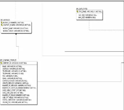
The main tables in the system catalog are:
SEC_COMPANY_PROFILES: this table is used whenever a new business, corporate or enterprise subscribes to benefit from the portal application and its portlets.
SEC_USERS: this table has the user accounts and specifies the type of the user by using the stored values of user types in the table SEC_USER_TYPES. The user status determines if the user is Active, Inactive, and Locked; these values are stored in the table SEC_USER_STATUS. The tables SEC_USER_SCREENS and SEC_USER_ATTRIBUTES are used to define which web pages and which attributes or components the user can interact with when using a certain webpage. SEC_USER_LOGS is the table of the currently logged users. When the user logs off the SEC_USER_LOGS records are modified and moved to the history log table H_SEC_USER_LOGS.
STP_SERVICE_PARAMETERS: is the main table in the system that keeps track of the location of the database schemas that the users create or can access. The new schema is interchangeably used in this context with the term “Service”. This table allows the DBA administrators to move the databases wherever they want or refer to the databases at the users’ side, without the need for any programming effort.
STP_PORTAL_STYLES: holds the CSS used to format the user’s environment. Each user can customize the portal application main page to meet their needs.
SEC_SCREEN_TABLES: specifies the tables associated with the ge nerated website for the users of the portal application. SEC_MODULES is a literal packaging for the screens that perform a set of relevant task. SEC_SCREENS is the table that holds the web pages created for the users automatically and the portlets in the system.
SRV_DATA_TYPES: is a lookup table that has the definitions of all possible datatypes in the system and their sizes. The listed datatypes and sizes are supported by Oracle 9i. The supported datatypes by the “Data Engine Generator” are the primitive datatypes.
4.2 System Catalog E/R Diagram
Figure 4.2.1 System catalog E/R diagram 1 shows the first quarter of the whole E/R diagram.
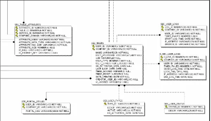
Figure 4.2.2 System catalog E/R diagram 2 shows the second quarter of the whole E/R diagram.
Figure 4.2.3 System catalog E/R diagram 3 shows the third quarter of the whole E/R diagram.
Figure 4.2.4 System catalog E/R diagram 4 shows the fourth quarter of the whole E/R diagram.
Figure 4.2.4 System catalog E/R diagram 4
In order to align the system catalog E/R diagram quarters follow the Figure 4.2.5, which shows how to align the four quarters.
Figure 4.2.1 Figure 4.2.2
Figure 4.2.3 Figure 4.2.4
Figure 4.2.5 System catalog E/R diagram alignment
System scalability and the ease of administration is achieved by maintaining pointers to the resources and their locations. The tables STP_SERVICE_PARAMETERS, SEC_COMPANY_PROFILES, SEC_SCREENS and SEC_USERS are the main tables where all the relations are drawn into or exported from. These tables can be used to distribute the system or add new users or components.
Chapter 5 Portal Application
Current technological solutions attempt to minimize the effort needed for their implementation. It is clear that the decision to implement a certain solution is highly motivated by its financial cost and the modifications needed to the current infrastructure. As a result, many solution providers offer their customers the resources and the infrastructure hosting.
The solution is packaged together in what is called “Portal Application”. Portal applications are off the shelf packages that can be persona lized and customized to meet the business and the user needs. Portlets are the building components of a portal application. Each portlet is responsible for a set of tasks. New developed portlets are added to the portal application without the need for any programmatic effort.
5.1 Mechanisms of the Portal Application
The portal application operates on the client side of the client server architecture. In other words, when the user opens the web browser and navigates through the internet to the portal application’s website, the user is considered the client in the client server architecture. When the portal application main page is called –usually the index page –, it searches the cookies1 on the client side for the last logged user name and company domain2.
The user will be required to log on to the portal application by providing a valid username, password, and company domain. If the user credentials combinations are correct then the portal application calls the users portal page.
1
Cookies: are files stored on the client side to remember some parameters values that may have been used by the user and may be used again. So the user may change the background color of a certain website and whenever the user navigates back to the site the background color information is retrieved for the cookies and assigned to the website background color.
2
Figure 5.1.1 shows the main page of the portal application where the users are expected to provide the system with their login credentials.
Figure 5.1.2 shows the flowchart of the algorithm used in the portal application main page.
Figure 5.1.2 Main page flowchart
5.2 My Portal Application
Figures 5.2.1 and 5.2.2 show two different portal applications for two different users in two different companies. Note that if the user has a CSS stored in the STP_PORTAL_STYLES as in Figure 5.2.1, it will be loaded from the database. Otherwise, the default CSS will be read from the portal application directory on the web server. It is easy to note that the two users have different privileges to access the portlets and services. The user “davem” in Figure 5.2.1 has the privileges just to login to the system while the user “fareed” in Figure 5.2.2 has a menu of the accessible portlets and services.
Figure 5.2.2 “My Portal Application” diagram 2
5.3 Design and Implementation
The portal application main page is a JSP file that creates a JSP bean1. The bean is going to live as long as the session is valid and will keep the username, company domain and if the verification method of the user have failed or succeeded.
The portal application itself is also a JSP that interacts with the user’s data defined in the system catalog to load the right privileges. The portal application generates the menus and the links to the resources during load time by creating a set of html tags that will represent the menus. A set of JavaScript functions with DHTML/DOM is embedded in the portal’s application main page, to make the menus show and hide on mouse rollovers and mouse exit.
1
The user will logout from the portal application either by clicking on the logout link, by closing the browser, or by being idle for a period of time without using the web page. The user’s log time, location, how many failed attempts before actually logged in, and the logout time are stored in the log tables SEC_USER_LOGS and H_SEC_USER_LOGS described earlier in the system catalog. If the user fails three times to log in to the portal application then it will be impossible for this user to re- log to the portal application before the administrator resets the user status from “Locked” to “Active”.
Figure 5.3.1 shows a snapshot of the history log table H_SEC_USER_LOGS.
Figure 5.3.1 Snapshot of H_SEC_USER_LOGS table
Chapter 6 Service Integration
The main portlet in this web-application is the new service integration portlet. It enables the users to create a custom database and interact with the websit e generator to generate a set of web pages. The generated web pages allow the users to exchange data with the database and make it available for business entities access. The process in which users create the database schema is called “New Service Integration” and the server side component that facilitates this, is called “Data Engine Generator”.
The service integration portlets has four tabs organized and structured as a wizard application to guide the user through the process of creating and integrating a new service.
6.1 Service Integration Concepts
The main objective of designing and implementing the new service integration portlet is to enable users to create their own database schemas. To create the database schema, the user has to determine the functional dependencies 1. This requirement would make it very hard to argue that the portal application will reduce the cost of operation, so all the necessary validations were embedded inside the portlet to make sure that it can intuitively derive the functional dependencies from the user description of the schema’s tables.
The functional dependencies are very important for designing the database in the third normal form2. The third normal form ensures that the primary key – unique identifier for each record in the table – is unique enough to identify every record in the
1
Functional dependencies: if for each value in a relation there is a set of values determined in another relation then we say that the second relation is functionally dependent on the first; i.e. the primary key in a relation determines all other non-key attributes.
2
database table. None of the other attributes should be part of the primary key or independent from the primary key (candidate key). It would be very hard for the users to define the functional dependency so the user is provided with a multi-step wizard and a set of messages that guide the user during the process of creating the database schema.
The portlets assumed that the users would be able to understand what a database table is. It also assumes that the user will be able to list the tables, which will correspond maybe to a spreadsheet or a form that is used in the user business entities and to be modeled in the newly integrated database schema, referred to as “Service” here in.
The functional dependencies are used to generate the minimal set of foreign keys needed to ensure that the physical database schema is in the third normal form. Three types of tables are defined for this purpose:
1. Primary table : is a table that holds the header records for a detail table. This term is interchangeable with the term Master Relation in DB glossaries. This table can reference lookup tables and create foreign keys to another primary table. One attribute can be the primary key.
2. Detail table:is a table that holds the record(s) for a master record in a primary table. This table must have a minimum of one reference to a primary table and a maximum of two references to two different primary tables. More than one attribute can be used as the primary key. The primary key of the primary table should be used in the detail table whether it is part of the primary key or just a not null attribute.
Figure 6.1.1 shows a set of tables created in a data- modeling tool that will be used as a test case for the definitions above. In the rest of this chapter, the relations of this test case model will be examined.
Figure 6.1.1 Test case data model1
The test case model is composed of five tables. It models a resource scheduling data model. By looking at the model, it can be seen that the “Customers” and “Resource Types” table s are lookup tables – dangling with only one link. Schedule Details is a detail table for the Schedule table. Therefore, Schedule is a primary table. From our definitions above, Resources cannot be a lookup table because it has a foreign key from the Resource Types table; also, it cannot be a detail table because the primary table primary key (Schedule Id) is not used in it. Therefore, Resources is another primary table.
Can an inexperienced user derive such a model? The user is expected to be using a form, spreadsheet, report, or any kind of document in the business entity to be as the guide for deciding what tables to be created. People are using many financial packages and bookkeeping toolkits to organize their data. They learned by experience how to
1
organize their data, how to put each set of related data in the same datasheet and give them title and so on. The users of the “New Service Integration” portlet are not expected to be database designers to be able to use it. Users of the “New Service Integration” are expected to be familiar with the business entity data flows to be able to use the portlet.
To enforce the concepts of the “Data Engine Generator” outlined previously, five cases of relationships among database tables will be examined. The goal is to verify if the “Data Engine Generator” logic really complies with the above definitions. These cases are based on the possible data entities in a sample grocery store database
Case one, the relation between a primary table and a detail table: In this case, the primary key of the primary table should be a no n null attribute in the detail table or part of a composite primary key that consists of more than one attribute. The applet adds these attributes if the user forget to do so or used different attribute names. This is to enforce the one-to-many relationship between the primary and the detail table. When a record is inserted in the primary table, one or more records should be inserted at the same time. Figure 6.1.2 shows the relationship between two entities Invoices and Invoice details. The assumption made here is that you cannot issue an invoice for no activity, which implies that at least one detail record is required in each invoice detail. The primary key of the detail table should be composite if the primary key of the primary table is to considered as parts of its key.
Case two, the relation between a primary and a lookup table: in this case the primary key of the lookup table should be used as an attribute in the primary table that can be nullable. Figure 6.1.3 shows the relations ship between Invoices as a primary table and Customers as a lookup table. The Invoice must be issued to a Customer whether the customer has an account in the store database or not, but it can exclude the customer name if the payment is in cash. Some stores may restrict their services to be provided only for their customers. As a result, the attribute Customer Id should be an attribute in the Invoices table with a not null option. The main issue, in this case, is the fact that inserting a new Invoice requires that the customer id to exist in the customers table. Finally, the relationship is again one-to-many, which means that a customer can have more than one invoice.
Figure 6.1.3 Primary–Lookup model
discounts, the product may not be listed for discounts in any list price discount. Figure 6.1.4 shows the relationship between a detail and a lookup table.
Figure 6.1.4 Detail–Lookup model
Figure 6.1.5 Primary – Primary – Detail model
has a set of zip codes and so on. Defining any of the tables in between the top most level table Countries and the table in the last level let say ZIP Codes of the hierarchy will break the links and make it impossible to build this model using the system by considering the previous four cases only. Therefore, primary tables are allowed to have a foreign key reference to another primary table. Figure 6.1.6 shows the relationship diagram between the tables Provinces and Cities.
Figure 6.1.6 Primary–Primary model
6.2 Service Integration Applet
The users interact with a Java applet to create the database schema that corresponds to some or all the data needed to allow the communication between the business entities. The applet validates the user input and then communicates with the server side internally to create the database schema by utilizing the methods of the “Data Engine Generator”.
Figure 6.2.1 shows the test case data model discussed in section 6.1.1. In the discussion of the model, it was mentioned that the Schedule and Resources tables are primary tables, Schedule Details is a detail table for Schedule, Customers, and Resource Types are lookup tables.
Figure 6.2.1 Test case model
The new service integration applet is a graphical user interface built to make it easy for non-technical users to create database schemas that are relevant to their business processes and to use the generated database schema to be the container of the data exchanged among the business entities. In this section, the New Service Integration Applet will be used to create the model.
database schema will be in third normal form if not already generated, and checks if the schema’s database “Service Login Name” is used.
At each step or tab, the “New Service Integration” applet checks if the semantics of the defined schema are valid from the perspective of the DBMS (Database Management System). Validations like table name length, the datatypes used, the sizes of the attributes to be created, attribute names, same datatype and size for user defined foreign keys, and if the attributes to be referenced are primary keys1.
Step One : Define the names and the relations among the tables to be created. Figure 6.2.2 shows the tables’ definition and their relations. There is no requirements that the table specification to be in any order as long as at the end the user specifies the primary table(s) of the detail table if any. Otherwise, the “New Service Integration” will not let the user move to the next step.
Figure 6.2.2 Service tables
1
Step Two : Specify the table attributes – including the lookup table ’s primary key usage – and the primary keys. Figures 6.2.3 to 6.2.7 shows how the attributes and the primary keys are specified.
Figure 6.2.4 Table attributes 2
Figure 6.2.6 Table attributes 4
Step Three: Determine the Referential Integrities among the tables, i.e., define the foreign keys. The users can skip this step because the applet generates automatically the minimal set of referential integrities required to create the database schema in third normal form. Users can define more referential integrities than the ones generated. Figure 6.2.8 Shows a user defined referential integrity; while Figures 6.2.9 and 6.2.10 show the automatically generated referential integrities.
Figure 6.2.9 System generated referential integrities 1
Step Four: Determine the database schema name, login, password, and the displayed name of the service. The “Next” button is still enabled, so after the user specifies the new service credential the “Data Engine Generator” will check if this user exists within the same database server instance it will be created on. In Figure 6.2.11, the service name is the name that the users will see while interacting with the portal application. The service login name is the database user name and is used to create the schema. The administrator password and its confirmation are the database password for the database user to be created. If the specified credential does not conflict with an existing schema then clicking on the “Next ” button will enable the “Create” button. When the user clicks on the create button the applet sends the data to the servlet and in turn calls the “Data Engine Generator”.
Figure 6.2.11 Schema’s creation credentials
database schema on the appropriate database server, and finally calls the website generator to create the website for the new service. Figure 6.2.12 shows the result of creating the data test model introduced in section 6.1 and again in this section.
Figure 6.2.12 Service created
Substantially, allowing the users to draw the E/R diagram and make the system derive the relationships among the database tables may be a possible alternative.
6.3 Design and Implementation
tasks. The “Website Generator” creates a set of web pages to insert data in the new integrated schema (service) via the World Wide Web.
Figure 6.3.1 “New Service Integration” class diagram
The implementation of the Data Engine Generator allows it to connect to any kind of database and perform the required tasks. Standard SQL was used as much as possible except for some Oracle’s DBMS built in functions. Oracle’s functions should be checked for compliance with the standard SQL.
Chapter 7 Website Generation
After the users of the portal application create their own database, the website engine generator deployed on the application server will dynamically create a set of web pages. The generated web pages have the capabilities to retrieve and insert data into the database.
The website generator intuitively derives from the database structure the relationships among different database tables. It creates a set of web pages that ensure that users can interact with their database structure. It embeds all the necessary functionality that makes this interaction happen in a simple and secure manner.
7.1 Website Generator Concepts
The users determine the relations among the database schema tables in the “New Service Integration” applet. These definitions are very important to keep in mind, especially that they are used to generate the website’s web pages. Primary tables are standalone tables that needs separate web page to insert data, except if the primary table is referenced by one or more detail tables. In this case, they should be wrapped together in the same page with each detail table. Clearly, a detail table cannot be alone in a web page; while, a web page will be created for each lookup table.
7.2 Design and Implementation
The web pages of each service are separated in the web server directories inside a folder named after the service web pages it holds. Moreover, the service folders are located inside the company’s main folder on the web server. This file–folder organization is critical and makes all the difference for administrators when they want to move a company’s folders from one web server to another for distribution or replication considerations.
Three Java classes are created, compiled and deployed to the company’s folder and will be used by the generated web pages, after that the Java .class files are copied to the classes directory on the web server under the company’s directory. The three classes are:
Experience submission1 servlet class (ExperienceSubmissionServlet.java): this servlet handles the requests of the services web pages and posts the incoming data to the users’ database.
Database connectivity class: (DBConnections.java): this class acts as the database connection manager. It is used to create and terminate connections to the system catalog database.
Retrieve form attribute class (RetrieveFormAttributes.java): this class acts as a utility class that collects the data about the users database tables to be used in the web page. It also retrieves the user’s attributes that will be discussed more in Chapter 9.
The class diagram in Figure 7.2.1 below shows the interaction between the generated Java classes. These classes are packaged together inside the company’s domain folder on the web server.
1
Figure 7.2.1 Service web page class diagram
JSP and Java: handles security issues, session management and communications with the system catalog.
HTML: tags are used for the form and the hidden parameters used to communicate with the servlet. The form components are generated on the fly when the web page is requested by a user using the JSP and Java in the web page.
Scripts: JavaScript code is embedded to collect the user’s input, prepare the form for submit and submit the form. In case the form has a detail table, JavaScript functions are added to enable the creation or deletion of more than one detail record. This script will no t request any resource from the server. DOM is used so that the server will not take any part to reconstruct the page or add more components.
Figures 7.2.2 through 7.2.5 show the generated web pages for the test case data model. These forms will post the data to the user’s created database schema. The forms are viewed only by the set of users defined to view them, and the attributes displayed will be only the attributes with granted access to the user.
Figure 7.2.2 shows the Customers form, recall that Customers is a lookup table.
Figure 7.2.3 shows the Resources form, which is a standalone primary table.
Figure 7.2.3 Resources form.
Figure 7.2.4 shows the Resources Types form, Resources Type is a lookup table.
Figure 7.2.4 Resource-Types form.
Chapter 8 Security and Auditing
The portal application is secured at two different levels. The security is implemented on the server side components and on the business logic. The application components and the users’ databases are secured by granting access to authenticated users only. On the business logic, administrators grant or revoke access privileges to the application components.
On the server side, a set of forms and mechanisms is implemented to make sure that only authenticated users can use the portal application. To go one-step further an auditing mechanism was implemented. The necessary data for auditing is recorded with every login attempt as well as with every logout from the system. Every component accessible to users checks if the user is in a valid session. Moreover, the portal application purges out the idle users and the ir sessions will be destroyed.
A set of user interface driven components were created to enable the administrators of the system to control who can see what and how. This allows the flexibility of securing the business logic components.
In the following sections, the details covered to make this application as secure as possible are discussed. It should be noted that this project is not about security or securing web applications. Still, the application is secure enough at this level and created a framework that can be easily enhanced, upgraded, and extended.
8.1 User Login JSP Bean
The “UserLogin” JSP bean accesses and sets the state of the object instantiated from the class “UserLogin”. The main variables set by the “UserLogin” are the username, the company domain and if the user credentials are validated and verified or not.
To enhance the security design of the components of the “Portal Application”, all web pages include a pointer to the “SecurityHeader.jsp” in their header. The “SecurityHeader.jsp” checks if the user session is valid or not. In other words, did the user login to the system or not? When one web page references another JSP, the code in the included file will be interpreted as if it existed in the referencing page. In the “SecurityHeader.jsp”, if the user login credentials are not valid the system will redirect the user to the portal’s application main page. Figure 8.1.1 shows the security header file “SecurityHeader.jsp”.
Figure 8.1.1 Security header file
The statistics are important to give the indication about the users that are forgetful or that have bad intentions. When the user logs in to the system some parameters are collected from the user environment and inserted in the system catalog table SEC_USER_LOGS in the next section.
8.2 Session Management
Tomcat web server is not configured to handle sessions. Therefore, a set of functions have been implemented to manage the session creation and destruction or invalidation. The Tomcat server creates and invalidates session but no extra handling is provided.
Figure 8.2.1 shows the class model diagram for the classes implemented to manage the users’ sessions.
Even with the described classes, the Tomcat server is still not aware that these classes will manage the session. The Servlet Filter class will not filter anything unless the Tomcat notifies it about what is going on with the users’ requests. In order to make the Tomcat notify the Servlet Filter class the following modifications should be done to the web.xml configuration file from the conf directory at the Tomcat’s installation directory. Figure 8.2.2 shows the tags that are needed to force the Tomcat to forward the users’ requests to the session management classes.
Figure 8.2.2 Tomcat’s web.xml modified header
Figure 8.2.3 User authentication – server side –
Figure 8.2.4 shows what happens when the session expires or the user tries to log off.
Figure 8.2.4 User logging off – server side –
8.3 User Privileges and Component Access
Figures 8.3.1 through 8.3.5 show the forms that are used to allow the users to maintain their accounts either by direct interaction or through an administrator. Each form composes a piece in the business logic.
Figure 8.3.1 and 8.3.2 are used to create and update a user account.
Figure 8.3.1 Create user account form
Figure 8.3.2 Update user Account form
Figure 8.3.3 shows the form utilized by the users to reset their password. The default password for a new user account is the social security number of the user.
Figure 8.3.4 shows the form to grant screen or form access to the user. If the user is not an administrator then the set of screens or forms that this user is eligible to access are the screens with no admin option.
Figure 8.3.4 Set screen access form
this attribute, and from database design of view this attribute “Item’s List Price Discount” should be nullable.
The administrators use the form in Figure 8.3.6 to select the user that will have a profile update. Users are viewable for administrators under their company accounts so there is no mixing between users of different companies at all.
Chapter 9 Results and Conclusions
This chapter discusses the project results, its possible uses, and conclusions.
9.1 Results and Conclusions
The portal application had a framework of sixteen Java classes composed of almost 9000 lines of code. There is another sixteen JSP almost of the same magnitude. The system catalog has twenty tables. All of this is to accomplish the following:
a. Reduce operation cost overhead on small and medium businesses.
b. Allow enterprises to integrate their distributed architecture in a simple way, allowing their business entities to exchange data.
c. Create a framework that enables the integration of new portlets on the fly without a need to change the portal application
d. Make it easier for administrator to manage users, audit the interactions with the system, distribute the load on the web servers, and distribute the database. e. Control the user privilege to the form attribute level.
f. Allow users to customize their views and manage their profiles.
g. Create portlets that are intelligent enough to provide the users with what they need by allowing them to configure it.
h. Portlets should be able to create portlets if the desired is to create 100% user define portlets.
Some of the applications that will benefit the most by using this “Portal Application” are:
a. Definitely, the maritime industry will be able to benchmark their performance and quality of service. The same benefits can be generalized to all other industries.
b. Connect the enterprise departments that need to share information without the need to create a new infrastructure or posting all their data to one repository. This portal application is a saver in terms of resources, time, and money needed to do this kind of data exchange among the different entities in a secure and fast manner. In other words, the time needed to exchange information with the right user privileges is a matter of seconds or minutes but not weeks; the money to be saved in this process can be significant.
c. Add electronic business tier for small and medium business. The new tier will be 100% custom and dynamic to operate as defined by the creators – the users.
References
1. Ozu Tamer M, Valduiez Patric: Principles of Distributed Database Systems; second edition; Prentice Hall 1999.
2. Geary David M.: graphic JAVA Mstering the AWT, second edition, Sun Microsystems 1997.
3. Campione Mary, Walrath Kathy: the Java™ Tutorial Object–Oriented Programming for the internet, Addison Wesley 1997,
4. Sommerville Ian: Software Engineering, Addison Wesley 2001.
5. Date C. J.: An Introduction to Database Systems, seventh edition, Addison Wesley 2000.
6. Ramakrishnan, Gehrke: Database Management Systems, McGraw Hill, third edition 2003.
7. El – Mallah Mohamed: Web Development with Oracle Portal, Prentice Hall 2001 8. Sun Microsystems http://java.sun.com
9. WebSphere Software IBM: http://www-306.ibm.com/software/websphere/ 10. W3 Schools: http://www.w3schools.com
11. Java World: http://www.javaworld.com 12. Oracle9i Database Release 2 Documentation:
http://www.oracle.com/technology/documentation/oracle9i.html
13. Oracle9i Portal application:
http://portalstudio.oracle.com/pls/ops/docs/FOLDER/ONLINE_HELP/ONLINEMANUA
LS/DOC_TUTORIAL/toc.htm
14. Novell Portal application: http://www.novell.com
15. MEDiAPPS NET portal: http://www.mediapps.com/nportal/us/index.html 16. Sun Microsystems Java system portal server 6:
http://developers.sun.com/prodtech/portalserver/
17. Sharathkumar, Sudhindra B: “An Automated Data Warehouse” A thesis, University of New Orleans, 2003.
Appendix
A.1 New Service Integration using XML
1XML or eXtensible Markup Language allows the description of the data. Data description is necessary for standardizing the consistency of the data values and meanings among all users.
The users can submit an XML file of the format and building blocks defined by the Document Type Definition. After the file is uploaded using a web page, it will be reconstructed again at the server side. The fill will be parsed and checked if well formed.
The Data Engine Generator will use the data values in the XML document to create the service. Then it calls the website generator to create the website. Figure A-1 shows a sample XML file to create a database schema with six tables (Agencies, Agents, Phone_Numbers, Agent_Phone_Numbers, Case_Types, and Cases).
1
Vita
Fareed A. Qaddoura was born in the city of Ramalla in Palestine, in March 09, 1977. He studied in the honorable Friends School and graduated from high school with honors. He got his Bachelors of Sciences in Computer Science from Birzeit University in August 2001.