ScholarWorks@UNO
ScholarWorks@UNO
University of New Orleans Theses and
Dissertations Dissertations and Theses
5-21-2004
COTS GIS Integration and its Soap-Based Web Services
COTS GIS Integration and its Soap-Based Web Services
Ying Wu
University of New Orleans
Follow this and additional works at: https://scholarworks.uno.edu/td
Recommended Citation Recommended Citation
Wu, Ying, "COTS GIS Integration and its Soap-Based Web Services" (2004). University of New Orleans Theses and Dissertations. 82.
https://scholarworks.uno.edu/td/82
This Thesis is protected by copyright and/or related rights. It has been brought to you by ScholarWorks@UNO with permission from the rights-holder(s). You are free to use this Thesis in any way that is permitted by the copyright and related rights legislation that applies to your use. For other uses you need to obtain permission from the rights-holder(s) directly, unless additional rights are indicated by a Creative Commons license in the record and/or on the work itself.
A Thesis
Submitted to the Graduate Faculty of the University of New Orleans
in partial fulfillment of the requirements for the degree of
Master of Science in
The Department of Computer Science
by
Ying Wu
Master of Engineering, Beijing University of Aeronautics and Astronautics, 1999
ii
iii Dedicated to:
My parents, JingQun Wu and LiWen Ren
iv
I would like to express my sincere gratitude to my advisor, Professor Shengru Tu,
for his guidance, support and encouragement. His kindness and generosity made me feel
very comfortable working with him.
I also want to thank the members of my committee, Prof. Mahdi Abdelguerfi, Prof.
Ming-Hsing Chiu, for their priceless instruction, help and guidance on my graduate study.
I am also grateful to Dr. Shengru Tu and Dr. Mahdi Abdelguerfi for their kind
help and financial support of my research. Without their support and help, I would never
have been able to complete this project.
I deeply appreciate my husband, Liang Xu, for his greatest support of my life and
study. Greatest thanks for my parents, who have encouraged and guided me to
v
LIST OF FIGURES...viii
LIST OF TABLES ... x
ABSTRACT... xi
CHAPTER 1. INTRODUCTION……….1
2. BACKGROUND………...4
2.1. Geographic Information Systems………..….4
2.2. COTS software products for GIS……….……..5
2.2.1. ArcGIS—GIS Software family from ESRI………6
2.2.2. GeoMedia—desktop GIS Software from Intergraph……….…….7
2.2.3. Microstation— CAD program from Bentley………..8
2.3. The New Orleans District of the U.S Army Corps of Engineers………..8
2.4. The data resources and software applications at the Army Corps………9
3. SYSTEM DESIGN………..11
3.1. The Project on System Integration………..……….11
vi
3.2.2. Consolidating Raster Images………...……..14
3.3. Back-End Server Enhancement………..……..16
3.4. Internet Map Services………...………23
3.4.1. Create and administer Web sites using ArcIMS………..…………..23
3.4.2. Web-based spatial data search on arbitrarily organized file system..……24
3.5. SOAP-Based Web Services Framework……….….27
3.6. A Hybrid Web Service Architecture………..….…….29
4. IMPLEMENTATION……….….……31
4.1. Technologies Review………32
4.1.1. ArcSDE Server and development API………...……32
4.1.2. ArcSDE raster adapter and JNI………..32
4.1.3. TIFF LIB and GEOTIFF LIB………33
4.1.4. Web services………..34
4.1.5. ArcIMS and ArcXML………....35
4.2. Use of the Shared Spatial Database………..35
4.3. ArcSDE Adapters: Raster Adapter and Vector Adapter………….………..37
4.3.1. ArcSDE Raster Adapter………...………..37
4.3.1.1.Coordinate System………..……….38
4.3.1.2. Resolution level……….……….40
4.3.1.3.Functions provided by the C DLL………...42
4.3.1.4.Implementation and performance analysis………..………45
vii
4.4.1. Publish real data onto Internet……….…..50
4.4.2. Web-based spatial data search on arbitrarily organized file system……..52
4.5. Metadata Service deployment………..….55
4.5.1. Setting up Metadata Service………..……56
4.5.2. How to create” Live” data ………...….58
4.5.3. Administration table……….…..60
4.6. Implementing SOAP-Based GIS Web Services for MicroStation…………...…61
5. CONCLUSION………...………….66
REFERENCE……….68
viii
Figure 1... 7
Figure 2... 13
Figure 3... 18
Figure 4... 21
Figure 5... 24
Figure 6... 25
Figure 7... 26
Figure 8... 28
Figure 9... 30
Figure 10... 36
Figure 11... 38
Figure 12... 40
Figure 13... 41
Figure 14... 42
Figure 15... 44
Figure 16... 47
Figure 17... 51
ix
Figure 20... 54
Figure 21... 54
Figure 22... 55
Figure 23... 57
Figure 24... 58
Figure 25... 59
Figure 26... 60
Figure 27... 61
Figure 28... 62
Figure 29... 63
Figure 30... 64
Figure 31... 65
x
Table 1 ... 22
Table 2 ... 37
Table 3 ... 43
Table 4 ... 46
Table 5 ... 49
xi ABSTRACT
In the modern geographic information systems, COTS software has been
playing a major role. However, deploying heterogeneous GIS software has the
tendency to form fragmented data sets and to cause inconsistency. To accomplish data
consolidation, we must achieve interoperability between different GIS tools.
In my thesis project, I developed Vector and Raster Data Adapters to
implement the spatial data consolidation. I deployed ArcIMS to publish the spatial
data and metadata onto Internet. Furthermore, the SOAP-Based GIS Web services are
implemented to achieve the enterprise information system integration.
The contribution of ours in this project is we have streamlined the COTS GIS
server, the J2EE coordinator server, the web service provider components, and the
COTS web publishing tools into a hybrid web service architecture, in which the
enterprise information system integration, the web publishing, and the business-to
CHAPTER 1
INTRODUCTION
Building systems from commercial off-the-shelf (COTS) products has been a
dominant practice in the information technology (IT) industry, as highlighted by the
COTS-based systems initiative at the Carnegie Mellon Software Engineering Institute [1]
and the International Conferences on COTS-Based Software Systems [2]. The advantages
of using COTS are numerous including market-tested reliability, market-approved
features, and an opportunity for expanding software capabilities and improving system
performance by the commercial marketplace. However, the claimed performance and
functionality of the COTS based systems are too often not realized in practice. Indeed,
there have been more failures than successes in using COTS software products [3]. The
mounting experience from both success stories and failings lessons shows that the
effective use of COTS software products in major software systems demands new skills,
knowledge and different techniques and processes [27]. The uses of GIS COTS software
products usually achieved better results. This is because of at least three reasons. First,
the requirements of GIS were typically well defined in specific GIS domains. Second, the
traditional uses of GIS tools were for a group of domain experts, or a department or a
project of controllable size. Third, the GIS COTS software products are usually built
geographic information systems become web enabled and enterprise-wide, the use of GIS
COTS products encounters the same challenges that the general COTS based systems are
faced with in system integration.
The leading GIS vendors such as ESRI and Intergraph are providing suites of
products that span from the traditional GIS databases and applications to web publishing
and global data sharing. While these efforts are undeniably fruitful and beneficial to the
users, integration of multiple systems constructed with COTS products of different
vendors has become keen for large institution users.
In this thesis, I report the design and experiments on integration of COTS
software for a large organization, where a number of GIS COTS software installations
including ESRI’s ArcInfo and Intergraph’s GeoMedia are in use and each of them has
established substantial data sets and user bases. The final goal of this enterprise-wide
project is to provide users of various types with harmonious views representing various
businesses. Technically, our strategy is first to consolidate the data sets into a commonly
shared database, then to deploy map publish software for the corporate web site and to
establish SOAP-based web services for internal third-party software users and external
business partners.
The foundation of our data consolidation efforts has been the spatial database
standard defined by the Open GIS Consortium (OGC). Since most GIS software vendors
have been supporting OGC’s standard, this effort has been straightforward for the vector
data sets. However, we have realized a significant gap in data consolidation: the
standards of raster images are all file formats rather than direct database storage.
forced us to develop an adapter for the high-performance image map database of a
leading vendor, ESRI’s ArcSDE server. This adapter has made ArcSDE’s image capacity
accessible through the open standard protocol SOAP.
While web publishing and web services are welcome by various users, they must
be supported by a sufficiently capable server that enforces business rules and handles
hundreds of concurrent requests. For web map publishing, ESRI’s ArcIMS servers has
illustrated its very good capacity. However, for business-to-business and tool-to-tool web
services, we had to develop an unbiased solution. In my experiments, I have chosen the
industry’s best practice – the Java 2 Platform Enterprise Edition (J2EE) server. This
server abridges and coordinates between the COTS software and the database and the
service delivery components. The theme of this coordinating server is to improve
performance. Many traditional design principles for distributed software are applicable to
the design of web services, but also are more crucial to apply to the GIS web services.
In the remaining parts of this thesis, Chapter 2 provides the background about
GIS, the COTS GIS products used in this project, and the background information of this
project. Chapter 3 describes our design and architecture of the whole system. In chapter
CHAPTER 2
BACKGROUND
In this chapter, I describe the background of this project, Geographic Information
System (GIS) and the diversified GIS related businesses of the New Orleans District of
the U.S. Army Corps of Engineers (“the Army Corps” for short).
2.1 Geographic Information Systems
GIS is a tool used by individuals and organizations, schools, governments, and
businesses seeking innovative ways to solve their problems. Mapmaking and geographic
analysis are not new, but GIS performs these tasks better and faster than the old manual
methods do. The U.S. Geological Survey agency defines a GIS as a computer system
capable of assembling, storing, manipulating, and displaying geographically referenced
information, the data identified according to their locations [5]. A map in a GIS works
for a viewer by relating information from different sources, which are stored in separate
layers in its dataset. By storing all kinds of correlation data into GISs’ database according
to layers and locations, we can easily query, update and insert information from many
different sources in many different forms according to the different applications.
Geographic information systems work with two fundamentally different models,
the vector model and the raster model [5]. In the vector model, information about points,
three dimensional (3D) coordinates. The location of a point feature such as a tree can be
described by a single coordinate. Linear features such as pipes and streets can be stored
as a collection of point coordinates. Polygonal features, such as buildings and blocks, can
be stored as a closed loop of lines. Vectors model is very useful to describe the logic
nodes with less detail information such as: a library in a university campus area. But it is
not easy to describe continuously varied information. The raster mode is good at this
way.
GIS has its special information structure named geographic references. There are
two types of geographic reference, the explicit geographic reference and the implicit
reference. The explicit geographic reference has the coordinate information. The implicit
reference has no such information; it only contains some information such as Zip code
and address. Both of geographic references allow you to locate features on the earth's
surface for analysis, such as a business or forest stand, and events, such as an earthquake.
2.2 COTS software products for GIS
According to the perspective of the Software Engineering Institute (SEI), a COTS
product is: sold, leased or licensed to the general public; offered by a vendor trying to
profit form it; supported and evolved by the vendor, who retains the intellectual property
rights; available in multiple, identical copies; and used without source code modification
[6].
Using "Commercial Off-the-shelf" (COTS) software components to build
systems has been a means of developing software to reduce risk and cost and increase
functionality and capability of the system. Building a system based on COTS components
local requirements, and gluing the components together. The advantage claimed is that
the COTS components are honed in the competitive marketplace resulting in increased
capability, reliability, and functionality for the end user over what would be available
from custom built components. COTS software components from different vendors are
expected to be integrated, applicable in a wide range of environments, and support
extensions and tailoring to local requirements.
Currently, leading vendors of GIS products such as ESRI and Intergraph as well
as smaller vendors such as Z/I Imaging often provide application programming interfaces
(APIs) or for users to connect their software products with others’. Many middleware
vendors are filling their gaps by providing adapters between popular software suites.
Their next step should be providing higher-level components such as J2EE-CA adapters.
This has been a trend in other general software industry, but has not been seen in the GIS
software communities [7].
In this project, we employed several leading GIS COTS products ArcGIS,
GeoMedia and Microstation which are mainly software tools for generating spatial data
for many GIS projects at USACE – New Orleans (US Army Corps of Engineers).
2.2.1 ArcGIS—GIS Software family from ESRI
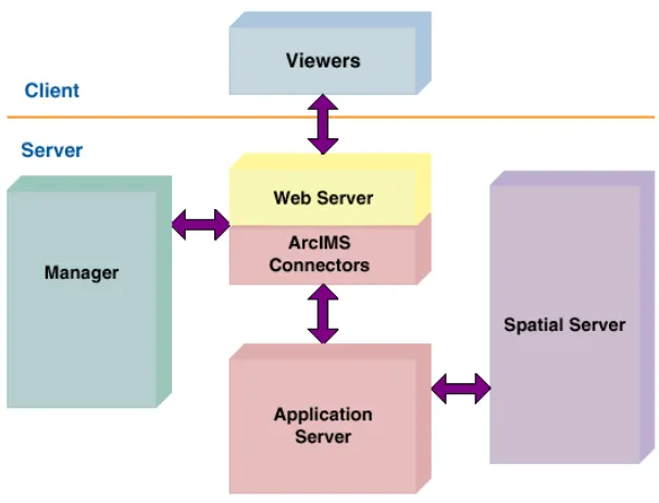
The ArcGIS system is an integrated geographic information system consisting of
three key parts [8]:
• ArcGIS Desktop Software, an integrated suite of advanced GIS
applications.
• ArcSDE gateway, an interface for managing geodatabases in a database
• ArcIMS software, internet-based GIS for distributing data and services.
ArcGIS provides a framework for implementing GIS which can be deployed on a
single desktop, or be distributed on a heterogeneous computer network of workstations
and servers. Users can deploy various parts of this system to implement a GIS of any size
– from a single-user system to large enterprise, and even societal GIS systems. It has the
architecture as shown in Figure 1.
Figure 1: The architecture of ArcGIS
2.2.2 GeoMedia—desktop GIS Software from Intergraph
GeoMedia is one of software products of Intergraph Corporation. It provides the
smart tools to capture and edit spatial data. You are able to use an industry-standard
relationships; turn information into precise, finished maps for distribution and
presentation; and put GIS data into the hands of users throughout the enterprise[9].
2.2.3 Microstation— CAD program from Bentley
Microstation is a full-featured 2-D and 3-D CAD program for MS-DOS,
Microsoft Windows, Macintosh, and Unix workstations from Bentley Systems, Inc.
created in 1984, MicroStation is a high-end package used worldwide in environments
where many designers work on large, complex projects. MicroStation Modeler is a
superset of MicroStation that provides solid modeling, and MasterPiece is MicroStation's
rendering and animation program.
The latest version of Microstation is a single, comprehensive platform for design
and engineering projects and is the foundation of the V8 Generation of software from
Bentley. MicroStation capabilities make it better suited for 3D modeling, data versatility,
workgroup productivity and application development [10].
2.3 The New Orleans District of the U.S Army Corps of Engineers
The U.S. Army Corps of Engineers (USACE) is the world's largest public
engineering agency. The New Orleans District of the USACE plans, designs, constructs,
operates and maintains federally sponsored navigation, flood control, hurricane
protection and water resources development projects in 30,000 square miles of south
central and coastal Louisiana. The district's jurisdiction includes more than 2,800 miles of
navigable waterways, 950 miles of levees and floodwalls, 12 navigation locks, six major
flood control structures, one freshwater diversion structure, and other projects to protect
in navigation channels and wetlands, and provides real estate and engineering consultant
support for other government agencies. The District helped make the ports of South
Louisiana number one in the nation in total tonnage and number one in grain exports, and
maintains 2,800 miles of navigable waterways including 400 miles of deep-draft channels
(45 feet deep from the Gulf of Mexico to Baton Rouge). The New Orleans District of
USACE operates 12 navigation locks. The District makes it possible to live and work
along the lower Mississippi River by building 950 miles of levees and floodwalls and 6
major flood control structures to protect against river and hurricane flooding. The
district's Old River Control Structure, northwest of Baton Rouge, prevents the Mississippi
from changing its course (to the Atchafalaya River Basin). It was such a diversity that has
forced the Army Corps to deploy heterogeneous GIS software suites, and motivated us to
seek a flexible architecture to integrate existing fragmented GIS components.
2.4 The data resources and software applications at the Army Corps
With so many diversified businesses, the Information Service at the New Orleans
District is supporting GIS applications, hydraulics numerical computation, spatial data
warehouse design, and spatial data integration. The data and software are used to provide
engineering management decision tools for short and long-term water resource,
navigation, and environmental projects. Currently, the internal data resources are of
various formats such as SWMM [11], UNET [12], LIDAR [13], geo-referenced images,
USGS DEM [14], HEC [15], and ASCII.
At the Army Corps, the GIS software tools are mainly COTS products made by
ESRI [16], Intergraph [17] and Bentley such as ArcInfo (ESRI’s flagship GIS toolkit for
GeoMedia Professional, Intergraph’s flagship desktop GIS tool) and Microstation
(MicroStation Version 7 and Microstation v8, Bentley’s graphically oriented applications for
Architecure/Engineering/Construction professionals). Each software suite has a substantial
number of users running the daily businesses. In addition, some small software pieces are
also used for special purposes. They were written in different languages such as Java,
JSP, C/C++, and Tcl-Tk driven VTK toolkit [18, 19]. Currently, they access geographic
information by files rather than databases.
As the data and applications have been constantly growing and diversifying,
CHAPTER 3
SYSTEM DESIGN
3.1 The Project on System Integration
Most of the work reported in this thesis is based on a research project that
supports the system integration for the New Orleans District of the U.S. Army Corps of
Engineers (USACE). The USACE district plans, designs, constructs, operates and
maintains federally sponsored navigation, flood control, hurricane protection and water
resources development projects in south central and coastal Louisiana. Engineers and
analysts have been using a myriad disparate commercial software packages to manage its
GIS and CAD projects including products of companies such as Intergraph, ESRI, and
Bentley. A team of IT workers have been working on the initiative called Enterprise GIS
(E-GIS) aims at integration of all these software programs through a centralized means of
data access.
The final goal of our project is to establish an Enterprise Geographic Information
System (EGIS) that provides various users with consistent, responsive, secured and
global views across different businesses.
This project has gone through two phases listed below:
• Phase Two: COTS GIS integrations
• Phase Three: web map services, SOAP-based web services, and
back-end server enhancement
Currently we are in Phase Three in which both proprietary and open-standard
cutting-edge technologies are involved. It turns out that this gradual chicken-little
approach has formed a systematic process toward the E-GIS’s goal.
3.2 Spatial Data Consolidation
Since the data sets are fragmented at the Army Corps, pulling out maps and data
sets from different databases or files is not automated and time consuming. As a result,
the data sets of some areas are no longer consistent. That is, the updates for the same area
spread over in multiple versions; no single version contains all the up-to-date data.
Learning from the lessons of having fragmented data sets, consolidating spatial
data was our first attempt toward the E-GIS. It helps reduce the overhead of managing
fragmented data sets, and guarantee data consistency and integrity. While consolidating
vector data sets were straightforward, doing so for raster images lacks supports from
industrial standards. I had to develop an adapter for ArcSDE server, the COTS product of
best practice, that manages raster images. In Phase One, we accomplished the
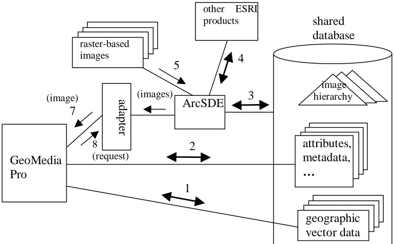
Figure 2: Spatial Data Consolidation
3.2.1 Consolidating Vector Data Sets
To store the vector data sets originally managed separately by either GeoMedia or
ArcInfo into the same Oracle Spatial database can dramatically simplify the
enterprise-wide data management. Owing to the tremendous efforts on interoperability by the Open
GIS Consortium (OGC), most of the GIS vendors have made their products compliant --
capable of accessing and manipulating data stored in the OGC spatial database standard.
Oracle Spatial Database is a leading COTS product that fully implemented OGC spatial
database standard. In our project, the Oracle spatial database has taken a pivot role in
managing vector data sets. Since the ESRI’s ArcView and Intergraph’s GeoMedia are
both used at USACE, We have to be able to store the vector data sets originally managed
by either GeoMedia or ArcInfo into the same Oracle Spatial database. This was achieved
in Phase One. Having these two COTS products accessing the shared database directly,
8 (request) (image) 7 GeoMedia Pro attributes, metadata, … image hierarchy geographic vector data shared database 1 2 a d ap te r ArcSDE raster-based images (images)
other ESRI products
the features of both COST projects such as catalog management can be leveraged to the
full extent. This can dramatically simplify the enterprise-wide data management.
Our initial experiments were very convincing. As its initial characteristics,
GeoMedia stores vector data sets in its data warehouse, a database. On the other hand,
ESRI’s products access databases through their spatial database engine, ArcSDE. By
connecting ArcSDE to GeoMedia’s warehouse database (an Oracle database), ArcView
could immediately display every map made by GeoMedia through ArcSDE without any
manual operation. Furthermore, ArcView’s catalog viewer could display every item that
GeoMedia’s catalog could display. In another experiment, we imported the vector map
files (called Shapefile) produced by ArcInfo into the Oracle database by using ArcSDE’s
importing capability. Then, with the “insert feature class metadata” command (a button
click), GeoMedia can access every piece of geographic information and feature data in
those maps, except for the high-level map descriptions.
3.2.2 Consolidating Raster Images
Traditionally, desktop GIS application tools all access images based on files.
However, as the geographic information systems grow to enterprise-wide and Internet
enabled, file-based image accessing has a number of disadvantages in supporting
geographical query processing. Especially for large images, transmitting the files often
unnecessarily slows down the response, when the user only needs to see a (small) part of
the image.
In the past, we defined a simple hierarchical structure and stored large images into
a database by partitioning the images into small blocks and recursively producing an
areas. Accessing images is optimized by fetching the right size of the image (or overview
image) with the right resolution depending on the nature of the request. For example,
loading an image with multiple megabytes would cause substantial delay. With the
hierarchies in the database, the access delay will be kept under a reasonable threshold
because a request to view any part of the same image always results in a few needed
blocks to be delivered. This approach successfully supported a GIS web view service
[22]. The advantage of doing so is the elimination of any long waiting time for loading
large image files.
ESRI’s ArcSDE stores images in the database by decomposing images into 128
by 128 pixels. The entire process of constructing the overview hierarchies is completely
automated. Viewing any part of the images does not suffer from any tangible delay. By
storing the images in the same database that hosts the vector data sets, seamless
integration between vector and raster data sets is achieved easily. This is particularly
important, because vector maps are often projected over images. ArcSDE’s database
approach to storage of images represents the best practice in the industry. However, it is
not an industrial standard. Image format standards are all based on files.
GeoMedia handles images differently. The raster-based images are brought into
GeoMedia’s data warehouse but left out from the database. While projecting vector maps
over raster-based images is well supported, no performance optimization is provided.
By consolidating images in the same database, the image data integrity problem
can be naturally solved as we did with the vector data sets. Not only does this approach
open an avenue for accessing speed improvement, it also allows us to assemble images
software tools from desktop applications to web publishing exhibit data consolidation and
optimization. We chose to consolidate the raster data into ArcSDE Sever for web
publishing and web services. I have developed an adapter that allows other software
components including GeoMedia to retrieve images of any location, of any scope with a
proper resolution level in a minimum time. The details of implementation is given in
Section 4.3.1.
3.3 Back-End Server Enhancement
It has been clear that COTS software integration is more than sharing a database.
Different COTS components need to interact with one another, often through some
adapter. When the interactions happen in a large-scale system, service requests, responses
and the service delivery components such as the adapters must be well managed. We
have chosen the J2EE server technology as the mechanism for the back-end server
management.
The JavaTM 2 Platform Enterprise Edition (J2EE) defines an industrial standard of
a software framework for developing multiple-tier enterprise applications. The J2EE
standard intends to embrace resources with a component-based application model. The
J2EE framework provides implementation of many commonly required system-level
services including the database/data resource connections pooling service, the naming
service, the transactions management, the persistence management, and the security
management. Each of these services requires significant development efforts. The
application servers that implement the J2EE standard are called J2EE application servers.
integrators. As a result, they can focus on implementing business rules. The application
business rules are encapsulated in the Enterprise Javabeans (EJBs) [20].
One of the key capabilities of J2EE application servers is connection pooling.
Establishing a connection between systems is expensive in terms of time. The connection
pool creates and then maintains a desired number of connections. The expense to
establish connections is avoided by recycling old connections for new use. The popular
Java database adapter for relational databases, JDBC, is native to J2EE application
servers. Every J2EE application server provides JDBC connections pooling service.
However, for data resources (such as a GIS) that provide high-level information (such as
area maps), the J2EE application server does not know how to manage the connections.
To solve this problem, the J2EE standard includes the J2EE Connector Architecture
specification (J2EE-CA) as a protocol for non-relational data resources to be managed by
J2EE application servers [21]. The J2EE-CA adapters are implemented in methods
dependent on the data resource software such as a GIS. By encapsulating the application
software dependency in the adapters, all the other components in the system are
independent of the data resource software; this is a common practice. The unique
advantage of the J2EE-CA is that any data resource software can fully leverage the J2EE
application servers’ system-level services by making the adapter compliant to the
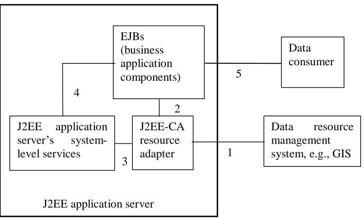
Figure 3: Interactions between the J2EE Connector Architecture components
A J2EE-CA adapter must communicate with three parties, the data resource, the
client applications, and the J2EE server shown in Figure 3 [21]. The adapter must be able
to access the data resource using the methods provided by the data resource software such
as a GIS product. Typical COTS GIS database software provides some application
programming interfaces (API). These APIs give the methods for the adapter to access the
data resource (Link 1 in Figure 3). The business applications must be able to access the
data resource through the adapter. The J2EE-CA recommends a set of optional common
client interfaces (CCI). In our implementation, we let the business applications request
data by XML messaging (Link 2 in Figure 3). These two aspects are common to all kinds
of adapters. The additional requirement for the J2EE-CA adapters is the system contracts
(Link 3 in Figure 3). The system contracts consist of three sets of Java interfaces for
connection management, transaction management, and security management. These
interfaces are not called by the client applications but by the J2EE application server. By J2EE application server
EJBs (business application components) J2EE-CA resource adapter
Data resource management system, e.g., GIS 1
2
implementing these interfaces, the adapter submits the control to the J2EE application
server. Every J2EE-CA adapter must be deployed in the J2EE application server.
Typically, adapters are accessed by the business EJBs. Link 4 in Figure 3 indicates that
all the EJBs are managed by the system-level services, too. External data consumers such
as web servlets can access the adapter through an EJB or directly (Link 5 in Figure 3).
After we succeeded in the (image) adapter, we are now ready to layout the
architecture for developing the enterprise geographic information system, in which many
other GIS applications will be able to share the database. A true enterprise geographic
information system must also be able to integrate itself into the enterprise business
information systems. This trend has been recognized by Intergraph who has responded to
this requirement in their latest GeoMedia release [24]. As described in Chapter 2, the GIS
applications at the Army Corps is so much diversified that the need for a GIS services
manager is justified. Since the Army Corps anticipates a platform-neutral, open
environment, we have chosen a J2EE application server to host the GIS services manager
shown in Figure 4. This is a high-level architecture of the Enterprise GIS. Since we want
to leverage the existing COTS products’ capacities to the full extent, the GIS services
manager does not intercept the connections between the COST components and the
database. On the other hand, the manager facilitates data accesses for the other
applications such as the SWMM analyzer and LIDAR data rendering applications
mentioned in Chapter 2. Compared to Figures 2, there are many additional components in
Figures 4.
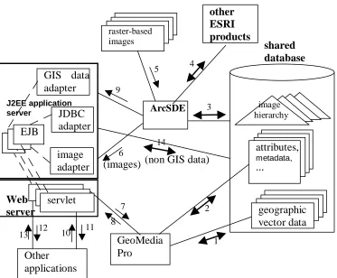
First, the “other applications” are considered in this architecture. These
types of adapters are introduced. They are the GIS data adapter that fetches data from the
ArcSDE server and the standard JDBC adapter facilitates accessing non-GIS data.
Finally, a J2EE application server along with a companion web server are utilized to
manage a set of Enterprise JavaBeans (EJB) that encapsulate the business rules, as well
as three types of adapters including the GIS data adapter, the JDBC adapter, and the
image adapter (providing the same function as the adapter in Figure 2). Since the “other
applications” vary widely, we let them access the GIS information in a very flexible
protocol, HTTP. To shield the details of the data resources, “other applications” access
the Enterprise GIS through servlets, which in turn communicate with “session enterprise
beans” [20] (represented by item “EJB” in Figure 4). The explanations for the
connections are listed in Table 1.
Specifically, the connection pooling service is particular handy for our system.
Considering the development of the Enterprise GIS, the more enrichment of the GIS
applications and web publishing, the more Army Corps’ users and outside entities will
use the system. As a result, the backend system may be overwhelmed. Experience shows
that the most fragile spots are not in the database but at the connections between the data
resources and the applications [21]. For example, even though the adapter we made in
Figure 2 works fine with a few concurrent requests, it can be overwhelmed by many
simultaneous requests long before ArcSDE is drawn. As another example, when many
current requests coming from the “other applications”, multiple JDBC connections will
Figure 4: A Sketch of the Enterprise GIS
The solution is to have a pool of connections. As described above, J2EE
application servers have built-in connections pooling capability, and the adapter must
fulfill the J2EE-CA system service contracts. We have built a J2EE-CA adapter based on
the adapter described in Section 3.2.2. Among the J2EE-CA system contracts, we have
implemented the interfaces for the connection management. Even though the other
interfaces for the transaction management and security are left blank. The adapter could
be deployed into the J2EE application server and perform. Although all the vector data
and attributes in the GIS are accessible using the JDBC adapter, this kind of low-level
operation cannot sustain possible changes in the COTS products upgrading. For instance,
the vendor can slightly change the internal database table structures in their future release image hierarchy attributes, metadata, … geographic vector data raster-based
images shared
database other
ESRI products
(images) (non GIS data)
14 6 ArcSDE 5 3 4 9 GeoMedia Pro 2 7 1 8 Web server servlet Other applications 12
13 10 11
J2EE application server
image adapter GIS data adapter
in order to improve or enhance something. Then our integration would be broken. Thus,
the “other applications” access GIS data through the GIS data adapter which in turn
connects to the ArcSDE server using the ArcSDE API. In order for these two non-JDBC
adapters to submit the control of themselves to the J2EE application server, they have to
comply with the J2EE Connector Architecture and they must reside in the J2EE
application server. As a result, GeoMedia uses the image adapter through a servlet,
servelet-Image, in HTTP.
Currently, we are in the process of prototyping this services management system
using the J2EE application server technology.
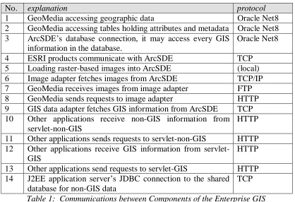
No. explanation protocol
1 GeoMedia accessing geographic data Oracle Net8 2 GeoMedia accessing tables holding attributes and metadata Oracle Net8 3 ArcSDE’s database connection, it may access every GIS
information in the database.
Oracle Net8
4 ESRI products communicate with ArcSDE TCP 5 Loading raster-based images into ArcSDE (local) 6 Image adapter fetches images from ArcSDE TCP/IP 7 GeoMedia receives images from image adapter FTP 8 GeoMedia sends requests to image adapter HTTP 9 GIS data adapter fetches GIS information from ArcSDE TCP 10 Other applications receive non-GIS information from
servlet-non-GIS
HTTP
11 Other applications sends requests to servlet-non-GIS HTTP 12 Other applications receive GIS information from
servlet-GIS
HTTP
13 Other applications send requests to servlet-GIS HTTP 14 J2EE application server’s JDBC connection to the shared
database for non-GIS data
TCP
Table 1: Communications between Components of the Enterprise GIS
3.4 Internet Map Services
The tremendous growth in Internet use has resulted in an increased demand for
the delivery of geographic data, maps, and applications over the Internet. Many leading
GIS vendors developed their web solution and add it into their GIS product family, such
as Intergraph’s GeoMedia Web Map and Esri’s ArcIMS, to meet this growing demand.
3.4.1 Create and administer Web sites using ArcIMS
To support spatial data web publish for USACE, we deplyed ArcIMS (Internet
Map Service) from ESRI product family. ArcIMS is a GIS solution which allows us to
centrally build and deliver maps, data, and tools over the Internet. ArcIMS takes
advantages of the Internet technology that makes it possible to share information and data
with many users, either locally or around the world. ArcIMS is also a flexible and
scalable tool to publish maps and develop applications based on the complexity of the
needs.
ArcIMS runs in a distributed environment and consists of both client and server
components as shown in Figure 5. The ArcIMS HTML Viewer and ArcIMS Java
Viewers are clientside components. On the server side, the ArcIMS server can provide
three different types of services. They’re Feature Service, Image Service and Metadata
Service.
The ArcIMS server can accept map request from Internet client. The IMS server
forwards the request to ArcSDE server that will in turn access the geo-spatial database
and retrieve the spatial data of interest. The spatial dataset is transmitted back to the IMS
ArcIMS provides four applications to help us create and administer web sites.
There are ArcIMS Manager, ArcIMS Author, ArcIMS Administrator, and ArcIMS
Designer. ArcIMS Manager is a Web-based application that supports the three main tasks
in ArcIMS—map authoring, Web site design, and site administration. These tasks can
also be completed using the other three applications.
Figure 5 : ArcIMS Architecture
3.4.2 Web-based spatial data search on arbitrarily organized file system
At USACE, most data are stored in the different file systems and different
computers. It is not easy for administrator to manage them. They need some approaches
for administrating the data in the file system. We developed a Web-based map search tool
for them. In this application, we take advantage of the HTML viewer of ArcIMS which is
a lightweight viewer employs JavaScript and Dynamic HTML. Java Servlet technology
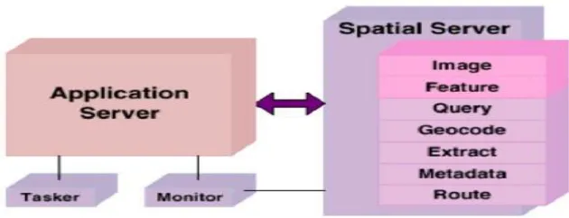
ArcIMS features largely in this approach. The ArcIMS Spatial Server is the
backbone of ArcIMS. It processes requests for maps and related information. When a
request is received, the ArcIMS Spatial Server performance one or more of these
functions shown in Figure 6:
• Image—creates image files from maps
• Feature—streams map features
• Query—searches for features matching search criteria
• Geocode—performs address-matching operations
• Extract—creates shapefiles from selected map features
• Metadata—publishes metadata
• Route—caculates routes between a set of two or more stops
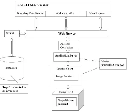
Figure 7: The architecture of web-based map search tool
The architecture of our application shows in Figure 7. The bounding coordinates
are sent to a servlet which will retrieve the data stored in database and get a list of maps
stored in the file system and located in the area we specified. The client can choose maps
from the list in HTML viewer. The viewer send the client’s request and ask ArcIMS add
the selected map onto the background as a dynamic layer. ArcIMS processes the request
and gets the information from the computer where the chosen spatial files are stored,
assembles them into the Image Service. Then retunes a new “snapshot” of map to the
3.5 SOAP-Based Web Services Framework
In the following research, we extended our previous design by introducing Web
Service technology so that MicroStation or other GIS application in a distributed
environment can also access spatial data through ArcSDE. In effect, web Services
represent a widely accepted point-to-point communication protocol that connects a pair
of computational parties shown in Figure 8 (a). For nontrivial systems, behind each web
service is a backend system that fulfills the task. In front of each web service client is
typically an application that consumes the service. This application can be as simple as a
web browser or as complex as another GIS or CAD application suite. Figure 8 (b) depicts
a conceptual structure of such a web services system. The “service consumer” and the
“web services client agent” components are in the same local area network (LAN) or
even in the same computer; they may communicate in TCP. In our experiments, we used
Java RMI. Similarly, the backend system and the web services interaction component
typically locate in the same LAN. However, between the web services provider and the
web services client, we can only assume the SOAP/HTTP protocol because different
departments and external clients are to be involved in the system.
Conceptually, the web services provide us with another mechanism to construct
distributed computing systems. Many design principles for distributed software are
applicable to the design of web services, but also are more crucial to apply to the GIS
(a) The conceptual model of web services
(b) The web services model that includes the backend and front-end
Figure 8: The web service model
Compare to general purposed web services, GIS web service requires more
careful design due to at least three factors. First, services provided by GIS system
typically requires heavy CPU utilization for complex computation. Second, GIS services
are often heavy-duty software tools that traditionally stand-alone. Third, their moving
towards the web service era is lagged. For enterprise GIS, successful communications
between components are essential but not adequate. Performance should always be a
pivot consideration in the design for GIS web services system.
This wrapper web service is going to be developed by Java language and using
SOAP message to stream the output image data. The Java web service is going to access
a DLL library using the JNI (Java Native Interface). The DLL includes the methods that
can access the spatial dataset in the database through SDE server. There are only three
methods in the DLL, one is for establishing a connection to SDE server, the other is for service processing layer service interaction layer web service provider
client interaction layer
service consumer web service client
(HTTP over the Internet) soap request/response response request backend system web services interaction component web services provider
response request web services client agent service consumer web services client
soap request/response
disconnect. The main method is the getRasterFile(), this method will be designed to
return a array of bytes to the caller. The web service will use this byte array to construct
the SOAP message.
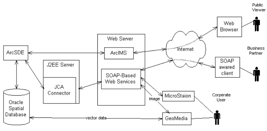
3.6 A Hybrid Web Service Architecture
Over years, the software architecture of the E-GIS has evolved into a hybrid web
service architecture shown in Figure 9. In this architecture, the essential principle is to
consolidate all spatial data sets into a shared spatial database (an Oralce database in
particular). Enhanced by the ArcSDE Server, the raster images can also be stored in and
managed by the database. Our adapter allows us to connect the ArcSDE server to web
Service clients, in the standard SOAP protocol. By accommodating both the COTS
Internet Map Service software ArcIMS and SOAP-based web services in the web server,
we have not only full leveraged the features of ArcIMS, but also supplemented the COTS
with more flexible web service provider components. They can be used by both external
business partners and the other software tools that are not capable of accessing OGC
standard spatial data or ArcSDE images. When these web services are popular, the
management of the back-end server software must be scalable. Therefore, we have
introduced the J2EE server into the architecture in order to enhance the back-end service
performance. We believe this hybrid architecture can endorse performance, scalability
CHAPTER 4
IMPLEMENTATION
Our approach to enterprise GIS system is to put spatial data into a centralized
database system and make the dataset sharable across heterogeneous GIS desktop
software. We have implemented the vector data integration using Oracle spatial
technology. In our system, the raster data sets are also saved in the Oracle database. ESRI
Company provides raster data import and export functions to its own desktop software. In
order to support raster dataset sharing for non-ESRI client, we developed an adapter that
conveys the raster dataset import and export functionality of ArcSDE server in a set of
interfaces for external components. The adapter was developed using C language and
encapsulated into dynamic link library package for deployment in windows system. The
client software can invoke the functions through any programming environment that
recognizes DLL packages. In our implementation, the DLL package was developed
mainly for calls from VB and Java language, the most common used development
4.1 Technologies Review
4.1.1 ArcSDE Server and development API
ESRI enterprise GIS solution is based on a centralized geo-spatial database. To
facilitate spatial data sharing and management, the solution include SDE (Spatial Data
Engine) server that acts as an application server. SDE server is responsible for receiving
the spatial data request and serving the client request with spatial data accordingly. SDE
server also maintains the data integrity, manage the transaction and tune the overall
performance of the spatial data service. The ArcSDE server also provides a set of API for
customized application development. ArcSDE contains two main application
programmer interfaces for developers to build applications that work with and query
information contained in multi-user geo-databases: ArcSDE Client API for C
programmers and ArcSDE Client API for Java programmers. These APIs provide GIS
functions for advanced application development. ArcSDE works as an application server,
delivering spatial data to many kinds of applications or even serving spatial data across
the Internet.
4.1.2 ArcSDE raster adapter and JNI
ArcSDE raster adapter is developed in the EGIS system to support non-ESRI GIS
application to access and query raster-based spatial information served by the ArcSDE
server. We choose to use the ArcSDE high-level C API for the development based on two
facts. First, at the time of our development, ESRI hadn’t release a full Java version API
for the ArcSDE server, in order to take advantage of the raster data manipulation, we
native language of the ArcSDE server application that can achieve the best performance
leverage the full capacity of ArcSDE server.
The raster adapter developed by C API is compiled into dynamic linked library in
windows system for deployment. The raster adapter DLL package consists of generic
subroutine for interacting with the ArcSDE server as well as application specific
functions. Since, we are going to integrate the raster adapter into our EGIS based on
J2EE framework, we need to address the issue of connecting the J2EE framework with
ArcSDE server.
The Java Native Interface technology is employed for the interaction between the
J2EE framework and ArcSDE server. The JNI comes with the standard Java
Development Kit (JDK) from Sun Microsystems. It permits Java programmers to
integrate native code (currently C and C++) into their Java applications.
4.1.3 TIFF LIB and GEOTIFF LIB
Tag Image File Format (TIFF) is a widely used format for storing image data.
TIFF LIB is a set of C functions (a library) that support the manipulation of TIFF image
files. The library requires an ANSI C compilation environment for building and presumes
an ANSI C environment for use. Our ArcSDE raster adapter needs TIFF LIB to help
generate TIFF image file as the output data format which can be consumed by non-ESRI
client.
TIFF file is the mostly supported image format for GIS purpose. In most cases,
geographical information is added to the TIFF to form so called geo-TIFF file. This kind
used to identify the coordinate system and location of the raster file. This is why the
GEOTIFF LIB is employed to geo-reference a TIFF file.
4.1.4 Web services
A web service is a software component that can be accessed over the Internet for
use in other application. Their application field can be wide. They are used in e-business,
Geographical Information System, and many other application areas. Specifically, web
services are a stack of emerging standards that describe a service-oriented,
component-based application architecture.
The main interest of web services is that they can be accessed programmatically
by HTTP protocol. Unlike web sites and desktop applications, web services are not
designed for direct human interaction, and they do not have a graphical user interface.
Rather, web services operate at the code level; they are called by and exchange data with
other software. Web services can be incorporated into software designed for human
interaction.
For example, GIS web services offer a way for developers to include GIS content
and capabilities in their application without having to host the data. The result is
significant savings of development time, expense and computer resources.
By web services, we mean XML web services, the software services exposed on
the web through SOAP. SOAP is an XML-based communication protocol and encoding
format for inter-application communication. Originally conceived by Microsoft and
Userland software, it has evolved through several generations and the current spec, SOAP
1.1, is fast growing in popularity and usage. The W3C’s XML protocol working group is
released a working draft of SOAP 1.2, which cleans up some of the more confusing areas
of 1.1 spec. SOAP is widely viewed as the backbone to a new generation of
cross-platform cross-language distributed computing applications, the web services.
4.1.5 ArcIMS and ArcXML
To support spatial data web publish, ESRI product family also include an IMS
(Internet Map Service) server. The IMS server can accept map request from Internet
client. The IMS server forwards the request to ArcSDE server that will in turn access the
geo-spatial database and retrieve the spatial data of interest. The spatial dataset is
transmitted back to the IMS server in a reverse direction and the IMS server will serve
the client with a map.
The ArcIMS server itself has a built-in map request language based on XML
called ArcXML (The Arc Extensible Markup Language). ArcXML file format provides a
structured method for communication between all ArcIMS components. It defines
content for ArcIMS services and is used for requests and responses between clients, the
business logic tier and servers.
4.2 Use of the Shared Spatial Database
To achieve the vector data sharing for GeoMedia, we employed Oracle Spatial
technology shown as Figure 10. Oracle spatial is a well-defined, object-oriented industry
standard on vector-based data storage and is supported by most GIS vendor. Both ESRI
and Intergraph give support to Oracle Spatial technology. Arcinfo and Geomedia can
both directly access the vector data that stored in Oracle spatial. Oracle spatial is the
Figure 10: Vector Data sharing for GeoMedia
Database accessing performance has been one of our concerns. More specifically,
our concern is about the impact of crossing accesses. That is, one GIS tool accesses the
data imported by another one. Both Geomedia and ArcSDE create spatial index when
they import vector data sets into the Oracle database. ArcSDE also provides several
options for spatial index creations that can be specified by the users. Different spatial
index methods may affect the spatial data query performance. In an initial evaluation, we
used ArcMap to query vector data through the ArcSDE server from the Oracle database,
and compared the response time of accessing the “native data sets” (imported by
ArcSDE) and that of accessing the “foreign data sets” (imported by GeoMedia) as shown
in Table 2. In testing, the query for every data set was to load the entire layer. No
significant performance penalty to the foreign data sets was observed. This confirms the
feasibility of our data consolidation plan. We also realized that the initial test was
indexes. Additionally, ArcSDE has a comprehensive performance tuning guide.
Therefore, further studies on the impact of crossing accesses to query performance are
needed.
Data set name Geometry type
Features Count
Imported by ArcSDE (second)
Imported by Geomedia (second)
Barge Multipoint 778 2 2
Powerlines Polyline 9226 3 3
PrimaryRoad Polyline 1633 3.5 4
Aquifer Polygon 2388 11 13
Geometry storage type: Oracle Spatial Object Model Spatial Index: true
Open connection delay: 3 seconds
Table 2: Accessing time comparison between native and foreign data sets
4.3 ArcSDE Adapters: Raster Adapter and Vector Adapter
4.3.1 ArcSDE Raster Adapter
We developed software component to support raster data retrieval from ArcSDE
server. ESRI Company provides raster data import and export functions to its own
desktop software. In order to support the raster data sharing for non-ESRI client, we
have to develop a middleware. This middle-ware is to wrap the raster dataset import and
export functionality and provide a set of interfaces for them. This middleware is called
“ArcSDE Raster Adapter”.
The adapter is developed using C language and encapsulate into DLL package
for deployment. The client software could take advantage of the DLL by invoking the
functions through any programming environment that could manipulate DLL package.
Here the DLL package is developed mainly for call from VB language. It can also be
As shown in Figure 11, the Geomedia desktop software sends request through the
adapter. SDE adapter will first make connection to the oracle server through SDE server
and export the raster data into a Tiff file according to the given bounding coordinates.
There are two issues must be addressed for the raster adapter. One is that we need to add
geographic information to the tiff file to generate geo-tiff file. The other is the resolution
control problem. To enhance display performance, the ArcSDE server has built pyramid
for raster dataset. Given bounding coordinate, we can return the required image data with
different resolution to suit to the user’s display resolution.
Figure 11: Raster data sharing for GeoMedia
4.3.1.1 Coordinate System
A coordinate system (CS) defines the location of a point on a planar or spherical
is difficult to change to a new coordinate system. Changing coordinate systems is
required when integrating data from different sources into a common coordinate system.
A geographic coordinate system is a three–dimensional reference system that
locates points on the Earth’s surface. The unit of measure is usually decimal degrees. A
point has two coordinate values: latitude and longitude. Latitude and longitude measure
angles. Even though geographic coordinates are angular units, ArcSDE stores and treats
them as if they are planar. In this case, longitude values are considered the x-coordinate,
while latitude values are the y-coordinate.
A projected coordinate system is a two-dimensional planar surface. However, the
Earth’s surface is three-dimensional. Transforming three-dimensional space onto a
two-dimensional surface is called projection. Projection formulas are mathematical
expressions that convert data from a geographical location (latitude and longitude) on a
sphere or spheroid to a corresponding location (x and y) on a flat, two–dimensional
surface.
In order to display the geographical information on a monitor of computer, the
spatial object are represented as simple or complex geometries and displayed on the
computer monitor. Thus, we also need to introduce a raster space coordinate system to
help define how a geographical CS or Projection CS are mapping to the computer output
devices.
The Figure 12 below shows the relationship of the three coordinate systems:
• Raster Space CS: Raster space Coordinate System which unit is pixel
• Projection CS: Projection Coordinate System which unit is meter or foot
Meter (foot)
Meter (foot) Projection CS
Latitude (degree)
Longitude (degree) Geo world CS
Raster workspace CS
pixel
pixel
Figure 12: the relationship of the three coordinate systems
4.3.1.2 Resolution level
ArcSDE populates the raster blocks table according to a declining resolution
pyramid. The height of the pyramid is determined by the number of levels specified by
application. The application such as ArcToolbox or ArcCatalog may allow you to define
the levels or it may request that ArcSDE calculate them, or it may offer both possible
choices.
The pyramid begins at the base, or level 0 which contains the original pixels of
the image. The pyramid proceeds toward the apex by coalescing four pixels from the
previous level into a single pixel at the current level. This process continues until less
than four pixels remain or until ArcSDE exhausts the defined number of levels.
The additional levels of the pyramid increase the number of raster block table rows by
one third. However, since it is possible for the user to specify the number of levels, the
true apex of the pyramid may not be obtained, limiting the number of records added to
the raster blocks table.
Figure 13: Raster pyramid in ArcSDE
When you build a pyramid, more rasters are created by progressively
downsampling the previous level by a factor of two until the apex. As the application
zooms out and the raster cells grow smaller than the resolution threshold, ArcSDE selects
a higher level of the pyramid. The purpose of the pyramid is to optimize display
performance.
The pyramid allows ArcSDE to provide the application with a constant resolution
of pixel data regardless of the rendering window's scale. Data of a large raster transfers
quicker to the client when a pyramid exists, since ArcSDE can transfer fewer cells of a
reduced resolution.
In our raster adapter, we provide the users a functionality to choose the resolution
level by themselves or automatically by the adapter shown in Figure 14. In order to
internal method called getLevel in our raster adapter. We use the following formula to
calculate the level we will select:
)] / ( log ), / (
max[log2 lc ls 2 wc ws
level=
lc, length of the selected clip
ls , length of the screen resolution
wc, width of the selected clip
ws , width of the screen resolution
Figure 14: select resolution level in raster adapter
4.3.1.3 Functions provided by the C DLL
We have developed two version of raster adapter. One version is designed to
return a single tile each time for end user’s request. This solution has more advantages
over the other version in that it provides more flexibility and achieves high performance