Available online at www.ijiere.com
International Journal of Innovative and Emerging
Research in Engineering
e-ISSN: 2394 – 3343 p-ISSN: 2394 – 5494
AUTOMATED FURROW RIDGER
BALAJI V, GOWTHAM P, HARIPRASAD T, MUTHU YUVARAJ S, NITHYAPRIYA S
ABSTRACT:
In agricultural field the furrows are covered manually or by animal operated plankers. Thus, the process is very much time consuming and labour intensive in this project the furrows are ploughed automatically. As a soil conservation tillage method, ridged-furrow has been extended to apply in sloping field. Since the ridge can stop erosion of soil, the effect of soil conservation is obviously. Based on ridged-furrow can form soil reservoirs and increase soil moisture to save and increase water, the article has developed a new design method as a reference for tillage in semi-arid sloping field.
Keywords : animal operated plankers, soil conservation tillage method
INTRODUCTION
In agricultural field the furrows are covered manually or by animal operated plankers. Thus, the process is very much time consuming and labour intensive.in this project the furrows are ploughed automatically. The ridged-furrow tillage is furrows along the land slope and plus lateral ridges forming holes to remain soil erosion and runoff. Owing to soil and water erosion is very serious in hilly area of Heilongjiang province, soil conservation is very important. Before, ridged-furrow tillage was mainly used for protecting sloping farmland and conserving soil erosion, literature researches more concentrated to the effect of soil erosion, but less research the effect of saving water. Through the field test, the saving water effect of ridged-furrows and the adaptability for sloping land saving-water agriculture in semi-arid region have been tested and numerical analysis and design results have been obtained. The article propounded a new design method of ridged-furrow, which is applicable for the local conditions as the basic study on the technology of ridged-furrow application.
INTRODUCTION
DESIGN CALCULATION
The ridged-furrow tillage is furrows along the land slope and plus lateral ridges forming holes to remain soil erosion and runoff. Owing to soil and water erosion is very serious in hilly area of Heilongjiang province, soil conservation is very important. Before, ridged-furrow tillage was mainly used for protecting sloping farmland and conserving soil erosion, literature researches more concentrated to the effect of soil erosion, but less research the effect of saving water. Through the field test, the saving water effect of ridged-furrows and the adaptability for sloping land saving- water agriculture in semi-arid region have been tested and numerical analysis and design results have been obtained. The article propounded a new design method of ridged-furrow, which is applicable for the local conditions as the basic study on the technology of ridged-furrow application.
CALCULATION OF TORQUE
Mass of the objects
Mass of Plough = Volume * Density
= 679.348 * 2.71
= 1834 g
Mass of Frame = Volume * Density
= 1.329*2.71
= 3587 g
Total mass of chassis = 1.834+3.587
= 5422 g
Total weight of Vehicle
Total weight of chassis = 5422 g
Weight of batteries = 4000 g
Weight of wheels = 800 g
Weight of remaining
materials = 2600 g
Total weight of Vehicle ≈ 13000 g
Materials
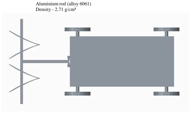
Aluminium rod (alloy 6061) Density - 2.71 g/cm³
Fig 3.2 Top view of furrow ridger
EXTERNAL FORCE ACTING ON PLOUGH
Soil Density = 1600 g/m³
= 0.0005m³
Mass =Density*Volume
= 1.6*0.0005
Mass =0.0008 kg
= 0.8g
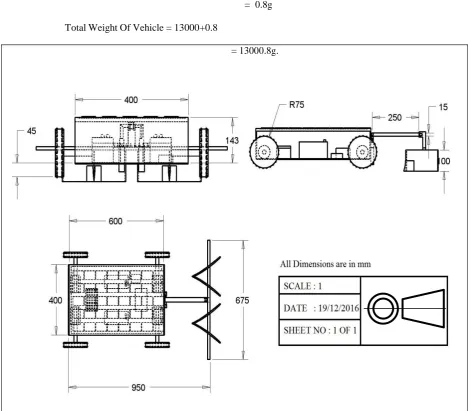
Total Weight Of Vehicle = 13000+0.8
= 13000.8g.
Fig 3.3 2-D Drawing of furrow ridger
Force acting on the vehicle
F = ma F = 13*9.8
= 127.4 N
Torque of the vehicle
T = F l sinθ
T = 127.4*0.95 (since θ=90º) T = 121.03 Nm
Assumed velocity of the ridger = 2.5m/s
Power = Force * Velocity
= 127.4 * 2.5
DESIGN OF BALL BEARING
Outer Diameter of Bearing (D) = 47 mm
Thickness of Bearing (B) = 14 mm
Inner Diameter of the Bearing (d) = 25 mm
r₁ = Corner radii on shaft and housing r₁ = 1 (From design data book) Maximum Speed = 14,000 rpm (From design data book) Mean Diameter (dm) = (D + d) / 2
= (47 + 25) / 2 dm = 36 mm Spring index (C) = (D /d)
= 12 / 2
C = 6
WALL STRESS FACTOR
Ks = 4C – 1 + 0.65
4C – 4 C
= (4 X 6) -1 + 0.65
(4 X 6)-4 6
Ks = 1.258
DESIGN CONCEPT CAD/CAE
Computer aided design or CAD has very broad meaning and can be defined as the use of computers in creation, modification, analysis and optimization of a design. CAE (Computer Aided Engineering) is referred to computers in engineering analysis like stress/strain, heat transfer, and flow analysis. CAD/CAE is said to have more potential to radically increase productivity than any development since electricity. CAD/CAE builds quality form concept to final product. Instead of bringing in quality control during the final inspection it helps to develop a process in which quality is there through the life cycle of the product. CAD/CAE can eliminate the need for prototypes. But it required prototypes can be used to confirm rather predict performance and other chara cteristics. CAD/CAE is employed in numerous industries like manufacturing, automotive, aerospace, casting, mould making, plastic, electronics and other general-purpose industries. CAD/CAE systems can be broadly divided into low end, mid end and high-end systems. Low-end systems are those systems which do only 2D modeling and with only little 3D modeling capabilities. According to industry static’s 70-80% of all mechanical designers still uses 2D CAD applications. This may be mainly due to the high cost of high-end systems and a lack of expertise. Mid-end systems are actually similar high-end systems with all their design capabilities with the difference that they are offered at much lower prices. 3D sold modeling on the PC is burgeoning because of many reasons like affordable and powerful hardware, strong sound software that offers windows case of use shortened design and production cycles and smooth integration with downstream application. More and more designers and engineers are shifting to mid end system. High-end CAD/CAE software’s are for the complete modeling, analysis and manufacturing of products. High -end systems can be visualized as the brain of concurrent engineering. The design and development of products, which took years in the past to complete, is now made in days with the help of high-end CAD/CAE systems and concurrent engineering.
CREO
is used by discrete manufacturers for mechanical engineering, design and manufacturing. Created by Dr. Samuel P. Geisberg in the mid-1980s, Pro/ENGINEER was the industry's first successful rule-based constraint (sometimes called "parametric" or "variational") 3D CAD modeling system. The parametric modelling approach uses parameters, dimensions, features, and relationships to capture intended product behaviour and create a recipe which enables design automation and the optimization of design and product development processes.
CONCLUSION
This design approach is used by companies whose product strategy is family-based or platform-driven, where a prescriptive design strategy is fundamental to the success of the design process by embedding engineering constraints and relationships to quickly optimize the design, or where the resulting geometry may be complex or based upon equations. Creo Elements/Pro provides a complete set of design, analysis and manufacturing capabilities on one, integral, scalable platform. These required capabilities include Solid Modeling, Surfacing, Rendering, Data Interoperability, Routed Systems Design, Simulation, Tolerance Analysis, and NC and Tooling Design. Like any software it is continually being developed to include new functionality. The details below aim to outline the scope of capabilities to give an overview rather than giving specific details on the individual functionality of the product.
COMPONENTS AND DESCRIPTION INTRODUCTION
The ridged-furrow tillage is furrows along the land slope and plus lateral ridges forming holes to remain soil erosion and runoff. Owing to soil and water erosion is very serious in hilly area of Heilongjiang province, soil conservation is very important. Before, ridged-furrow tillage was mainly used for protecting sloping farmland and conserving soil erosion, literature researches more concentrated to the effect of soil erosion, but less research the effect of saving water. Through the field test, the saving water effect of ridged-furrows and the adaptability for sloping land saving- water agriculture in semi-arid region have been tested and numerical analysis and design results have been obtained. The article propounded a new design method of ridged-furrow, which is applicable for the local conditions as the basic study on the technology of ridged-furrow application.
LIST OF COMPONENTS
1.Wheel 2.Servo motor 3.Battery 4.Control unit 5.Frame 6.Bearings
FRAME
This is made of mild steel material. The whole parts are mounted on this frame structure with the suitable arrangement. Boring of bearing sizes and open bores done in one setting so as to align the bearings properly while assembling. Provisions are made to cover the bearings with grease.
WHEEL ARRANGEMENT
The simple wheel and braking arrangement is fixed to the frame stand. This wheel arrangement is setup for showing the successful working of our project. But the real implementation can be done in the automobile and the brakes can be applied to all the four wheels. For conducting load tests, suitable brake drum and the belt are provided.
SERVOMOTOR
An electric motor is a machine which converts electrical energy to mechanical energy. Its action is based on the principle that when a current-carrying conductor is placed in a magnetic field, it experiences a magnetic force whose direction is given by Fleming’s left hand rule.
When a motor is in operation, it develops torque. This torque can produce mechanical rotation. DC motors are also like generators classified into shunt wound or series wound or compound wound motors.
MICROCONTROLLER UNIT
INTRODUCTION ABOUT MICROPROCESSOR:
It does not mean that any micro controller should have above said features on-chip. Depending on the need and area of application for which it is designed, the on-chip features present in it may or may not include all the individual sections said above. Any micro computer system requires memory to store a sequence of instructions making up a program, parallel port or serial port for communicating with an external system, timer/counter for control purposes like generating time delays, baud rate for the serial port, apart from the controlling unit called the Central Processing Unit.
CONTROL UNIT
In automotive electronics, ElectronicControlUnit (ECU) is a generic term for any embedded system that controls one or more of the electrical system or subsystems in a motor vehicle.
Types of ECU include Electronic/engine Control Module (ECM), Power train Control Module (PCM), Transmission Control Module (TCM), Brake Control Module (BCM or EBCM), Central Control Module (CCM), Central Timing Module (CTM), General Electronic Module (GEM), Body Control Module (BCM), Suspension Control Module (SCM), control unit, or control module. Taken together, these systems are sometimes referred to as the car's computer. Technically there is no single computer but multiple ones. Sometimes one assembly incorporates several of the individual control modules.
CONCLUSION
Some modern motor vehicles have up to 80 ECUs. Embedded software in ECUs continues to increase in line count, complexity, and sophistication. Managing the increasing complexity and number of ECUs in a vehicle has become a key challenge for original equipment manufacturers (OEMs).
In our project we use the control unit for controlling the DC motor that activates/deactivates the vehicle braking system. It is very simple in operation that, when the brake lock system is activated from the remote, the control unit switches on the motor and when it is deactivated from the remote, then the control unit reverses the motor direction.
CONCLUSIONS
Thus this project work is much useful in all Automobile industries. For practical applications this is fabricated for light duty. Its height, weight and other mechanical designs are not suitable for any other heavy work or work on hardened material.In conclusion remarks of our project work, let us add a few more lines about our impression project work. Thus we have developed an “AUTOMATED FURROW RIDGER” which helps to agriculture uses. So for in future the same project will be remolded and designed to carry out multi functional operation.
ACKNOWLEDGMENT
At this pleasing moment of having successfully completed my project, I wish to convey my sincere thanks and gratitude to the management of my college who provided all the facilities to
me.
I would like to express my sincere thanks to my principal Dr. J.Janet for forwarding me to do my project and offering adequate duration in completing my project.
I am also grateful to the Head of Department Dr.P.Balamurugan for his constructive suggestions and encouragement during my project. With deep sense of gratitude, I extend my earnest and sincere thanks to my guide Assistant Professor. Ms.S.NithyaPriya, Department of Mechatronics Engineering for his kind guidance and encouragement during this project. I also express my indebt thanks to all teaching staff of Mechatronics Engineering Department. I also extend my sincere gratitude to mechanical laboratory technicians for their kind help to carry out the machining operations.
We also wish to express our sincere gratitude to Dr. T. A. Selvan, Department of Mechatronics Engineering for his constructive suggestions and encouragement to do our project. We would like to thank all other faculty members as well as non-teaching staff of the Department of Mechatronics Engineering for their patient help throughout the project.
REFERENCES
[1] R. R. Price, R. M. Johnson, R. P. Viator, J. Larsen, A. Peters, Fiber Optic Yield Monitor For A Saccharumofficinarum Harvester, American Society of Agricultural and Biological Engineers, Vol. 54
[2] Vaibhav V. Randive et al. Design and Fabrication of Multipurpose Machine for Saccharumofficinarum Planting 306| MIT College of Engineering, Pune, India, AMET 2016, INPRESSCO IJCET Special Issue-4 (March 2016) H.A.
[3] Abd, El Mawla, B. Hemida, W.A. Mahmoud,( 2014), Study On The Mechanization Of Saccharumofficinarum Transplanting, International Journal of Engineering and Technical Research, Volume-2,
[4] Umesh S. Patkar, Rajesh W. Lanjewar, (2007), A Tractor Driven Mechanism For Uniform Planting Of Saccharumofficinarum , 13th National Conference on Mechanisms and Machines, December 12-13,
[5] Holsambre D.G. (1997), Irrigation Management Techniques, Saccharumofficinarum Farming Systems Journal of IWRS, Vol.17 (3) No: 1.pp 1-10.
[6] Dr.R.L.Yadav (2007), Vision-2025, Indian Institute of Saccharumofficinarum Research, Lucknow. 62 p. [7] Dafa’alla, A.M. and M.A.Hummeida, (1991), Performance evaluation of Saccharumofficinarum planter, J. King