DYNAMICAL QUALITY IMPROVEMENT OF MECHATRONIC SERVO
SYSTEM USING VARIABLE STRUCTURE VELOCITY CONTROLLER
Vilius Antanas Geleževi
č
ius
Department of Control Technology, Kaunas University of Technology Studentu Str. 48, LT–51367 Kaunas, Lithuania
e-mail: [email protected]
Nerijus Šul
č
ius
Department of Electrical engineering, Šiauliai University
Vilniaus St. 141, LT – 76353 Šiauliai, Lithuania
Abstract. A technique of dynamical quality improvement of the mechatronic servo system is presented in the article. Application of variable structure velocity controller, whose control law during the transient regime of the system can be automatically changed from the proportional-integrating (PI) to the proportional (P) law and vice versa, is the core of this technique. Two methods based on fuzzy logic and preprogrammed "Lookup Table" application, ensuring automatic change of velocity controller structure, are proposed and investigated. The simulation results of the servo system confirming suitability of the proposed dynamical quality improvement technique are presented and discussed.
Keywords: velocity control, dynamical quality, servo system, variable structure controller, fuzzy logic.
1. Introduction
The cascade control of the mechatronic servo drive ensuring the quantitative or the symmetrical optimum condition [1] is still widely used. The velocity control system of the mechatronic servo drive consists of the internal torque (current) control loop adjusted in ac-cordance with the quantitative optimum condition and external velocity control loop adjusted according to the quantitative or to the symmetrical optimum con-ditions. The quantitative optimum condition requires the proportional (P) velocity controller and ensures optimum rapidity response to the step mode reference signal. However such a control mode distinguishes by a steady-state velocity error caused by the external load of the motor. In order to avoid a steady-state velocity error caused by this disturbance, the propor-tional-integrating (PI) velocity controller can be used. Usually, such a controller is adjusted according to the symmetrical optimum condition [1 2, 3]. However, the use of the PI controller declines the dynamical quality of the mechatronic servo system.
In order to coordinate the advantages and eliminate disadvantages of both the quantitative and the sym-metrical optimum control methods, the variable struc-ture velocity controller has been proposed [4]. The main peculiarity of such a controller is the possibility of automatic change of its control law from the
proportional-integrating (PI) mode to the proportional (P) mode and vice versa during the transient regime of the servo drive. Two different methods of the velocity controller control law automatic change are proposed and investigated in [5]. The dynamical quality of the system regime has been evaluated with the help of the ITAE (Integral of Time multiplied by Absolute Error) quality criterion. Supposing that the best dynamical quality of the system corresponds to the minimum value of this criterion, the specific parameters of ve-locity controller structure switching from one control law to another have been defined.
first method is based on the fuzzy logic methodology and the second one – on the preprogrammed "Lookup Table" application; both of them allow defining of necessary P control law duration in dependence of the static load level. The problem arises with the static load level definition. On purpose of acting load of servo drive estimation, the Luenberger observer is proposed. The results of investigation of the mecha-tronic servo system with variable structure velocity controller guided by Luenberger observer are presen-ted in this article.
2. Discussion of mechatronic servo system with velocity controller of variable structure
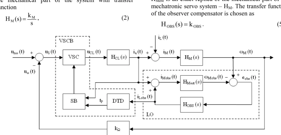
The block diagram of the mechatronic servo system with velocity controller of variable structure is presented in Figure 1. The mechatronic servo system consists of the internal motor current control loop represented by the simplified transfer function
1 s 2T
k (s) H
c
CL
CL = ⋅ + , (1)
the mechanical part of the system with transfer function
s k (s)
H M
M = , (2)
a velocity feedback – kΩ, the Luenberger observer
block – LO and the variable structure velocity cont-roller block– VSCB. The main parts of the VSCB are the variable structure controller VSC itself, which is able to turn proportional (P) control law
PΩ P(s) k
H = , (3)
to proportional-integrating (PI) control law
) s 8T
1 (1 k (s) H
c
PΩ
PI = + ⋅ , (4)
and vice versa, the control law switching block – SB, and the P control law delay time definition device – DTD(based on the fuzzy logic methodology or on the preprogrammed "Lookup Table" application). In the equations (1)– (4) the following notations are used: kPΩis a gain of the proportional (P) velocity controller,
kCL– a gain of the closed current control loop, kM– a
gain of the mechanical part of the system, Tc – a small
time constant of the power converter.
Due to the static load level estimation of the servo drive, the Luenberger observer [6] has been developed and implemented. The structure of the observer in the form of the block LO is presented in Fig. 1, where HMest is an exact replica of the mechanical part of the
mechatronic servo system – HM. The transfer function
of the observer compensator is chosen as
OBS OBS(s) k
H = . (5)
Figure 1. Block diagram of the mechatronic servo system with variable structure velocity controller block VSCB
and Luenberger observer block LO
The response curve of observer provoked by the evaluated load step mode change is presented in Fig. 2. The curve named Act is the actual (settled) step mode nominal static load current. The curve named Obs is the estimated static load current obtained from the output of the developed Luenberger observer. It is seen that the evaluated value of the observed static load current asymptotically converges to the value of the actual (settled) nominal static load current. It is obvious from Figure 2 that the convergence time is shorter than the PI-P control law switching time (vertical STline), thus the observed static load current obtains steady-state value (equal to the actual (settled) value) before the time when control law of the controller id to be switched from PI to P mode.
Consequently, the derived static load current signal is suitable for passing from the Luenberger observer to the P control law delay time definition device.
3. Design of device for P control law delay time definition
device to the output: fuzzification, implication, aggre-gation and defuzzification.
0 0.005 0.01 0.015 0.02 0.025 0 0.2 0.4 0.6 0.8 1 1.2 1.4 1.6 1.8 2 ST Act Obs
t, s iN
Figure 2. Curves illustrating static load estimation process
Figure 3. Architecture of the fuzy logic device
During the first stage – fuzzification, the input sig-nal – the observed static load current value is taken and the degree to which it belongs to the appropriate membership functions is determined (Figure 4). Infe-rence engine performs implication and aggregation functions and determines the aggregated fuzzy output in the dependence on the linguistic rules from the Rule base. The Rule base has been formed manually according to the investigation results [7] and consists of six IF-THEN linguistic rules :
⎪ ⎪ ⎪ ⎪ ⎩ ⎪⎪ ⎪ ⎪ ⎨ ⎧ Short; Very is THEN Nominal is IF Short, is THEN Medium is IF Medium, is THEN Medium Very is IF Long, is THEN Small is IF Longer, is THEN Small Very is IF Longest, is THEN None is IF Delay Load Delay Load Delay Load Delay Load Delay Load Delay Load (6)
where Load is an input linguistic variable– the obser-ved static load current iLobs with the range [0 ÷ iNobs],
iNobs – the observed nominal static load current; Delay
is an output linguistic variable – the proportional (P) control law duration time tP with the range [0.01 ÷
18.5 ms].
Six linguistic values – appropriate membership functions have been formed manually and assigned to the input and output linguistic variables (Figure 4).
It has been chosen product implication method, which scales the fuzzy set. Modified fuzzy sets of each rule are then aggregated into a single output fuzzy set. Finally, the resulting set is defuzzified (solved) to a single (crisp) value – the proportional (P) control law duration time tP. Two types of the fuzzy logic device
(FLD) have been designed: Mamdani-type and Su-geno-type [7]. In the Mamdani-type FLD, after the aggregation process, the output membership function of the output variable (Fig. 4) is a fuzzy set. While a Sugeno-type FLD uses a constant value (singleton) as the output membership function (in our case it has six constant values (singletons): 0.01, 1.2, 3.0, 7.0, 13.0, 17.0 ms). In order to obtain a crisp output value – the P control law duration time, the center of gravity defuzzification method has been chosen in the Mamdani-type FLD while the weighted average me-thod has been selected in the Sugeno-type FLD.
The input-output dependence of the delay time definition device – the tP = f (IR) = f (IL/IN) diagram is
presented in Figure 5, where tP – the duration time of
the proportional (P) control law, IL – the settled load
current value, IN – the nominal load current value, IR –
the relative load current value (the ratio of IL and IN
currents). The Opt curve (Figure 5) is obtained from the investigation results reported in [5] and demonstrates optimal tP = f (IR) dependence. The SISO
delay time definition device with the implemented optimal tP = f (IR) dependence ensures the best
dy-namical quality (defined by the ITAE quality criterion) of the mechatronic servo system. The deviation of the duration time (tP) from the optimal values (Opt curve)
causes the decline of the dynamical quality of the mechatronic servo system. The quality region QR of the duration time (tP) change is defined (Figure 5,
un-lined zone). Within the QR, the dynamical quality of the mechatronic servo system decreases up to 5% compared to the best dynamical quality. Nevertheless this possible decrease of the dynamical quality due to the duration time (tP) change is considered as
acceptable. Two curves have been derived from the fuzzy logic device and are presented in Fig. 5: M curve has been obtained from the designed Mamdani-type FLD, S curve has been obtained from the de-signed Sugeno-type FLD. The obtained M and S curves are located within the quality region QR(Fig. 5) and coincide with Opt curve in the range [0.5 ÷ 1] of the IR, but differ a little from Opt curve in the range
[0 ÷ 0.5) of the IR. Consequently, both Mamdani-type
and Sugeno-type fuzzy logic devices are suitable to use for the definition of the P control law duration time.
Programmable delay time definition device. The secondP control law delay time definition method is based on the preprogrammed "Lookup Table" appli-cation. The programmable SISO delay time definition device has been built in the form of the "Lookup Table": the input variable – the load current value (obtained from the Luenberger observer) is mapped to the corresponding output variable – the duration time
iLob Inference engine: tP
of the proportional (P) control law. Considering the defined quality region QR (Fig. 5), the input-output dependence of the programmable device – tP = f (IR)
curve (named Progr in Fig. 5) is defined and described by two linear functions:
⎩ ⎨ ⎧
≤ ≤
< ≤ ⋅
− =
. 1 I 0.5 if , 0.00001
, 0.5 I 0 if , I 0402 . 0 0201 . 0
R R R
Progr (7)
Figure 4. a – membership functions of the input linguistic variable Load in Mamdani-type and Sugeno-typeFLD;
b – membership functions of the output linguistic variable Delay in Mamdani-type FLD
Figure 5. tP = f (IR) diagram: input-output characteristics of the delay time definition device
The defined Progr curve is also located within the quality region QR (Figure 5) and coincides with Opt curve in the range [0.5 ÷ 1] of IR (thus, the high
dynamical quality of the mechatronic servo system should be achieved), but differ a little from Opt curve in the range [0 ÷ 0.5) of the IR (thus, the dynamical
quality declines up to 5% compared to the best dyna-mical quality of the mechatronic servo system). Con-sequently, the programmable delay time definition device with the described input-output dependence is also suitable for the definition of the P control law duration time.
4. Simulation of mechatronic servo system
The simulation has been performed using MATLAB/Simulink package [7]. It has been used the fifth-order Dormand-Prince numerical integration me-thod with a fixed step size 0.00001. It has been applied the unit step control signal unω(t) = 1 (t). The
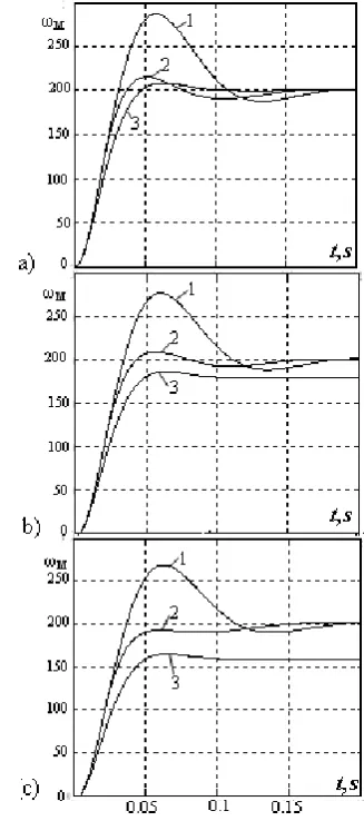
modeling results obtained using variable structure and conventional velocity controllers are presented in Figure 6.
Figure 6. Comparisonof dynamicalresponse curves of the mechatronic system with different kinds of velocity controllers: a – in the idle case, b – in the static load
The curves obtained using velocity controller ad-justed under the symmetrical optimum condition are denoted by number 1, in the case of using variable structure velocity controller VSC (with fuzzy logic based or programmable delay time definition device) – by number 2, and in the case of using velocity control-ler adjusted under the quantitative optimum condition – by number 3. It is seen from Fig. 6 that in all cases the rapidity of the mechatronic servo system with VSC has been increased comparing to the drives with conventional P an PI type velocity controllers. Hence the dynamical quality of the mechatronic servo system has been improved using VSC. Furthermore, the dyna-mical characteristics of the mechatronic system using VSC with fuzzy logic based delay time definition de-vice are practically identical to the dynamical quality of the system using VSC with programmable delay time definition device. Consequently, both P control law delay time definition devices are suitable for the implementation of the proposed dynamical quality improvement technique.
5. Conclusion
The means of dynamical quality improvement of a mechatronic servo system based on velocity control-lers of variable structure application are presented in this article. Two methods of the velocity controller structure change in dependence on the static load level of the system are proposed and investigated. The first method is based on the fuzzy logic methodology and the second one – on the preprogrammed "Lookup Table" application.
It is shown that the Luenberger observer could be applied for the static load current of the system estimation. The input-output dependences of the fuzzy logic based delay time definition device and program-mable delay time definition device ensuring high dynamical quality of the mechatronic servo system independently on the static load conditions are defi-ned. The presented simulation results of the mechatro-nic servo system confirm the suitability of the proposed dynamical quality improvement technique.
References
[1] C. Kessler. Über die Vorausberechnung optimal abgestimmter Regelkreise. Teil III: Die optimale Einstellung des Reglers nach dem Betragsop-timum. Regelungstechnik, Vol.3, No.2, 1955, 40-49.
[2] C. Kessler. Das symmetrische optimum. Teil 1. Regelungstechnik, Vol.6, 1958, No.11, 395-400. [3] C. Kessler. Das symmetrische optimum. Teil 2.
Regelungstechnik, Vol.6, 1958, No.12, 432-436. [4] N. Šulčius, V.A. Geleževičius. Application of
variable structure velocity controller for rapidity improvement of an electric drive. Proceedings of the international conference Automation and control technologies 2004, Kaunas, 114-118. [5] N. Šulčius, V.A. Geleževičius. Investigation of
the Dynamical Quality of the Electromechanical Servo Systems using Variable Structure Cont-rollers. Electronics and Electrical Engineering, No.7(63), 2005, 40-43.
[6] G. Ellis. Observers in control systems: a practical guide. Academic press, 2002.
[7] Information on http://www.mathworks.com.