Copyright © 2015 IJECCE, A ll right reserved
A New Fast 3D Reconstruction Approach using Multiple
View Images
Safaa M. Kareem
Information Systems Department, Faculty of Computer and Information Sciences, M ansoura University, Egypt
Sameh Abd-elghany
Information Systems Department, Faculty of Computer and Information Sciences, M ansoura University, Egypt
Hazem M. El-Bakry
Information Systems Department, Faculty of Computer and Information Sciences, M ansoura University, Egypt
Abstract – The extract key points and matching the pictures are the most paramount reconstruction 3D factors. They almost two-thirds the time of reconstruction. This paper presents a method to extract the most paramount key points, through the use of GrabCut algorithm that elimintes considerable parts of images that does not have its prominence in the reconstructio. Moreover, the proposed algorithm uses siftGPU algorithm that runs parallel to any process more than one image at a time to extract key points and carry out matching process. The experiments show that the proposed system increase the speed of reconstruction and thoroughly good.
Keywords – 3D Reconstruction, S tructure From Motion (S FM), Mash Reconstructionand Multi-View S tereo (MVS ).
I.
I
NTRODUCTİON3D reconstruction is one of the classical and difficu lt problems in co mputer vision, and finds its applications in a variety of different fie lds. In recent years, large scale 3D reconstruction from co mmunity photo collections has become an e me rging research topic, wh ich is attracting more and more researchers fro m acade my and industry. However, 3D reconstruction is e xtre me ly co mputationally e xpensive. For e xa mp le, it may cost more than a day in a single mach ine to reconstruct an object with only one thousand pictures. In the Structure from Motion (SfM) model [1, 2], 3D reconstruction pipeline can be divided into various steps: feature extraction, image matching, track generation and geometric estimation, etc. Among them, image matching occupies the fundamental computational cost, even more than half of all in some case. Moreover, inexact matching results might lead to washout of reconstruction. Therefore, fast and accurate image matching is crit ical for 3D reconstruction.
There are various ways to build reconstruction For e xa mple Reconstruction manually is most Statute method to reconstruct a 3D model for an object real world. but is a method ponderous and very intensive. Level of realism can be achieved [3]. The other way tried to eliminate the voltage on the user . 3D Scanner Variant Gu ide to reconstruction is to let co mputers to take some work, and is a well-established method of 3D scanning. The 3D the scanner is the device that apprehends the detailed informat ion for shape and appearance[4]. Modern developments in techniques scanners and Laser able to apprehend point clouds of scenes the real world, And also Automatically can reveal scene planes and create 3D models without the help of the user which can generate Points dense cloud from total images by photogrammetry tools [5].To create a point clouds typically sharing the
same proble ms fro m noisy and lost data. Makes it very hard to apply the methods of surface reconstruction the direct [6,7], Points cloud doesn't contain the specific edges and borders.
Last method offered by the this paperPhotogrammetry reconstruction regains 3D informat ion fro m a single or more of images. Main ly focused on rebuilding Photos mu lti vie w called stereo vision. Epipolar geo metry describes the features and the linkages between the scene and the 3D geometric projections on two or more images of 2D. Figure 1 shows the idealistic workflow for photogrammetric reconstruction. The first step of photogrammetric reconstruction includes the registration of all input images. This procedure is called structure-fro m-mot ion and includes the computation of intrinsic and e xtrinsic ca mera para meters. For reg istered images, it is possible to compute 3D positions from t wo or mo re corresponding image points. Multi-vie w stereo algorithms use these conditions and compute dense point clouds or triangulated meshes fro m the input scene.
A B Fig.1. Reconstruction Photogrammet ry are recording mu ltip le images (A): is created by the structure fro m motion (B) and 3D geo metry by dense mult i vie w stereo
[8].
The ter ms Multi-vie w Stere o (MVS) simu lates the sense of human sight distance and 3D objects. It uses two or more images fro m various points of view to get the 3D structure of the scene and distance information. Many algorith ms stereo mult ivie w [9, 10] used all the images at the same time to rebuild the 3D model. It requires a high e xpense and also lacks scalability. Furuka wa [ 10] suggested PMVS (mult iple stereoscopic vision correction) and took mu ltiple p ictures of various views of the body to e xtract feature points. It is then expanded abroad to find more of the intervie w points. Furukawa CM VS a lso suggested (Views comp ilation of mult iple stereo) [ 12] in 2010, has been used to ame liorate the image co mb ines numerous susceptibility in order to see the stereo, and sustainable forest management PM VS b roker contacts.
Copyright © 2015 IJECCE, A ll right reserved Steinbruecker et a l. [13] introduced a fast energy-based
approach to stiffly stratify the RGB-D images for a static scene. Khoshelham et al. [14] presented an epipolar search method to gain more precise 3D correspondences and defined adaptive weights for the 3D points based on their theoretical random error to mend registration accuracy of RGB-D data. By comb ining both low level feature correspondences and high level plane primit ives fro m an RGB-D came ra, Dou et al. [14] imp roved indoor 3D reconstruction in challenging cases with incomp lete image features or geometry in formation.
The rema inder of this paper is as follows. Section 2 presents GrabCut algorith m Seg mentation Images . Section 3 presents the method and work Structure fro m motion. Section 4 goes further into the imple mentation details, with Sect ion5 showing the experimental results. Section 6 discusses our conclusions
II.
G
RABC
UTA
LGORİTHMS
EGEMANTATİONI
MAGESThe Grab Cut technique is one of such graph based technique which may be performed using Cut techniques as a part of its refining process of initial user segmentation between foreground and background of image. GrabCut algorith m is primarily developed at Microsoft Research Ca mbridge. There are many segmentation methods Among them graph theoretical techniques have more characteristics in practical applications. These techniques assort the image into mathe matica lly well-de fined structures, ma king the formu lation of image seg mentation problem mo re precise and the computations more efficient. In these techniques the image is treated as a weighted and undirected graph [15] . Graph cut techniques can be used efficiently to resolve image segmentation problems wh ich can be formu lated in terms of energy minimizat ion wh ich in turn can be formulated as ma x-flow problem in a graph [16] . Figure 2 shows the diagram of "GrabCut" approach.
Fg.2. Cut, Graph, image with seeds , segmentation results A simp lified d iagra m o f the " Grab Cut" approach[17]
Results have been better if the the algorithm repeated more than once. Figure 3 shows the results according to
the repeated one . The goal of the imp le mentation of this algorith m, is to eliminate the number of key points, in order to eliminate the time in the extract ion stage of key points.
(a) (b) (c) (d) Fg.3. (a ) Enter image, (b) Repeat algorith m once, (c ) Repeat algorith m three times , (d) Repeat five times the
algorith m.
III.
S
TRUCTUREF
ROMM
OTİON3.1 Over view
Re lative motion between two ca me ras and the object to be reconstructed by Structure from motion is a stereo -based method, to make hypotheses about the 3D object’s shape. Diffe rent contributions and several approaches, e.g Chiuso et a l. 2002 and Hui et a l. 2006 in [18] [19] a re done for this method.
Recent methods for structure from mot ion are described by Christof Hoppe et l. (2013) in [20], who proposed a new method for incre mentally e xtract ing a triangular surface mesh fro m an increasingly growing sparse SfM (structure from motion) point cloud in real-time . And Christof Hoppe et al. (2012) in [ 21] also proposes an online SfM approach that permits the checking of the reconstruction result on site. To guide the user throughout the acquisition, they envisage the existing Ground Sa mpling Distance (GSD) and image redundancy as quality indicators on the surface model.
Fig.4. SfM system Architecture
3.2 Feature detection and the matching
Copyright © 2015 IJECCE, A ll right reserved matrix using the Levenberg-Marquardt method [22] to
optimize the parameters, so the error is minimized. If the re main ing a mount is less than 20 after outlier re moval, thenredo all of the correspondence matching. There a re more than algorith m (to detect features. Matching) in the image, for e xa mp le, (sift. surf)We use (sift). We'll show comparison between Sift Cpu and Sift Gpu. In fact, Used (Sift) because it extracted a big number of key points, and after the first step we need a lot of nu mber of key points, and the variation between the number of points extracted up to about twice what is in the (surf)[23] .
3.3 Methodology Structure from motion
1-First, we choose two locations very far fro m the object and use the overlapping image regions to assess a set of came ra para meters. Therefore, the initia l reconstruction will provide a quite good result. Let RANSA C outlier threshold equals 0.004* ma ximu m image size , and use at least 100 point correspondences of the lowest proportion of the inliers for the homography computation. This group coincide with the camera para meter estimat ion using five-point relative pose algorith m [24]. The bundle adjustment is then carried out using the two initia l images.
2-The ne xt step is to add additional cameras. We picked fro m the 3D locations of the three largest amount of track to subjoin ca mera. In the RANSA C process, we used Hartley et a l. [25] (d irect linear t ransform, DLT) is a method of determining the three dimensionallocation of an object (or points on an object) in space and to initialize the new ca mera e xternal para meters . In addit ion to providing
an upper triangular mat rix K used to estimation the ca me ra internal para meters, we use K to commence the new camera’s focal length. We execute the steps of the bundle adjustment to add the new cameras and supervise the alterations, while keep the rest of the model intact.
3-In the last step, we add a new ca me ra observation point in order to optimize the whole process. If the additional ca mera can observe this point, then join it . If the ma ximu m angle is greater than a threshold (2.0 degrees), then perform the Delaunay triangulation, which can eliminate the points at infinity. Once the new points are added, we carry out the entire bundle adjustment to create an integral model. Keep adding new cameras and reiterate these steps until the point observed in the rema ining images are not adequate for the reconstruction. (We used 20 point as the stop threshold.)
In this work, we use bundler [26], a SfM system to imple ment this part. The bundler can assort the disordered photo collection to a structured set, and thus can be used for afficacious imp le mentation of many computer vision algorith ms. The output is used for PMVS or other redevelopment tools. The system flo w chat of the SfM is shown in Figure 4 .
IV.
3D
M
ODELR
ECONSTRUCTİONAs shown in Figure 5, the system takes diverse images fro m various angles for two various poses of the object in the first stage.
Copyright © 2015 IJECCE, A ll right reserved Then, feature detection and correspondence matching. The
relation of the correspondence features is used for SfM and self-ca librat ion of the camera para meters and scene geometry. When the camera para meters and the corresponding 3D points are gained, they are used for the reconstruction of the 3D mode l.
4.1 Block Reconstruction
When we use (SFM) images to assess the parameters, it is specific image recognition that can deal with them for reconstruction, and we do this procedure before application (CM VS) .We use (CM VS) (Clustering Views for Multi-v iew Stereo ) Furu kawa proposed to ameliorate the capability of the display mult iple stereo vision started. PM VS (Patch-based Multi-view Stereopsis) Provides informat ion which can be counted faster and more precisely .
4.2 3D mesh generation
We have a 3D point cloud. To re-surface o f the body building, and we need to combine 3D points in the grid to form a mo re co mplete 3D model. Thus, we use the PSR (Poisson surface reconstruction) [27] to establish network lin k. Often this algorithm adopted for 3 D surface reconstruction. Can use assess analogy directional 3D surface point, and effectively deal with the noise, and the network user adjustable density.
V.
E
XPERMETALS
ETUP ANDR
ESULTSIn this paper we use the algorithm (GrabCut algorithm Segmentation Images) on multip le set of images about (28) image show in figure (6), and the goal of this algorith m to minimize feature detection to increase the speed matching), as shown in F igure 7.
Fig.6. Input Images
Fig.7. The result after Per-Processing method
Then we use (SFM) to get the point cloud 3D. In steps (PM VS) we get the color point informat ion (3D). The use of (CM VS) in order to ma ke the work (PM VS) faster and more prec isely. As shown in the results it's much faster than the preceding and contain very few holes. As shown in Figure 8 and table 1.
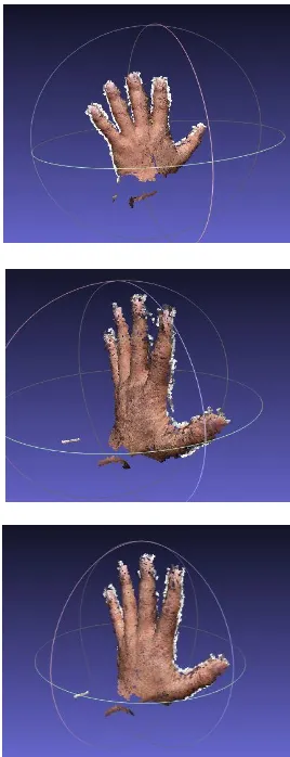
Fig.8. 3D Reconstruction using SFM and PM VS
Table 1: Simulat ion results after preprocessing
Image Size Nu mber of images Feature Detection timing Image Match 3D reconstruction
2000x1500 28 11 sec Nu mber timing 28.000 seconds used
378 47 sec
Copyright © 2015 IJECCE, A ll right reserved Table 2: Simulat ion results before preprocessing
Image Size Nu mber of images Feature Detection timing Image Match 3D reconstruction
2000x1500 28 20 sec Nu mber timing 63.000 seconds used
378 362 sec
In Table 1, we used 28 input images, it consumed time to extract the fundamental points of 11 seconds, and thus become a matching number 378 was fulfilled in 47 seconds. Bringing the time of reconstruction 28 seconds. In Table 2, we have used the same number of images in Table 1 and it was time to ext ract the ma in points of 20 seconds and was the congruent number as in Tab le 1, but was done in 362 seconds. Bringing the time of reconstruction 63 seconds.
The big variation is due at the time of reconstruction between the two tables in the prime treat ment step, which we added in Table 1.
Comparison between CPU and GPU
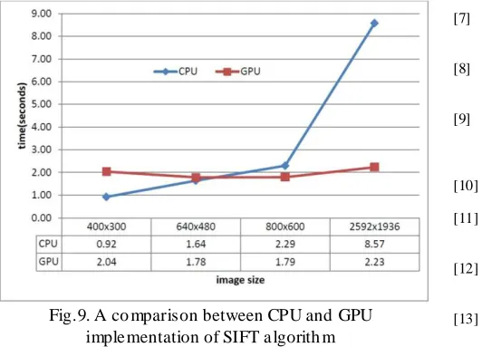
GPU always have a startup overhead time, wh ich can be mentioned by calling at the beginning of the program, this startup time is subtracted in the final GPU run time as it is a one-time cost. The CPU/ GPU run time with various image sizes is shown in Figure (9). For sma ll images, CPU runs faster than GPU. However, as the image size increases, the CPU run time increases basically while the GPU run t ime stays comparatively steady. With image size 2592x1936, the GPU imp le mentation runs almost 4x faster than CPU imp le mentation.[28]
Fig.9. A co mparison between CPU and GPU imple mentation of SIFT a lgorith m
Sift GPU is an application of SIFT [29] for GPU. Sift GPU processes pixels paralle ly to build Gaussian pyramids and reveal Do G Keypoints. Based on GPU list generation[30], Sift GPU then uses a GPU/CPU mixed method to exepditously build compact keypoint lists. Finally keypoints are addressed parallely to get their orientations and descriptors.
VI.
C
ONCLUSIONA new fast 3D reconstruction approach has been presented. This has been done by taking out the paramount points and the image matching system. Expe riments show that we have attained an increase in
speed in the extraction of the primary points and image matching. Through the system that we have suggested. The GrabCut algorith m has played a fundamental role in the achieved speed rate. The proposed approached has increased the speed of matching process ten times or faster while ma intaining accuracy.
R
EFERENCES[1] S. Agarwal, N. Snavely, I. Simon, S. M. Seitz, and R. Szeliski.
Building rome in a day. In International Conference on Computer Vision (ICCV), 2009
[2] D. Crandall, A. Owens, N. Snavely, and D. P. Huttenlocher.
Discretecontinuous optimization for large-scale structure from motion. In Proc. IEEE Conf. on Computer Vision and Pattern Recognition, 2011.
[3] Marc Pollefeys and Luc Van Gool. From Images to 3D Models.
Communications of the ACM, 2002.
[4] Wikipedia. 3D scanner, 2010. http://en.wikipedia.org/wiki/
3D_scanner.
[5] Yasutaka Furukawa and Jean Ponce. Accurate, dense, and robust
multi view stereopsis. IEEE T ransactions on Pattern Analysis and Machine Intelligence, 2010.
[6] Pierre Alliez, David Cohen-Steiner, Yiying Tong, and Mathieu
Desbrun. Voronoi-based variational reconstruction of unoriented point sets. In Eurographics Symposium on Geometry Processing, , 2007.
[7] Michael Kazhdan, Matthew Bolitho, and Hugues Hoppe. Poisson
surface reconstruction. In Eurographics Symposium on Geometry Processing, 2006.
[8] Sameer Agarwal, Yasutaka Furukawa, Noah Snavely, Brian
Curless, Steven M Seitz, and Richard Szeliski. Reconstructing Rome. IEEE Computer, 2010.
[9] M. Brown and D. G. Lowe, “Unsupervised 3D object
recognition and reconstruction in unordered datasets,” in In Proceedings of the international conference on 3D digital imaging and model ling, pp. 56–63, 2005.
[10] Y. Furukawa and J. Ponce, “ dense, and robustmultiview
stereopsis ,” in Pattern Analysis and Machine Intelligence, 2009.
[11] Y. Furukawa and J. Ponce,“Accurate, dense, and robust
multi-view stereopsis,” in Computer Vision and Pattern Recognition, pp. 1–8, 2007.
[12] Y. Furukawa, B. Curless, S. M. Seitz, and R. Szeliski, “Towards
Internet -scale Multi-view Stereo,” in Computer Vision and Pattern Recognition, 2010.
[13] F. Steinbrucker, J. Sturm, and D. Cremers, “Real-time visual
odometry from dense RGB-D images,” in Proc. IEEE Int. Conf. Comput. Vis.Workshops, Nov. 2011, pp. 719–722.
[14] M. Dou, L. Guan, J.-M. Frahm, and H. Fuchs, “Exploring
high-level plane primitives for indoor 3D reconstruction with a hand-held RGBD camera,” in Proc. Asian Conf. Comput. Vis., vol. 2. Nov. 2012,pp. 94–108.
[15] Basavaprasad B., and Ravindra S. Hegadi.; “Graph theoretical
approaches for image segmentation”, Aviskar – Solapur University Research Journal, Volume: 2, Pages: 7-13, 2012.
[16] Ravindra S. Hegadi, Basavaraj A Goudannavar, "Interactive
Segmentation of Medical Images Using GrabCut", IJMI, Volume: 3, Issue: 3, Pages: 168-171, 2011.
[17] http://www.cs.ru.ac.za/research/g02m1682
[18] Chiuso, A., Favaro, P., et al., Structure from motion causally
integrated over time, IEEE T ransactions on Pattern Analysis and Machine Intelligence, vol. 24, no. 4, pp. 523-535, 2002.
[19] Hui, J., A holistic approach to structure from motion, Computer
Science Dissertation, University of Maryland, USA, 2006
[20] HOPPE, KLOPSCHITZ, DONOSER, BISCHOF Incremental
Copyright © 2015 IJECCE, A ll right reserved
Clouds Institute for Computer Graphics and Vision, Graz University of T echnology, Graz, Austria 2013
[21] HOPPE ET AL.: Onlıne Feedback For Sfm Image Acquısıtıon
Institute for Computer Vision and Graphics Graz University of Technology Graz, Austria 2012
[22] P M Panchal1, S R Panchal2, S K Shah3, A Comparison of SIFT
and SURF,2013.
[23] Volodymyr Kindratenko, Guochun Shi Evaluation and
Exploration of Next Generation Systems for Applicability and Performance) 2011
[24] D. Nistér, “An efficient solution to the five-point relative pose
problem,” IEEE Transactions on Pattern Analysis and Machine Intelligence 2, vol. 26, pp. 756– 777, 2004.
[25] Y. Furukawa and J. Ponce, “dense, and robustmultiview
stereopsis ,” in Pattern Analysis and Machine Intelligence, 2009.
[26] N. Snavely, “Bundler: Structure from motion (sfm) for
unordered image collections.”
[27] M. Kazhdan, M. Bolitho, and H. Hoppe, “ Poisson surface
reconstruction ,” in Proceedings of the fourth Eurographics symposium on Geometry processing, 2006.
[28] D. G. Lowe. Distinctive image features from scale-invariant keypoints . International Journal of Computer Vision, November 2004.
[29] G. Ziegler, et al. GPU point list generation through histogram pyramids. In Technical Report, June 2006.
[30] S. Lazebnik, Y. Furukawa, and J. Ponce, “Visual hull data sets.”