Development of an Sms Controlled Car Security
System Via Voice Recording and Image Capturing
Techniques
Adewumi Adebayo Segun
1*and Adeleke David Kehinde
21Department of Pure and Applied Physics, Ladoke Akintola University of Technology, P.M.B. 4000 Ogbomoso, Oyo State, Nigeria. 2Department of Physics, Adeleke University, P.M.B 250, Ede, Nigeria.
Date of publication (dd/mm/yyyy): 16/04/2018
Abstract – This paper present an SMS controlled car security system with image capturing and voice recording technique. The device was interfaced with PIC, GPS and GSM modem which is controlled by mobile phone. The whole setup consists of two parts, the transmitting part and the receiving part. The transmitting part is composed of the microcontroller which is the brain box of the whole system, the global positioning system (GPS) which is use to obtain the precise location and time, GSM modem (Siemens TC35) which sends and receives messages and voice call, extremely small snapshot camera which takes the pictures of the car thieves, process it into Jpeg file and forward it to the PIC through a serial port, and voice recording device which receives the conversation of the car thief and foward it to the receiving part for storage.The receiving ends consists of the nRF2401 receiver and the memory card which serves as the storage device for storing data files. This device is able to execute command issue via text and messages from the mobile phone. The microcontroller queries the modem for messages from the users. The user can make a voice call and listen to the conversation made by the car thieves through the hidden condense microphone.This developed car security system is a perfect choice for tracking stolen vehicle and its intruders.
Keywords – PIC Microcontroller, GSM Modem, Mobile Phone, Transceiver, condense microphone, snapshot Camera.
I. I
NTRODUCTIONFollowing the advent of the first modern automobile in the year 1886 by German inventor Karl Benz, car theft accompanied car production. Hence the need for a car security system and the first one was invented by an unknown prisoner from Denver in the year 1913 where the alarm sounds when the engine is cranked, a revised version was made in the year 1916 which would buzz if the car ignition system is tampered with [11]. Ever since, several car securites have been developed and published by researchers [1], [2], [3] and [5]. In Nigeria statistics conducted over the years showed a very high increase in car theft. Many international and local organizations have expended good resources to combat this debilitating rate of car theft but with little or transient reduction. The thieves are devising a smarter stealing method that requires more powerful security system to counter. To overcome these problems; this paper proposes a car security system based on image capturing, voice recording and short message service (sms) activation and deactivation techniques to secure cars. This tracking security system is composed of Global Positioning system (GPS), GSM modem, camera
and voice-recording device. Microcontroller is the main brain box which control the whole system. It is also known as microprocessor with the use of GPS system, tracking at different distance or range can be done from the receiving system. The short message service (sms) is used as medium to transmit the voice recorded by the sensor to the user. The capture process is based on the camera mounted in the hidden part front part of the car which captures the image and installs it in the GSM modem before it is being sent to the user. The whole process is controlled by the installed microcontroller. This car security system with excellent image capturing, voice recording and sms deactivation and activation techniques is a great development to the car security systems since any stolen car can be tracked, traced and the images with the conversations of the people involved can be retrieved.
II. M
ATERIALS ANDM
ETHODSThe design process were divided into two parts: Hardware and Software parts
A. Hardware Design
Microcontroller ____ PIC microcontrollers
(Programmable Interface Controllers) are electronic circuits that can be programmed to carry out a vast range of tasks [4]. PIC18F452: There are two memory blocks in each of the PIC18F452 devices. The program memory and data memory have separate buses so that concurrent access can occur. The PIC devices have a 13-bit program counter capable of addressing an 8k words * 14 bits of flash program memory, while PIC devices have 4K works * 14 bits. The data memory is partitioned into multiple banks which contain the general purpose registers and the special function registers. Each bank extends up to 7Fh (128 bytes). The lower locations of each bank are reserved for the special function registers.
GPS Module (SIRF III) ___ The system can correctly
send the position of vehicle to the server center by GPS positioning. The GPS module obtains the precise locality by parsing received GPS signal [4] and [6]. The role of this module is to locate the current position of the car and thus send the GPS coordinates through GSM
JPEG Camera (C328) ___ C328 VGA camera module
the JPEG engine and transferred to the host through serial port.
GSM Modem (Siemens TC35) ____ The GSM modem is
a wireless modem that works with a GSM wireless network [10]. The wireless modem behaves like a dial up modem. The main difference between them is that a dial –up modem sends and receives data through a fixed telephone line while a wireless modem sends and receives data through radio-waves [8]. The GSM modem can send the information out by SMS (short message service) message, including real time position of the “lost” car and even the images “the driver”.
High Speed Transceiver (nrf2LO1+) --- The nrf24LO1 is single chip 2.4GHz transceiver with an embedded baseband protocol, designed for ultra low power wireless applications [9]. The nRFL01 is designed for operation in the worldwide 2.4GHz ISM frequency band. The air data rate is configured to 2Mbps
Fig. 2a: Functional Block diagram of the Receiving section of the car security system
Fig. 2b. Functional Block diagram of the Transmitting section of the car security system
B. Software Design
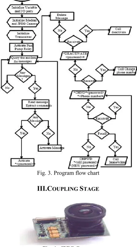
The system software was written in basic language. It uses AT command for its operation. The flowchart for the operation is shown in figure 3
Fig. 3. Program flow chart
III.C
OUPLINGS
TAGEFig. 4. JPEG Camera
Fig. 5. NRF2L01 Transceiver Antenna
Fig. 7. Front view of the car security system
IV
.
W
ORKINGP
RINCIPLEWhen the various connection ports available on the car tracking device were connected to the car for proper transmission of signal. The car battery helps to set a starting value for the various connection on the port. The modem, JPEG camera and transceiver will be immediately initialized to prepare them for the tracking process.When command is sent through SMS to the car security system, the modem receives the SMS sent and stores it in the Synchronized Identification Module card (SIM Card). The microcontroller queries the Modem for messages from the user. It then reads out any message found through the serial port to the microcontroller. The microcontroller then passes the received for the password command and the symbols; "*" and "#" which denotes the start and end of the message (figure 8). The stored password is compared with the received password and the command, if valid, is executed. When the device is activated, the red LED will be ON and when an intrusion is detected, the yellow LED blinks (Figure 11). When the user makes a voice call, the modem detects the voice call and signifies the microcontroller by sending "RING". The PIC on receiving this through its serial board sends or replies the AT command, ATA to pick or answer the voice call made by the user. The user can then listen to the conversations being made by the car occupants. This is made possible by a hidden condense microphone conneected to the modem microphone inputs. If the conservationis useful or worth storing, the user might start recording the conservation by using the sound recorder on his/her Phone which can take place any where (figure 12). The Jpeg camera connected to the car security unit is enabled by the PIC to start taking pictures wherever there is an intrusion. The camera takes the pictures, process it into a JPEG file and then send it to the PIC through its serial port (Figure 13). The PIC relays the files stream through the nRF2401 transceiver (primarily configured as a transmitter) to the other module which receives this file stream and passes to the PIC controller present in the interval module which saves these file stream in a memory card as a Jpeg file.
Fig.8:Command sent to query the system for security breach
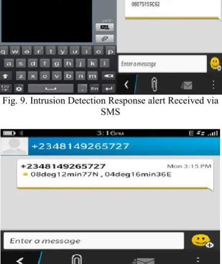
Fig. 9. Intrusion Detection Response alert Received via SMS
Fig. 10. Car Intruder Location received via SMS
Fig. 12. Recording of conversations in the vehicle through voice call
Fig.13. File stream of image saved in a memory card
Fig. 14. sample of the image captured by the camera.
V. C
ONCLUSIONIn this paper, it has been demostrated that an SMS controlled car security system via voice recording and image capturing techniques is realizable. The effectiveness of the developed car security system is seen in its abilities to snapshot, record voices, alert through SMS, immobilized and relate location information about a stolen vehicle. Hence, this developed car security systems is a perfect choice for tracking stolen vehicles and equally arrest the intruders since it has provided a good platform for security agents to work on when the need arises.
Programming Code of the Car_Security include nrf24l01_tx
include SERIAL_CAMERA SYMBOL door1 = portB.0 SYMBOL door2 = portB.1 SYMBOL door3 = portB.2 SYMBOL door4 = portB.3 SYMBOL boot = portB.4 SYMBOL BUNNET = portB.5 SYMBOL RLA = PORTC.0 DIM TXT2 AS STRING[25] dim DLY AS WORD DIM TMP AS BYTE DIM MSGNO AS BYTE DIM PNO AS STRING[30] DIM MSG AS STRING[30] DIM TIM_ AS LONGINT DIM TIM AS BYTE
DIM CMD AS STRING[10] DIM CMD1 AS STRING[10] DIM PASS AS STRING[6] DIM BUFFER AS BYTE[32] DIM TRIP AS BYTE SIZE AS BYTE ERRR AS BYTE TRIPSTO AS BYTE TRIPSTO1 AS BYTE
SUB PROCEDURE INTERRUPT() INTCON.GIE = 0
PIR1.TMR1IF = 0 'CLEAR FLAG. INC(TIM_)
MESSAGE TIMING IF (TIM_ > 11) THEN TIM_ = 0
INC(TIM)
IF (TIM > 9) THEN TIM = 9
END IF END IF
INTCON.GIE = 1 END SUB
SUBPROCEDURE SEND_MESSAGE(DIM BYREF TXT AS STRING[30],DIM BYREF PHONE AS STRING[15])
DIM DEB AS STRING[20] DEB = "AT+CMGS="
UART1_Write_Text(DEB) SEND AT COMMAND
UART1_Write_Text(PHONE) ' PHONE NUMBER TO SENT TO
UART1_Write(13)
DELAY_MS(2000) 'WAIT UART1_Write_Text(TXT)
UART1_Write(26) 'send SEND CTRL+Z UART1_Write(13)
END SUB
SUB PROCEDURE CHECK()
IF (IR = 0) AND (TRIPSTO = 1) THEN 'NEW BREACH TXT2 = "IR LINK CROSSED "
SEND_MESSAGE(TXT2,PNO)
TRIPSTO = 1 'RESET CURRENT DETECTION STATE END IF
IF (TOUCH = 1) AND (TRIPSTO1 = 0) THEN 'DETCT NEW TOUCH
TXT2 = "IR DETECTION " SEND_MESSAGE(TXT2,PNO)
TRIPSTO1 = 0 'RESET CURRENT DETECTION STATE
END IF
IF (IR = 1) THEN TRIPSTO = 1 END IF
IF (TOUCH = 0) THEN TRIPSTO1 = 0
END IF END SUB
WHILE (UART1_Data_Ready() = 0)
UART1_Write_Text("AT") UART1_Write(13) UART1_Write(10)
DELAY_MS(500) WEND
UART1_Write_Text("AT+CMGF=1") UART1_Write(13) UART1_Write(10) 'TEXT MODE END SUB
main:
TRISB = %01111111 TRISE = 255
TRISC.0 = 0
'CONFIGURE SERIAL PORT. UART1_Init(9600) '9600bps TRISC.6 = 0
TRISC.7 = 1 TIM_ = 0 TIM = 0
PIR1.TMR1IF = 0 'CLEAR FLAG.
PIE1.TMR1IE = 1 'ENABLE TIMER1 INTERRUPT. INTCON.RBIF = 0 'PORTB ON CHANGE INTERRUPT FLAG CLEARED
INTCON.PEIE = 1 'ENBLE ALL UNMASKED INTERRUPT.
INTCON.GIE = 1 'ACTIVATE GLOBAL INTERRUPT.
T1CON = %00110101
INI_MODEM() 'INITIALISE THE MODEM DELAY_MS(2000)
'WAIT FOR MODEM TO BE INLINE. TRIP = 0
CMD = "AT+CMGR=1" CMD1 = "AT+CMGD=0"
INIT_SERIAL_CAMERA(PORTD,0,1) 'INITIALISE THE SERIAL CAMERA TO USE SOFTWARE SERIAL ON PIN RDO AND RD1
INIT1_24L01(PORTC,1,2,3,4,5) 'CE,CSN,SCLK,MOSI,MISO
INIT2_24L01(0,20,2) 0dB , CHANNEL 20 , 2MbPS STARTT:
SIZE = 0 TMP = 0 TIM = 0 ERRR = 0 MSG = ""
UART1_Write_Text(CMD) UART1_Write(13) //send read command
WHILE (TMP <> "*") 'LOOK FOR THE START OF THE MESSAGE.
if (UART1_Data_Ready() = 1) then TMP = UART1_Read()
INC(ERRR) 'COUNT RECEIVED CHARACTERS.
end if
if (TIM > 2) then
if (ERRR < 30) then 'SEE IF NO MESSAGE. GOTO NO_MSG
end if
GOTO MSG_END end if
WEND MSG[0] = "" SIZE = 1
'START FOUND... READ MESSAGE TIM = 0
WHILE (TMP <> "#") 'LOOK FOR THE END OF THE MESSAGE.
if (UART1_Data_Ready() = 1) then TMP = UART1_Read()
MSG[SIZE] = TMP INC(SIZE)
end if
if (TIM > 2) AND (MSG[4] = "#") then GOTO MSG_END1
end if
if (TIM > 2) then GOTO MSG_END end if
if (SIZE > 6) THEN 'MORE THAN MAX LENGHT OF OUR COMMAND
GOTO MSG_END1 end if
WEND
'READ THE PASSWORD FROM THE MESSAGE. FOR TMP = 0 TO 5
IF (PASS[TMP] <> MSG[TMP + 6]) THEN GOTO MSG_END 'PASSWORD IS WRONG... END IF
NEXT TMP
'PASSWORD CORRECT , PROCEED ERROR FINDING IN THE MESSAGE... if (MSG[4] <> "#")then
GOTO MSG_END end if
if (SIZE < 5) then GOTO MSG_END end if
MESSAGE CONTAINS NO ERROR PROCEED ' SEARCH FOR COMMAND...
IF (MSG[0] = "D") AND (MSG[1] = "A") AND (MSG[2] = "C") AND (MSG[3] = "T") THEN GOTO DACT_
END IF END IF
IF (MSG[0] = "I") AND (MSG[1] = "M") AND (MSG[2] = "O") AND (MSG[3] = "B") THEN GOTO IMOB_
END IF
IF (MSG[0] = "C") AND (MSG[1] = "H") AND (MSG[2] = "P") AND (MSG[3] = "W") THEN GOTO CHPW_
END IF
INC(MSGNO)
IF (MSGNO > 56) THEN
MSGNO = 49 'RESET TO LOCATION 1 END IF
CMD[8] = (MSGNO) DELAY_MS(2000)
IF (INTCON.RBIF) THEN ' IF ANY DOOR , BUNNET OR BOOT HAS BBEN OPENED INTCON.RBIF = 1 'CLEAR THE PORTB ON CHANGE INTERRUPT
TRIP = 1 'SET TRIP FLAG
END IF
IF ((TRIP = 1) AND (TIM = 9)) 'IF SECURITY HAS BEEN BREACHED AND TIMER ELAPSED IF (CAM_PIX(320_240,BUFFER) = 1) THEN 'SNAP A PICTURE OF 320X240 PIXELS
NRF24L01_SEND(BUFFER) 'SEND DATA TO THE OTHER UNIT
WHILE (CAM_READ())
NRF24L01_SEND(BUFFER) 'SEND TILL END OF PICTURE DATA
WEND END IF
TIM = 0 'CLEAR THE TIMER END IF
GOTO STARTT DEL_MSG:
' DELETE THE MESSAGE.
UART1_Write_Text(CMD1) 'SEND AT+CMGD = MSGNO
UART1_Write(13) GOTO SK1 MSG_END: GOTO DEL_MSG NO_MSG:
GOTO SK1
***COMMANDS*** DACT_:
STATUS = FALSE TRIP = 0
GOTO DEL_MSG ACTV_:
STATUS = TRUE GOTO DEL_MSG IMOB_:
RLA = FALSE GOTO DEL_MSG CHPW_:
'READ THE NEW PASSWORD FROM THE MESSAGE.
FOR TMP = 0 TO 5
PASS[TMP] = MSG[TMP + 6] NEXT TMP
EEPROM_WRITE(0,PASS) 'WRITE THE NEW PASSWORD TO EEPROM
GOTO DEL_MSG NKNOWN_CMD: GOTO DEL_MSG end.
R
EFERENCES[1] Amusa K.. A Nuga O.O, Adetomi A.A, (2012), “Design of SMS- enabled car security system” Transnational Journal of science and Technology edition vol. 2, No 10.
[2] Ibrahim V. M, Asogwa A.V, Musa S.Y (2012), “GSM Based Anti theft security system using AT&T command” International Journal of computational Engineering Research Vol.2 Issue 5. [3] Jiwa Abdullah (2011),“The design of mobile control car security
system” IACSIT International Journal of Engineering and Technology,Vol 3,No 3.
[4] Koji Hasegawa (2001) "GPS Receiver and GPS Reception Method", US patent Application publication.
[5] Kunja p. Tann et al (2010) Instant Theft Alert and Tracking System in car, International Journal of Computer Applications (0975-8887) volume 1. No. 21.
[6] Microchip Technology Inc: PIC18FXX2 Data sheet 2002, quality management system certified by DNA ISO/Ts 16949.
[7] Muka Bhardwaj (2007) "Academic's Dictionary of Electronics", Academic India publishers New Delhi-110008.
[8] Ruchita J.S, Anuradha P.G (2012), “GSM based car security system” International Journal of Engineering and innovative Technology (IJEIT) volume 2, Issue 4.
[9] ShenjJay Automation Technologies co, SiRF star III GPS Module
SJ-301 2007 specification retrieved from
http://www.sja.com.twon 6 June 2013.
[10] Siemens AG PCM, Wireless Modules: Siemens TC 35 Terminal,
order no: A31008-H8600-A1-1-7619. retrieved
fromhttp://www.siemens.com/ on 10 June 2013.
[11] Prisoner Devices stolen Automobile Alarm "popular mechanics Heart Magazines:509 April 1913 ISSN 0032-4558 retrieved from https://en.wikipedia.org/wikiCar_alarm on 04 May 2013.
A
UTHORS’
P
ROFILESAdewumi Adebayo Segunreceived the M.Tech and Ph.D. degrees in Electronics and Communication Physics from Ladoke Akintola University of Technology, (AUTECH), Ogbomoso, Nigeria in 2011 and 2016, respectively. Dr. Adewumi has been with the department of Pure and Applied Physics (LAUTECH) as an academic staff and Ele- -ctronics and Radio Communication researcher since 2008. His research interests and publications are in the area of the design and implementation of new configuration of Antennas, characterising and modeling of Radiowave propagation loss and development of electronics instrumentation systems. He is presently the coordinator of LAUTECH Radio and Space Communication Research Group.