Structural design and parameter determination for fluted-roller fertilizer
applicator
Shan Zeng
1,2,
Yipeng Tan
1,2,
Yu Wang
2,
Xiwen Luo
1,2*,
Lamei Yao
1,2,
Dengpan Huang
1,2,
Zewen Mo
2(1. Key Laboratory of Key Technology on Agricultural Machine and Equipment, Ministry of Education, South China Agricultural University, Guangzhou 510642, China;
2. College of Engineering, South China Agricultural University, Guangzhou 510642, China)
Abstract: The instability of the motion layer of fertilizer particle influences the precision and the accuracy of the amount of fertilizer application in the working process of fluted-roller fertilizer applicator. The characteristics of the motion layer were investigated, and a systematic scheme was proposed for designing the structures of fertilizer-filling cavity, fertilizer-filling surface and fertilizer-delivery cavity. The key parameters of the structure were studied by discrete element method. It was figured out that to ensure the smooth operation of fertilizer applicator, the fertilizer-filling angle was 105°, fertilizer-contact angle should be large than 100°, and the fertilizer-resistance angle should be smaller than 35°. Moreover, the stability of fertilizer motion morphology was investigated to verify the design. The results showed that when the roll rotational speed was larger than 120 deg/s, compared with the conventional design the CV of the amount of fertilizer application was reduced from 1.5%-3.5% to 0.5%-1.0%, and the accuracy of the fertilizer discharge was improved with the square of the correlation coefficient between the amount of fertilizer application and the roll rotational speed was larger than 0.999. It was deduced from the results that the precision and accuracy of the amount of fertilizer application are improved via eliminating the driving layer and enhancing the stable filling and conveying of the forced layer.
Keywords: fertilizer applicator, fluted-roller, precision fertilization, structural design, structural parameters
DOI: 10.25165/j.ijabe.20201302.4999
Citation: Zeng S, Tan Y P, Wang Y, Luo X W, Yao L M, Huang D P, et al. Structural design and parameter determination for fluted-roller fertilizer applicator. Int J Agric & Biol Eng, 2020; 13(2): 101–110.
1 Introduction
Variable Rate Fertilization (VRF) technology is an important part of the development strategy of precision agriculture[1]. To date, on-demand fertilization is achieved, with modern techniques such as 3S (GPS, GIS, RS) technology and the technology for information rapid acquisition of nutrient in farmland and crop nutrient, and Expert System[2]. It has been proved by the related studies that VRF brings obvious economic benefits from fertilizer reduced application[3], and the precision and accuracy of amount of fertilizer applicator are not conducive to the effective absorption of fertilizer and the yield of crops[4,5].
There are three types of VRF, including disc fertilizer spreader, spiral (screw) fertilizer applicator and fluted-rolled fertilizer applicator. Disc fertilizer spreader is mainly used for top
Received date: 2019-02-26 Accepted date: 2020-02-22
Biographies: Shan Zeng, PhD, Associate Professor, research interests: agricultural mechanization and automation, Email: [email protected]; Yipeng Tan, Graduate student, research interests: agricultural mechanization and automation, Email: [email protected]; Yu Wang, PhD, Associate Professor, research interests: agricultural mechanization and automation, Email: [email protected]; Lamei Yao, Graduate student, research interests: agricultural mechanization and automation, Email: [email protected];
Dengpan Huang, Graduate student, research interests: agricultural mechanization and automation, Email: [email protected]; Zewen Mo,
Undergraduate student, research interests: agricultural mechanization and automation, Email: [email protected].
*Corresponding author: Xiwen Luo, Professor, research interests: agricultural mechanization and automation. South China Agricultural University, Key Laboratory of Key Technology on Agricultural Machine and Equipment, Ministry of Education, Guangzhou 510642, China. Email: [email protected].
application. It adjusts the application width by controlling the rotational speed of the disc, but the uniformity of the amount of fertilizer application is deficient[6]. Some good research results were achieved by optimizing the structure of the disc to optimize the uniformity of fertilizer application[7]. For spiral (screw) fertilizer, its fertilizer screw can be divided into vertical type[8] and horizontal type[9], which adjusts the rotational speed of the fertilizer screw to controls the amount of fertilizer application. With the virtue of simplicity of structure, stability and maneuverability of operation the fluted-rolled fertilizer applicator has been widely applied in the field of VRF.
Fluted-roller fertilizer applicator, which adjusts the amount of fertilizer application by controlling two variables, the roll rotation speed ω and the working length of the roll L (feed-roll length), has the characteristics of stable response of actuator and flexible control strategy. The feed-roll length L is controlled by axially moving the roller[10] or open-down the movable baffle for the roller[11] for different type of machines. Since the accuracy of the amount of real-time fertilizer highly depends on the response speed and accuracy of system, the embedded or PLC-based two-variate control system[11-13] has made great progress. The precision of the roller rotation speed and the response time can be improved significantly under the PID control algorithm[14]. More researchers have developed some two-variable control strategies based on optimized algorithm models to further improve the control accuracy[15-17]. However, there are currently few studies on the structural design of the fertilizer applicator.
type[21]. The common point of three types is that there is a gap between the fertilizer-resistant part and the roller during the operation. The amount of fertilizer in this structure can be regarded as two parts, that is, the amount in forced layer and the amount in driving layer. The forced layer is the particles in the groove of the roller, and its movement is forced by the rotation of the roller. The movement is relatively stable. However, since the groove space cannot be fully filled, the forced layer filling coefficient Ψ is introduced to indicate the forced layer filling rate. The driving layer is on the outer side of the outer circumference of roller. Due to friction between the fertilizer particles and the roller or other fertilizer particles, it moves with the roller. However, the formation of driving layer is affected by various factors such as the mechanism material, the roller rotational speed and the characteristics of the fertilizer material. Existing research usually introduce a characteristic coefficient λ of the driving layer to estimate its effect. The one-cycle amount of fertilizer q and the total amount of fertilizer Q as:
(S )
q dL
l
(1)
Q=qωt (2) where, S is the cross-sectional area of single-groove, cm2; d is the outer diameter of roller, cm; γ is the bulk-density of fertilizer, g/cm3; l is the groove intercept (the outer circumference is divided by the number of groove, cm ; ω is the roller rotational speed, r/s.
a. Fixed type b. Flexible discharging flap type c. Soft brush type Figure 1 Schematic diagram of the traditional internal structures
In a simplified research model, the amount of fertilizer is usually considered as a linear function of the roller rotational speed ω or the feed-roll length L. However, in recent years, studies have shown that the amount of fertilizer and the feed-roll length are not strictly linear, due to changes in the characteristic coefficient λ of the driving layer[22]. The characteristic coefficient λ and the filling coefficient Ψ also vary on the rotational speed ω[23]. Researchers have studied the characteristics of the driving layer through DEM (Discrete Element Method)[24], but further studies it still be needed to provide effective solutions.
The preliminary experiments conducted by the authors showed that the moving speed of fertilizer particles is increasing with the increase of roller rotational speed, but it is not linear, and the instantaneous velocity of a single fertilizer particle is always in a random state of change and varies greatly at different times. Because of the driving layer, the interface between the forced layer and the driving layer becomes indistinct, so that it is difficult to estimate the total amount of fertilizer in the forced layer. The driving layer on the outside of roller ensures the filling of forced layer inside the groove. The smooth discharge of particles in driving layer ensures the smooth operation of the roller. The vibration of operating machine further impacts the stability of fertilizer-resistant parts, and the fertilizer particles in the gap are more likely to slip.
In this study, a novel structure of fluted-roller fertilizer
applicator is proposed to enhance the precision of the amount of fertilizer, which ensures the linear relationship between the amount of fertilizer and the rotational speed of roller. The design involves the key parameters of the fertilizer-filling cavity, the fertilizer-filling surface and the fertilizer-delivery cavity. It removes the discharge of the driving layer, and be able to eliminate the influence of the characteristic coefficient λ on the accuracy of the amount of fertilizer, and greatly reduces the difference of the filling of forced layer at different roller rotational speeds. A well-designed fertilizer-contact angle can ensure the formation of the internal driving layer, and the filling of forced layer at different roller rotational speed, especially under high-speed operation. The fertilizer-filling surface and the fertilizer-filling angle should be properly designed to guarantee that all the particles in the internal driving layer are blocked smoothly. The fertilizer-conveying cavity with fixed boundaries would guarantee the amount of fertilizer is controllable in the forced layer.
2 Structure and operation
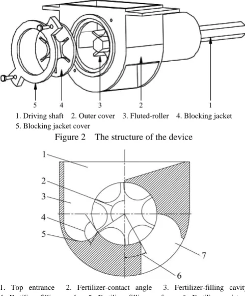
As the shown in Figure 2, the fertilizer applicator includes outer cover, fluted-roller, blocking jacket, blocking jacket cover and drive shaft. Considering the study mainly focuses on the structural parts related to the fertilizer delivery, the prototype does not show the unrelated components such as the fertilizer discharge mouth and pipes. In this fertilizer applicator, the feed-roll length is controlled by axial moving of roller, but it is still suitable for the type of movable baffle. The internal structure of the device (Figure 3) includes the top entrance, the fertilizer-filling cavity, the fertilizer-filling surface, the fertilizer-delivery cavity and the fertilizer outlet. The shape of the fertilizer-filling cavity and the fertilizer-filling surface is determined by the fertilizer-filling angle and the fertilizer-contact angle. The area of the fertilizer-filling angle to the edge of the fertilizer-resistant angle is the fertilizer-conveying cavity. The fertilizer-filling angle α is the angle between the faces of fertilizer-filling surface and the outer surface of the roller, and the other end of the fertilizer-filling surface is tangent to the vertical surface (the distance between the vertical surface and the roller is referred to the conventional structure). The fertilizer-contact angle β is the arc of the outer-circle of the roller in the area of the fertilizer-filling cavity. The fertilizer-delivery cavity is determined by the fertilizer-contact angle β and the fertilizer-resistant angle δ.
1. Driving shaft 2. Outer cover 3. Fluted-roller 4. Blocking jacket 5. Blocking jacket cover
Figure 2 The structure of the device
1. Top entrance 2. Fertilizer-contact angle 3. Fertilizer-filling cavity 4. Fertilizer-filling angle 5. Fertilizer-filling surface 6. Fertilizer-resistant angel 7. Fertilizer outlet
Figure 3 Schematic diagram of the internal structure
1. The in-groove stage 2. The internal delivery stage 3. The filling stage 4. The stable delivery stage
Figure 4 Four stages of the discharge process
The fertilizer-contact angle β determines the zone of driving layer inside the machine, and has significant effect on the filling performance of the device in the forced layer. If β is too small, the forced layer cannot be filled fully when the roller rotational speed is high. While a too large β will affect the rage of the fertilizer-delivery cavity, and impact the stability of delivering.
The fertilizer-filling angle α determines the guide-back ability of the fertilizer-filling surface in the inner driving layer. Without a properly designed fertilizer-filling angle, the fertilizer particles are easy to be squeezed or sheared in the filling stage when the rollers enter the fertilizer-conveying cavity, so that the torque of the roller increases sharply, and the smoothness of operation declines.
In addition, the span of the fertilizer-conveying cavity should be greater than the span of one groove of roller (for example: a six-groove fluted-roller should be more than 60°). A reasonable fertilizer-resistant angle δ can ensure that the discharge process is synchronized with the rotation of the roller, and avoids the advance slippage of the fertilizer caused by the vibration of the machine during the field operation. Once, the fertilizer-resistant angle δ is too large, the fertilizer cannot be completely discharged, and some fertilizer will be brought into the device with the groove.
3 Performance indicators
The study aims to investigate the amount of fertilizer application in fluted-roller fertilizer applicator under different roller rotational speeds. The key performance indicators are based on the amount of fertilizer application[26]. The one-cycle amount of fertilization q and the total mass of fertilization Q are as following: qL S z (3) Q=qωt (4) where, S is the cross-sectional area of single-groove, cm2; γ is the bulk-density of fertilizer, g/cm3; L is the feed-roll length, cm; ω is the roller rotational speed, r/s; t is the time of fertilization.
The accuracy of the amount of fertilizer Q is determined by its linear relationship with the roller rotational speed ω. Therefore, the accuracy of the amount of fertilizer application is evaluated by observing the regression equation between Q and ω and the square of the correlation coefficient r2[27,28].
According to Equation (4), when L, S, z and γ are constant, the factor of Ψ will only depend on the linear relationship between Q and ω. Therefore, in this study, the stability of the Ψ can be used as an index of performance accuracy[28].
* L Szt
Q
(5)
where, Q* is the measured amount of fertilizer, g.
Due to the instability of the working state of fertilizer applicator, the difference between the measured value Q* per unit time and calculated value Q can be introduced as the CV(coefficient of variation ) of the amount of fertilizer under the same working conditions as an index to indicate the precision of the amount of fertilizer application[29].
In addition to the performance test of the bench test, in this study, the particles state and its motion is also observed by high-speed photography.
4 Determination of structural parameters
The DEM is used to simulate the force, displacement, velocity and acceleration of discontinuous and discrete individuals. Due to the randomness of agricultural materials, the state of stress varies all the time. Compared with FEA (finite element analysis), the DEM has unique advantages for studying agricultural materials and related machinery[30,31]. The parameters in simulation model including creator of globals, particles, geometry and factories are set based on the existing works[18,32,33].
4.1 Design of the filling angle and the analysis of torque of the roller
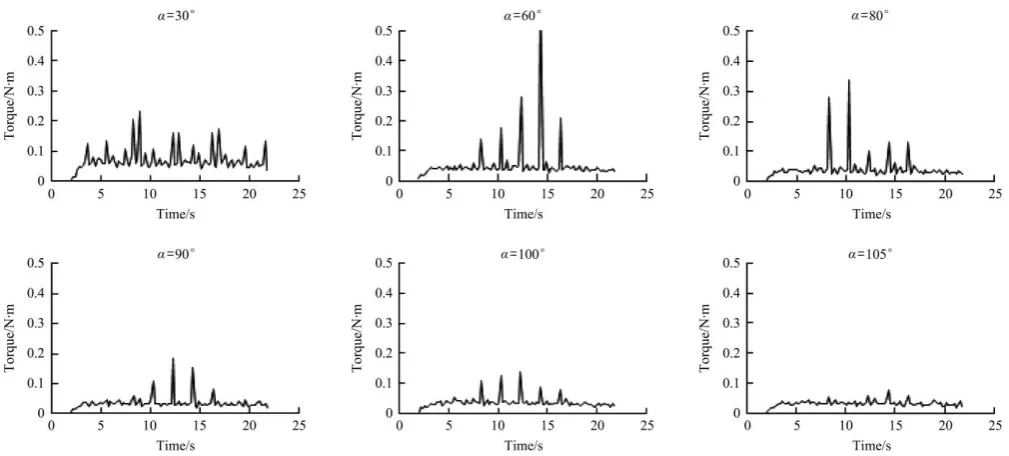
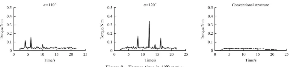
To investigate the effect of fertilizer-filling angle on the operation, different fertilizer-filling angles that range from 30°, 60°, 90°, and 120° are investigated (Figure 5). The torque-time relationship is analyzed for the roller.
Figure 5 Fertilizer-filling surface in different fertilizer-filling angle
Test conditions: the feed-roll length is set to the maximum value of 75 mm, and the fertilizer-contact angle is set to 125°, and the roller rotational speed is set to 90 deg/s (When the roller rotates slowly, the situation of forced is more likely to be unstable, and at a slower rotational speed, the force variation of the roller can be observed in more detail under the same simulation time step).
As shown in Figure 6, a model of the conventional machine is employed for comparison, and the related data of structure and shape can be referred to Figure 1a. In order to control the factors, the size of the roller is the same as the test model which design in the paper. There are a gap between the roller and the outer cover to simulate the discharge of fertilizer in driving layer, and there is no fertilizer-filling cavity, fertilizer-filling surface and fertilizer-delivery cavity. This model was applied in subsequent test in the paper.
Figure 6 Structure of traditional fluted-roller fertilizer applicator
The simulation results show that when the filling angle is about 105°, the average torque and maximum torque of the roller are at a relatively low level, and there is less sudden increase in torque (Table 1). When the fertilizer-filling angle is less than 90°, with the decrease of fertilizer-filling angle, the recirculation in the inner driving layer becomes worse. Meanwhile, the fertilizer particles tend to stay in the filling angle, which increases the probability of being squeezed and sheared by the roller, resulting in the sudden increase in torque. When the fertilizer-filling angle is greater than 90°, it is beneficial to the splitting of inner driving layer and forced layer, and when it is larger than 105°, the effect is gradually weakened. According to the numerical results given in Figures 7 and 8, the fertilizer-filling angle is set to 105°.
Table 1 Situation of force of the roller withdifferent α
α /(°)
Average torque /N·m
Maximum torque
/N·m The Sd. of torque
30 0.0725 0.233 0.0356
60 0.0536 0.597 0.0669
80 0.0436 0.339 0.0432
90 0.0372 0.184 0.0184
100 0.0369 0.138 0.0227
105 0.0332 0.074 0.0111
110 0.0351 0.161 0.0179
120 0.0393 0.344 0.0374
traditional 0.0209 0.030 0.0052
Figure 8 Torque-time in different α The simulation results show that the driving layer in the
traditional structure can be discharged smoothly through the gap and the drainage wheel runs smoothly. The average and maximum torque are 0.0209 N·m and 0.030 N·m, respectively. The Sd. is 0.0052. When the fertilizer-filling angle α is 105°, the best guiding effect of the inner driving layer can be achieved. Meanwhile, the performance parameters are at the optimal levels in each filling angle, they are: the average torque is 0.0332 N·m, the maximum torque is 0.074 N·m, and the Sd. is 0.0111. The data results are closest to the data of the traditional structure, which is the most conducive to the smooth operation of the roller.
4.2 Fertilizer-contact angle and Fertilizer-resistance angle
The fertilizer-filling angle β and the fertilizer-resistant angle δ are two key determining factors for the shape of the fertilizer-filling surface. The fertilizer-contact angle determines the span of the interaction between the inner driving layer and the forced layer. A series of single factor simulation tests are designed for determining these two factors.
The feed-roll length is set to 30 mm, and the fertilizer-filling angel is 105°, and the roller rotational speed of the roller is set to 360 deg/s (the faster the rotational speed is, the more obvious the instability of filling and discharging will be).
In the first step, the effects of different fertilizer-resistance angles δ on the full discharge of fertilizer is qualitatively analyzed. The fertilizer-contact angle is set to 125°, and the fixed fertilizer-filling angle is 105°, the fertilizer-resistant angles of 50°, 40°, 30° and 20° (Figure 9) are tested to observe whether there is fertilizers in the groove that are not discharged and re-enter the machine with roller (Table 2).
Figure 9 Structure of different fertilizer-resistant angle
Table 2 Working status of different fertilizer-resistant angle
δ/(°) 50 40 35 30 20
Whether Fully discharged no no yes yes yes It is found that, in the higher roller rotational speed state, when the fertilizer-resistance angle is greater than 35°, there will be that the fertilizer cannot be fully discharged. In order to ensure sufficiently discharging for fertilizer, δ should be selected to be no
more than 35°. For the condition of practical application, a gap between the critical and design values is needed to avoid the insufficient discharge of fertilizer, thus, δ is selected to be 30°.
In the next step, the fixed fertilizer-resistant angle is 30°, and the influence of different fertilizer-contact angles β on the filling of fertilizer is statistically observed. The fertilizer-contact angles are 50°, 75°, 100° and 125° (Figure 10). The amount of fertilizer within 10s is measured (Table 3).
Figure 10 Structure of different fertilizer-contact angle
Table 3 Mass of fertilization on 10 s of different fertilizer-contact angle
Β/(°) 50 75 80 85 90 100 125 Mass of fertilization
on 10 s/g 375.8 423.4 435.5 442.4 450.8 449.6 451.7 It is found that, in the higher roller rotational speed state, when the fertilizer-contact angle is less than 90°, there will be that the amount of fertilizer application decrease. The performance is similar, when the fertilizer-contact angle set between 90° to 125°. In order to ensure full filling of the fertilizer, β is selected to be no less than 90°. For the condition in practical application, a gap between the critical value and design value is maintained, thus, β is selected to be 100°.
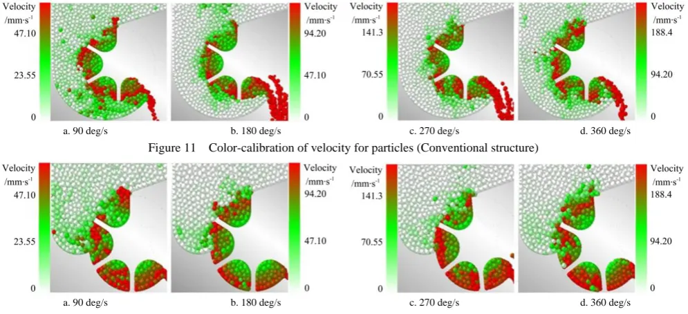
4.3 Color-calibration of velocity for particles
Since the structural parameters are determined (α=105°, β=100°, δ=30°), the status of movement of fertilizer particles is studied by the speed calibration method[24,34], and be compared with that in the conventional form (with the drive layer discharge) of the fluted-roller fertilizer applicator (Figure 6).
There are 4 groups of tests, in which the roller rotational speed is set to 90 deg/s, 180 deg/s, 270 deg/s, and 360 deg/s. The particle velocity v is calibrated in a white-green-red gradient color. In each of the tests, white indicates a velocity of 0 mm/s. In order to facilitate the comparison of the relative shapes at different speed levels, and to ensure good color discrimination at low speeds, the maximum speed vmax represented by red in each group is different,
from white-green-red. The simulation results at the 5.00 s time for the conventional and designed structural schemes are shown in Figures 11 and 12, respectively.
The results display that the conventional structural scheme allows the discharge in the driving layer, and the boundary between the driving layer and the forcing layer is not distinct. Moreover, the consistency of the thickness and the velocity of the particles is
not obvious, and the particle velocity of the driving layer is relatively random. These phenomena are caused the inaccuracy and in-precision of the fertilizer control. However, in the structural scheme proposed in this paper, when the forcing layer enters the fertilizer-delivery cavity, the boundary of the forced layer is clear and the groove is always filled, which is beneficial to improve the precision and accuracy of the fertilizer.
a. 90 deg/s b. 180 deg/s c. 270 deg/s d. 360 deg/s
Figure 11 Color-calibration of velocity for particles (Conventional structure)
a. 90 deg/s b. 180 deg/s c. 270 deg/s d. 360 deg/s
Figure 12 Color-calibration of velocity for particles (Designed structure)
5 Experiments
5.1 Performance test
The bench test was carried out on the test-bed to further compare the performance of conventional (Figure 6) and designed (Figure 4) structures, in which three kinds of composite fertilizers with different properties were applied, with the detailed information provided in Table 4.
The factor of roller rotational speed is set to 60 deg/s, 120 deg/s, 180 deg/s, 240 deg/s, 300 deg/s and 360 deg/s, and the feed-roll length is 30 mm. When the operation is stable, the amount of fertilizer application for 10 s is measured by an
electronic scale with the accuracy of 0.1 g. Each level of variable factors was repeated for 10 times. Statistical average mass of fertilizer Q* (g) and CV are given in Table 5. Correlation analysis was carried out for each group of roller rotational speeds and their corresponding average mass of fertilization, and a regression equation was established.
Table 4 Fertilizers for test and its parameter
YARA WANGU ISLAND Particle size distribution (>90%)/mm 1.5-4 2-3 3-4
Bulk density/g·mL-1 0.834 0.879 0.845
Average sliding friction angle/(°) 23.5 23.8 24.8
Table 5 Performance of fertilizer applicator
5-1 YARA Roller rotational speed
/deg·s-1
Average mass of fertilization of conventional/g
The CV of the mass before conventional/%
Average mass of fertilization of optimization/g
The CV of the mass after optimization/%
60 130.63 2.87 77.66 1.41
120 223.20 2.19 160.17 0.99
180 326.14 1.92 242.72 0.43
240 440.13 2.11 326.37 0.56
300 553.84 1.84 408.88 0.34
360 658.60 1.72 493.27 0.45
5-2 WANGU Roller rotational speed
/deg·s-1
Average mass of fertilization of conventional/g
The CV of the mass before conventional/%
Average mass of fertilization of optimization/g
The CV of the mass after optimization/%
60 102.33 1.15 83.13 1.67
120 191.77 3.13 159.04 0.91
180 294.14 2.25 235.51 0.71
240 419.63 2.04 312.78 0.93
300 536.92 1.50 391.12 0.77
5-3 ISLAND Roller rotational speed
/deg·s-1
Average mass of fertilization of conventional/g
The CV of the mass before conventional/%
Average mass of fertilization of optimization/g
The CV of the mass after optimization/%
60 96.90 2.05 76.11 1.72
120 202.86 1.93 152.82 0.94
180 303.75 1.92 228.27 0.56
240 403.47 2.10 305.50 0.46
300 496.53 1.63 381.93 0.70
360 583.39 1.91 457.24 0.70
It can be seen in Table 5 that in the designed device the CV of fertilizers is smaller with different types of fertilizers and rotational speeds than those in the conventional structure, which demonstrates that the precision of the amount of fertilizer application is improved with the designed structure.
Via the regression analysis, a series of regression equations for the three fertilizers in the machine of conventional structure (Figure 6) are as follows:
YARA: y = 1.809x + 7.5968; WANGU: y = 1.8019x – 11.747; ISLAND: y = 1.6369x + 3.4814.
The squared of the correlation coefficient R2 between the average mass of fertilization and the roller rotational speed is YARA: 0.998; WANGU: 0.997; ISLAND: 0.999.
The regression equations for the fertilizers in the improved device in this paper are as follows:
YARA: y = 1.3741x – 3.1811; WANGU: y = 1.2981x + 2.3289; ISLAND: y = 1.2715x – 0.0229.
The square of the correlation coefficient R2 between the average mass of fertilization and the roller rotational speed is YARA: 0.999; WANGU: 0.999; ISLAND: 1.000 (Figure 13).
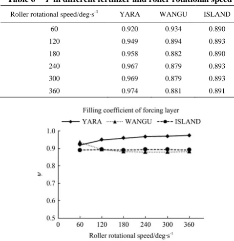
Figure 13 Mass of fertilizer-rotational speed of roll Referring to Equation (5), Ψ of forced layer in the designed
structure is calculated in Table 6. In the designed structure of machine, when the rotational speed of roller is greater than 120 deg/s, Ψ of three fertilizers is nearly unchanged (Figure 14).
Table 6 Ψ in different fertilizer and roller rotational speed
Roller rotational speed/deg·s-1 YARA WANGU ISLAND
60 0.920 0.934 0.890
120 0.949 0.894 0.893
180 0.958 0.882 0.890
240 0.967 0.879 0.893
300 0.969 0.879 0.893
360 0.974 0.881 0.891
Figure 14 Ψ in different fertilizer and roller rotational speed
5.2 Test of fertilizer particle motion
The motion state of the fertilizer particles was further observed by high-speed photography, to explore to verify the rationality of the designed machine.
The device is covered by a top cover made by PMMA. A high-speed camera, Photron FASTCAM, is used at the frame rate of 500 fps.
In the test, 4 groups of high-speed images are taken under 4 roller rotational speeds of the roller as factor level (90 deg/s, 180 deg/s, 270 deg/s, 360 deg/s). At each level of rotational speed, 5 groups of samples are from the image at the time of 1.00 s, 2.00 s, 3.00 s, 4.00 s, 5.00 s.
Two factors named Pos (position) and Dta (distance) are analyzed based on the images. Pos is defined as the circumferential position of the outer circle of the roller, and Dta as the distance from the outer circle of the roller in the axial direction. The fertilizer particles are sampled and tracked at each roller rotational speed according to the following. The position are measured based on the center of each particles’ approximately circle.
Item 1: Dta is set as 0±0.5 mm (That is, the particles in driving layer are the closest to the outer circle of the roller), and set the area that 30°±5°, 60°±5°, 90°±5°, 120°±5°, 150°±5° from the fertilizer outlet (Figure15a) as 5 levels of Pos (Pos1~Pos5).
a. Item 1 b. Item 2 Figure 15 Examples of particles selecting
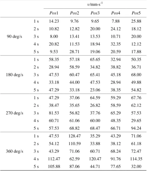
The displacement x of a particle is measured by a short time position tracking for the particle, and the average velocity v of the particle in a time period (Table 7-Table 8) is calculated.
The variance analysis of two factors with repeated observations is used. Item 1: For Pos, F is 0.872 that is less than critical level. sig. (significant level) is 0.484. For roller rotational speed, F is 39.84 which far greater than the critical level, and sig. is 0.000. Item 2: For Dta and roller rotational speed, F are 33.265 and 24.537, which all far great than the critical level, and the sig. is 0.000 and 0.000 (Table 9).
It shows that the average violence of the particles of driving layer is enlarged with the increase of the roller rotational speed, and reduced with the increase of the distance of the outer circle of roller. The average violence of the particles in driving layer is independent of the circumferential position of the outer circle of roller.
Using Duncan’s Method, v (of particle) shows obvious difference by the factor level of Dta1, Dta2, and Dta3. However, there is no significant difference in v (of particle) by the factor level of Dta4 and Dta5. For the particles outside the excircle of the roller from 6mm, the values of v are very small. It can be considered that the effective driving layer is concentrated within 6mm of the outer circle of roller. But the absolute boundary of driving layer does not exist.
Table 7 Average velocity v of particles (item 1)
v/mm·s-1
Pos1 Pos2 Pos3 Pos4 Pos5
90 deg/s
1 s 14.23 9.76 9.65 7.88 25.88 2 s 10.82 12.82 20.00 24.12 18.12 3 s 8.00 13.41 13.53 10.71 20.00 4 s 20.82 11.53 18.94 32.35 12.12 5 s 9.53 28.71 19.06 20.59 17.88
180 deg/s
1 s 58.35 57.18 65.65 32.94 50.35 2 s 28.94 58.59 34.82 38.82 36.71 3 s 47.53 60.47 65.41 45.18 68.00 4 s 33.18 44.00 47.53 28.94 49.88 5 s 47.29 33.18 23.06 38.35 54.82
270 deg/s
1 s 47.29 37.06 64.59 59.29 67.76 2 s 38.47 35.65 26.82 58.59 62.12 3 s 81.53 56.82 37.76 65.29 57.53 4 s 60.71 61.06 60.00 48.35 29.65 5 s 57.53 68.82 68.47 66.71 94.24
360 deg/s
1 s 47.53 128.47 35.29 43.29 71.06 2 s 54.12 110.59 33.88 38.12 61.18 3 s 43.29 71.06 60.71 68.24 72.47 4 s 112.47 62.59 120.47 91.76 114.35 5 s 105.88 87.06 44.71 77.65 32.00
Table 8 Average velocity v of particles (item 2)
v/mm·s-1
Dta1 Dta2 Dta3 Dta4 Dta5
90 deg/s
1 s 14.23 11.88 6.94 4.12 2.71 2 s 10.82 12.00 10.47 9.18 3.76 3 s 8.00 10.71 11.06 6.00 3.76 4 s 20.82 9.65 8.94 4.82 1.29 5 s 9.53 18.71 10.24 4.00 5.65
180 deg/s
1 s 48.94 31.53 15.06 13.65 8.00 2 s 40.71 26.35 15.76 15.53 3.53 3 s 57.65 40.94 26.59 2.82 2.12 4 s 44.47 33.41 10.35 6.82 5.41 5 s 28.71 13.65 12.71 5.88 4.47
270 deg/s
1 s 59.29 41.65 34.24 7.41 0.71 2 s 36.35 20.82 16.59 5.65 4.24 3 s 58.24 31.06 18.71 7.41 6.00 4 s 63.18 41.65 25.76 12.71 6.35 5 s 70.24 44.12 40.59 13.41 1.06
360 deg/s
1 s 132.24 78.12 48.00 24.94 19.76 2 s 109.65 66.35 13.18 8.94 6.59 3 s 50.82 41.41 13.65 11.29 9.88 4 s 123.76 60.71 33.88 24.00 16.94 5 s 84.24 68.24 33.41 19.29 13.65
Table 9 Analysis of variance
Source SS Df MS F sig.
Pos 1188.012 4 297.003 0.872 0.484
speed 40662.946 3 13554.3 39.84 0.000* error 31331.455 92 340.559
Total 73182.413 99
Dta 30116.241 4 7529.06 33.265 0.000* speed 16660.790 3 5553.59 24.537 0.000*
error 20822.989 92 226.337 Total 67600.021 99
Note: * means highly significant (p<0.01).
Within 6 mm of the outer circle, the relationship between v and Dta from all levels of roller rotational speeds is not linear at all. R2 values of them are no larger than 0.978, and the worst is only –0.883.
Neglecting the factor Pos in Item 1, 4 groups of 25 samples per group from 4 levels of roller rotational speed are analyzed by statistical description (Table 10).
Table 10 Statistical description of v in Item1
Rotational speed of the roller ω/deg·s-1
90 180 270 360
Mean/mm·s-1 16.42 45.97 56.48 71.53
Std. Deviation 6.64 12.82 15.89 29.90
CV 0.41 0.28 0.28 0.42
It can be seen in Table 10 that the values of Sd. and CV of v are always high, which indicate the obvious instability of the particles with the same distance of excircle at each roller rotational speed. Meanwhile, it is hardly to fit the linear relationship between the average velocity of particles and the roller rotational speed, and R2 of them is 0.951.
6 Discussion
the driving layer is not conducive to the precision control in VRF. It is noticed that one of the main reasons for the inaccuracy of the conventional machine is the instability of the driving layer. The velocity differences of particles are too large, which lead to a decrease in the precision of the amount of fertilizer application. The overall velocity of the driving layer particles increases with the increase of roller rotational speed, and decreases with the increase of the outer circle distance of roller. It is also found that the overall velocity of the driving layer particles is independent of the circumferential position of the driving layer where the particles are located. However, it is difficult to find the linear correlation relationship in the thickness of the driving layer, and the average velocity of particles is also nonlinearly related to the increase of roller rotational speed.
After the improvement of the structure, the filling coefficient of forcing layer is able to remain stable with the change of the roller rotational speed except at the low rotational speed of roller (60 deg /s). Thus, the stability of the filling coefficient of forcing layer is another reason for ensuring the accuracy of the mass of fertilization. It is noted that the precision of the mass of fertilization at low-speed of roller rotational (60 deg/s) is affected by the shape of fluted-roller. Therefore, it is not recommended to use the fertilizer wheel to work at low roller rotational speed. When the amount of fertilizer is low, feed-roll length can be adjusted to achieve variable adjustment. Further study is needed on the precision of the amount of fertilizer application at low roller rotational speed.
7 Conclusions
In this study, the effects of forced layer filling characteristics and driving layer characteristics on the amount of fertilizer application were numerically and experimentally studied, and the precision and accuracy of the amount of fertilizer application were improved by the designed machine with properly determined structural parameters.
In this study, the analysis declares that the fertilizer-filling cavity can improve the stability of the filling in the forced layer, reduce the influence of precision and accuracy of fertilizer applicator by the filling of fertilizer; the fertilizer-filling surface can drive the flow guiding, and block the discharge of the driving layer, and even eliminate the influence of precision and accuracy of fertilizer applicator by the instability of the driving layer; and the fertilizer-conveying cavity can further enhance the accuracy of the amount of fertilizer in the forced layer and achieve stable delivery in synchronization with the rotation of roller, the influence on precision of fertilizer application by the unsynchronization was further reduced.
The parameters of α, β and δ were determined based on EDEM. When α is set to 105°, the performance of the filling and diversion guided of the inner driving layer is the best, and the operation of roller is the most smooth; when β is set to 100°, the inner driving layer can ensure the full filling of the fertilizer in grooves, and a sufficient fertilizer-delivery cavity is ensured; when δ is set to 30°, sufficient discharge of fertilizer is ensured, and a sufficient fertilizer-resistant angle is reserved.
The performance experiment shows that, the precision of the amount of fertilizer application was improved in most cases under different speed conditions, and the CV was further reduced. The three types of fertilizers had a CV >1% only in the low-speed of roller rotation (60 deg/s), and <1% in all other cases. In the conventional machine, the CV is generally between 1.5% and 3.0%,
except for a few cases. The accuracy was analyzed from the linear relationship. R2 of the designed machine was not less than 0.999, while the R2 values of the first three fertilizers were improved to be 0.998, 0.997, and 0.999, respectively. It is more conducive to the precise control of VRF.
Acknowledgements
We acknowledge that this research was financially supported by National Key Research Program Project (No.2016YFD0200600,
2016YFD0200606, 2018YFD0200700, 2018YFD0200704,
2017YFD0700500, 2017YFD0700503). We would also like to thank the anonymous reviewers for their critical comments and suggestions for improving the manuscript.
[References]
[1] Luo X W, Ou Y G,Zang Y, Ma X, Liao Q X, Zhang Y L. Thoughts on accelerating the development of agricultural mechanization in China. Agricultural Engineering, 2011; 1(4): 1–8+56. (in Chinese)
[2] Luo X W, Liao J, Hu L, Zang Y, Zhou Z Y. Improving agricultural mechanization level to promote agricultural sustainable development. Transactions of the CSAE, 2016; 32(1): 1–11. (in Chinese)
[3] Koch B, Khosla R, Frasier W M, Westfall D G, Inman D. Economic Feasibility of Variable-Rate Nitrogen Application Utilizing Site-Specific Management Zones. Agronomy Journal, 2004; 96(6): 1572–1580. [4] Wang H Y, Zhou J M. Calculation of real fertilizer use efficiency and
discussion on fertilization strategies. Acta Pedologica Sinica, 2014; 51(2): 216–225. (in Chinese)
[5] Yu Y, Li C J, Shi L G, Huai H J, Qin X Y. Studies on domestic and overseas in research progress of agricultural information technologies. Computer and Computing Technologies in Agriculture VII—Proceedings of 7th IFIP WG 5.14 International Conference, Part Ⅱ.China-EU Center for Information & Communication Technologies in Agriculture (CICTA), 2013; pp.215–228.
[6] Yang L W, Chen L S, Zhang J Y, Liu H J, Sun Z H, Sun H. Fertilizer sowing simulation of a variable-rate fertilizer applicator based on EDEM. IFAC-PapersOnLine, 2018; 51(17): 418–423.
[7] Shi Y Y, Hu Z C, Wang X C, Odhiambo M O, Sun G X. Fertilization strategy and application model using a centrifugal variable-rate fertilizer spreader. Int J Agric & Biol Eng, 2018; 11(6): 41–48.
[8] Chen C, He P X, Zhang J J, Li X X, Ren Z Y, Zhao J, et al. A fixed-amount and variable-rate fertilizer applicator based on pulse width modulation. Computers and Electronics in Agriculture, 2018; 148: 330–336. [9] Camacho-Tamayo J H, Barbosa A M, Perez N M, Leiva F R, Rodriguez G A. Operational Characteristics of four metering system for agricultural fertilizers and amendments. Eng. Agríc., Jaboticabal, 2009; 29(4): 605–613.
[10] Ding S P, Bai L, Yao Y X, Yue B, Fu Z L, Zheng Z Q, et al. Discrete element modelling (DEM) of fertilizer dual-banding with adjustable rates. Computers and Electronics in Agriculture, 2018; 152: 32–39.
[11] Su N, Xu T S, Song L T, Wang R J, Wei Y Y. Variable rate fertilization system with adjustable active feed-roll length. Int J Agric & Biol Eng, 2015; 8(4): 19–26.
[12] Jafari M, Hemmat A, Sadeghi M. Development and performance assessment of a DC electric variable-rate controller for use on grain drills. Computers and Electronics in Agriculture, 2010; 73(1): 56–65.
[13] Chattha H S, Zaman Q U, Chang Y K, Read S, Schumann A W, Brewster G R, et al. Variable rate spreader for real-time spot-application of granular fertilizer in wild blueberry. Computers and Electronics in Agriculture, 2014; 100: 70–78.
[14] Liang C Y, Lü P, Ji J W, Wang X. Optimization of PID parameters for electro-hydraulic variable rate fertilization system based on genetic Algorithm. Transactions of the CSAM, 2010; 41(7): 157–162. (in Chinese) [15] Shao L M, Wang X, Niu X Y, Qian D P. Design and experiment on PLC
control system of variable rate fertilize. Transactions of the CSAM, 2007; 28(11): 84–87. (in Chinese)
parameters regulation sequence for fertilization. Transactions of the CSAE, 2011; 27(11): 134–139. (in Chinese)
[18] Lv H, Yu J Q, Fu H. Simulation of the operation of a fertilizer spreader based on an outer groove wheel using a discrete element method. Mathematical and Computer Modelling, 2013; 58(3-4): 842–851.
[19] Huang Y X, Wang B T, Yao Y X, Ding S P, Zhang J C, Zhu R X. Parameter optimization of fluted-roller meter using discrete element method. Int J Agric & Biol Eng, 2018; 11(6): 65–72.
[20] Shi Y Y, Chen M, Wang X C, ODHIAMBO M O, Zhang Y N, Ding W M. Analysis and experiment of fertilizing performance for precision fertilizer applicator in rice and wheat fields. Transactions of the CSAM, 2017; 48(7): 97–103. (in Chinese)
[21] Fu Z T, Dong Y H, Zhang L X, Yang H, Wang J Q, Li X X. Design and simulation of automatic fertilizing machine for greenhouse. Transactions of the CSAE, 2017; 33(Supp.1): 335–342. (in Chinese)
[22] Zhang T, Liu F, Liu Y Q, Zhao M Q, Zhang S, Li N, et al. Discrete element simulation of outer groove wheel type fertilizer discharging device capacity analysis. Journal of Agricultural Mechanization Research, 2015; 37(9): 198–201. (in Chinese)
[23] Li K, Zhang L X, Zhang L P, Chu S Z, Qi X M, Qian Y, et al. Design and experiment of bivariate fertilizer. Journal of Gansu agricultural university, 2016; 51(8): 128–133. (in Chinese)
[24] Wang B T, Bai L, Ding S P, Yao Y X, Huang Y X, Zhu R X. Simulation and experimental study on impact of fluted-roller fertilizer key parameters on fertilizer amount. Journal of Chinese Agricultural Mechanization, 2017; 38(10): 1–6, 23. (in Chinese)
[25] Chinese Academy of Agricultural Mechanization. Agricultural machinery design manual. China Agricultural Science and Technology Press, 2007. (in Chinese)
[26] Kara M, Bayhan A K, Ozsert I, Yildirim Y. Performance of fluted roll
metering devices in seed drills with ammonium sulphate and diammonium phosphate. Applied engineering in agriculture, 2010; 26(2): 197–201. [27] Qi X Y, Zhou Z Y, Yang C, Luo X W, Gu X Y, Zang Y, et al. Design
and experiment of key parts of pneumatic variable-rate fertilizer applicator for rice production. Transactions of the CSAE, 2016; 32(6): 20–26. (in Chinese)
[28] Chen X F, Luo X W, Wang Z M, Zhang M H, Hu L, Yang W W, et al. Design and experiment of a fertilizer distribution apparatus with double-level screws. Transactions of the CSAE, 2015; 31(3): 10–16. (in Chinese)
[29] Kin Y J, Kim H J, Yong R J, Jang T S. Development of a Variable Rate Granule Applicator for Environment-Friendly Precision Agriculture (III)-Analysis of Pneumatic Conveying System and Improvement of Fertilizer Application Uniformity. Journal of Biosystems Engineering, 2006; 31(119): 482–488.
[30] Ma Z, Li Y M, Xu L Z. Summarize of particle movements research in agricultural engineering realm. Transactions of CSAM, 2013; 44(2): 22–29. (in Chinese)
[31] Horabik J, Molenda M. Parameters and contact models for DEM simulations of agricultural granular materials: A review. Biosystems Engineering, 2016; 147: 206–225.
[32] Yang Z, Zhu Q C, Sun J F, Chen Z C, Zhang Z W. Study on the performance of fluted roller fertilizer distributor based on EDEM and 3D printing. Journal of Agricultural Mechanization Research, 2018; 40(5): 175–180. (in Chinese)
[33] Lv H. A new kind of method for optimized design of outer groove-wheel fertilizer apparatuses. Changchun: Jilin University, 2014. (in Chinese) [34] You Y, Zhao Y Z. Discrete element modelling of ellipsoidal particles