Using variable spray angle fan nozzle on long spray booms
Hamid Reza Ghasemzadeh
1*, Daniel D. Humburg
2(1 Biosystems Engineering Department, University of Tabriz, P. O. Box 51666- 14776, Tabriz, 51666, I. R. Iran;
2 Agricultural and Biosystems Engineering Department, P. O. Box 2120, Brookings, SD 57007, USA)
Abstract: A new-concept of using variable spray angle fan spray nozzle in conjunction with pulse width modulation technique was proposed for compensation of the effects of spray boom vibration on chemical application rate and pattern. A review of literature regarding techniques used to diminish the effects of long spray booms dynamic behavior on uniformity of spray application reveals that the research work so far has mostly involved boom positioning, vibration analysis, mathematical modeling and monitoring of boom dynamic behavior, in the hope of finding the ways to attenuate vibration through improving the design of boom structure, suspension, and control systems. The present article puts forward the idea of using Variable Spray Angle Fan Spray Nozzle (VSAFSN) along with pulse width modulation (PWM) technique to maintain constant spray coverage, hence, uniformity of spray application. TEEJET-XR11002 Nozzle was used and preliminary experiments were carried out to study the feasibility of the proposed concept. Spray pressure range of 55 kPa to 490 kPa, was used to vary spray angle from 78 to 160 degrees. Results showed that the spray maintained its almost normal distribution pattern within full range of spray angle. Relationships between spray angle (y) and operating pressure (x) was found as y=0.1495x-90.851, R2=0.7953, and, between nozzle flow rate (y) and spray angle (x) was found as
y=8.3824x-387.13, R2=0.8712.
Keywords: dynamic, nozzle, pulse width modulation, uniformity
Citation: Ghasemzadeh, H. R., and D. D. Humburg. 2016. Using variable spray angle fan nozzle on long spray booms. Agric Eng Int: CIGR Journal, 18(1):82-90.
1 Introduction
1Apart from huge costs associated with the use of
chemicals in the farms, there are some evidences that
long term exposure to pesticides may cause
neurodegenerative diseases such as dementia;
Alzheimer’s in particular, and Parkinson (Streenland et
al., 2014; Thany et al., 2013). On the other hand, ever
increasing demands by farmers for better machinery
(Chaplin and Wu, 1989), including longer spray booms
have made manufacturers to build giant booms to help
farmers in terms of increasing their working rates to
overcome timeliness problems.
Application of minimum amount of liquid chemicals
efficiently and maintaining a uniformity of spray
coverage, has long been a challenging issue in crop
Received date: 2015-09-11 Accepted date: 2016-01-06
*Corresponding author: Hamid Reza Ghasemzadeh, University of Tabriz, Biosystems Engineering Department, Tabriz 51666-14776, Iran, [email protected]. Phone: +98 914 313 5277.
protection operations. On the other hand, the sizes of
the machines that deal with spraying chemicals over the
large areas of the land have been increased tremendously
and sprayers with 46 m long booms are not uncommon
(Anon, 1997).
Boom moment of inertia increases as boom length
increases and the vertical movement of the boom results
in non-uniform spray coverage (Nalavade et al., 2008).
This non-uniformity may range from 0 to 800%
(Anthonis et al.,2005).
Apart from excessive vertical boom movements, the
operator may need to reposition either sides of the boom,
when the machine is travelling on slopes, in such a way
that they may not be aligned (Bjørnsson et al.,2013) and
this may require some additional precision which
increases the work load of an operator.
Despite of tremendous efforts by researchers around
the world to implement a kind of active spray boom
position control system (Sartori et al., 2002), owing to
coverage have not yet been overcome. It seems that in
the long run Altek carbon fiber booms (Vogt, 2013) can
be a better solution in terms of reducing the time of
response of the boom to control commands due to their
light weight hence lower inertia. Another approache, i.
e., isolation of the sprayer boom from the chassis
vibration in the hope of controlling the violent dynamic
behavior of boom has received more attention (Chaplin
and Wu, 1989). Chaplin and Wu (1989) developed a
computer model to simulate the movement of a sprayer
boom and investigated the effect of tank liquid volume
and tire inflation pressure on dynamic behavior of a spray
boom. They concluded that spray distribution tends to
be more uneven when the amount of liquid in the tank
decreases.
Most of the research carried out during the last
decade regarding relationship between spray boom
dynamics and spray distribution uniformity was
concentrated on analyzing and modeling the dynamic
behavior of the long spray booms and their relation with
spray pattern, and the validation of models through either
workshop or field experiments (Clijmans et al.,1996;
Clijmans et al.,2000a; Clijmans et al.,2000b; Clijmans
et al.,2001; Jeon et al.,2003; Langenakcns et al.,1993).
The core idea during these works was to develop
some techniques to better understand system behavior
and identify those parameters that have the most control
on the system dynamic behavior with the aim of
establishing well defined standards for laboratory testing
of the machines and avoiding the laborious field
experiments.
The amount of works faded out by the early years of
current decade as far as the literature of the subject is
concerned, since these methods seemed to have become
sufficiently mature (Parloo et al., 2003; Jeon et al.,2004).
Instead, interests were shifted towards optimization and
redesigning of the components as well as developing
better, and in some cases smart control systems for spray
boom behavior control (Anthonis et al., 2005; Bjørnsson
et al.,2013).
On the other hand, research works are underway to
study the key parameters of nozzles affecting the droplet
size distribution (Cock et al., 2014) and to develop the
nozzles with the capability of variable rate application
(Womac and Bui, 2002; Lang, 2013).
The common goal of all works presented above was
to apply the minimum amount of liquids uniformly with
appropriate size of droplets necessary to destroy pests, in
the meantime, avoiding undesirable skips and/or overlaps.
This article attempts to develop an idea of using variable
spray angle fan spray nozzle (VSAFSN) with modulated
pulse width (PWM) to overcome the problems imposed
by vibration of long spray booms resulting in
non-uniform spray pattern while employing variable rate
technology (VRT).
2
Materials and methods
To maintain the uniformity of spray while the spray
boom is oscillating, two possibilities may be considered:
first, real time controlling of the angle of angled flat fan
nozzles (AFFN) that can be directed forward or
backwards, and second, using a real time controlled
variable spray angle fan spray nozzles (VSAFSN). It
might not be necessary to control all the nozzles along the
boom, but those nozzles that contribute to spray
non-uniformity at either ends of the boom.
2.1 Geometrical considerations
The geometry as well as the equations for
calculating the spray distribution was proposed by
Chaplin and Wu (1989) as follows:
Figure1 Geometry of spray distribution (Chaplin and
( ) (1) ( ) (2)
Where:
2.1.1 he effect of boom inclination on transversal shift of
the spray coverage (TSSC)
Nozzles with 80 and 110 degrees of spray angles are
the most common that are used in farming practices.
Suggested minimum spray heights for aforementioned
nozzles are 0.8 and 0.6 m respectively for nozzle spacing
of 75 cm (Anon, 2015). If the length of the boom
considered to be within the range of 27 to 51 m, and the
range of boom tip vertical displacement to be within the
range of -0.45 to +0.45m from its horizontal position
while operating on the smooth track (Jeon et al.,2003a),
then, the range of boom angle can be calculated as
follows:
For 27m boom:
(3a)
Similarly, for 51m boom:
(3b)
For 80 degrees spray angle nozzle at 0.8m spray
height on 27 m long boom, the range of variation for for outermost nozzle due to boom tip vertical
displacement can be calculated from Equations (1) and
(2) as follows:
For
( ) ( )
( ) ( ) i.e.
(4) And, for
( ) ( )
( ) ( )
i.e.
(5)
From Equations (4) and (5), a transversal shift for X1
and X2 ( ) can be found as:
For :
( ) (6)
For : (7)
Similarly, for 110 degree spray angle nozzle at 0.6m
spray height on 27 m long boom the range of variation for for outermost nozzle due to boom tip vertical
displacement can be calculated from Equations (1) and
(2) as follows:
( ) ( )
( ) ( ) i.e.
(8) And, for
( ) ( )
( ) ( ) i.e.
(9)
From Equations (8) and (9), a transversal shift for
and for110 degree spray angle nozzle at 0.6m
spray height on 27 m long boom ( ) can be found
as:
For :
( ) (10)
For : (11)
2.1.2 The effect of boom end height variation on the
spray coverage
Under the same conditions mentioned already for the
boom, the normal spray coverage (NSC) for the nozzles
at suggested height can be written as:
(12)
For 80 degree nozzle, range of spray coverage
variations ( ) due to boom oscillation can be
calculated from Equations (4) and (5) as follows:
( ) ( )
i.e.
(14)
This means that the spray coverage for 80 degrees
nozzle would vary from 0.58m to 2.10m, if boom tip
vertical displacement varies from -0.45m to +0.45m.
For 110 degree nozzle, the range of spray coverage
variations ( ) due to boom oscillation can be
calculated from Equation (8) and (9) as follows:
( ) ( )
i.e.
(15)
This means that the spray coverage for 110 degree
nozzle would vary from 0.43m to 2.99m if boom tip
vertical displacement varies from -0.45m to +0.45m.
The deviation of spray coverage (DSC) from normal
spray coverage due to boom vertical oscillations for the
80 degrees nozzle can be deduced from Equations (14) as
below:
[ ] (16)
Similarly, the deviation of spray coverage (DSC)
from normal spray coverage due to boom vertical
oscillations for the 110 degrees nozzle can be deduced
from Equation (15) as below:
[ ] (17)
To correct this situation, i.e. to keep the spray
coverage constant during boom vertical oscillations, two
approaches may be envisaged: a) varying the angle of
nozzle forward or backward from its vertical position, or,
b) varying the angle of spray. The implications of these
approaches are discussed below.
a) he range of the angular variation of the AFFN
forward (or backward) from its vertical position
(RAV) if the spray coverage is to be kept constant
while boom is oscillating:
(18)
(19)
b) he range of spray angle variation (RSAV) required in
VSAFSN if the spray coverage is to be kept constant
while boom is oscillating:
( )
( ) i.e.
(20)
And
( )
( ) i.e.
(21)
As one can easily conclude from Equations (18) and
(19), approach (a) is one-sided approach, i.e., it might
only be effective when the boom preset height decreases;
it could not accommodate the increase in boom preset
height. Therefore, the rest of this article would discuss
the technical requirements and implications that may
arise from the deployment of approach (b).
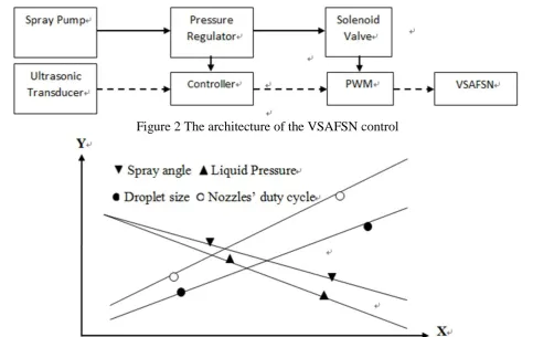
2.2 The architecture and operation of the VSAFSN
control system
Figures 2 and 3 show the architecture of the
proposed system and the changing trends of the
dependent variables with nozzle height respectively. As
can be seen in Figure 2, an ultrasonic transducer monitors
the height of the nozzle from crop canopy. The
amplitude of the output signal from the transducer which
is input to controller varies in proportion with the nozzle
height. The controller sends two input signals; one to
pressure regulator to adjust the liquid pressure, and the
cycle of the spray solenoid valve. This means that the
spray pressure, hence, spray angle, would change
simultaneously while maintaining the desired spray
volume and coverage on crop canopy.
Fi
gure 3 shows the anticipated changing trends ofthe spray angle, liquid pressure, droplet size, and nozzle
duty cycle with nozzle height. As the height of the
nozzle increases/decreases, the spray pressure, hence
spray angle decreases/increases. Decrease/increase in
spray pressure results in increase/decrease in droplet size
(Grisso et al., 2013). Since the spray rate (GPM) is also
dependent on spray pressure, the duty cycle of the nozzle
increases/decreases to compensate for the change in rate
of spray.
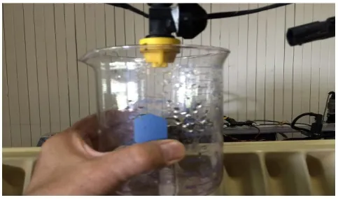
2.3 Experiments
To find out how the outcome of the idea might look
like some preliminary experiments were carried out.
TEEJET-XR11002 nozzle was examined using Sprayer
Nozzle Testing and Calibration facility based in
Agricultural and Biosystems Engineering department
workshop of South Dakota State University as shown in
Figure 4 Shown in the figure are
Note: Shown in the figure are collectors mounted on a swing table, test nozzles, and pressure gauge
Figure 4 Sprayer nozzle testing and calibration facility
To cover the spray angle range of 78 to 160 degrees
(see Equation 13), the spray pressure was varied from 55
Figure 2 The architecture of the VSAFSN control
to 490 kPa. Spray angle was read directly from properly
waterproofed paper protractor as shown in Figure 5.
Figure 5 Waterproof paper protractor
3 Results and discussion
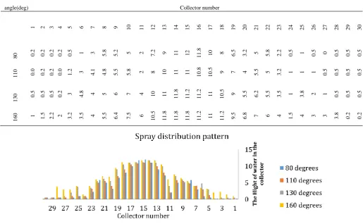
As mentioned in section 2.3 to provide spray
distribution pattern for spray angles of interest, namely, 80,
110, 130, and 160 degrees, spray pump was switched on
and spray pressure was set in such a way that a desired
spray angle was achieved. The collectors mounted on the
test table were then exposed to water spray until the middle
collectors were almost full. The height of the water in
each collector was read. As is shown in Figure 6 below,
the spray maintained its almost normal distribution pattern
within full range of spray angle.
The amount of water sprayed at different spray angles
were collected for 20 seconds followed by the calculation
of flow rates (Table 2 and Figure 7). Data from Table 2
were used to find “spray angle/operating pressure”, and “spray angle/nozzle flow rate” relationships.
Table 2 Nozzle flow rates at different operating pressures and spray angles
Operating Pressure (x)*, kPa Spray Angle (y*
or x**), deg Flow rate (y**), mL/min
55 80 375
83 110 450
152 130 600
490 160 1050
Note: *Relationship between spray angle (y) and operating pressure (x):
**Relationship between nozzle flow rate (y) and spray angle (x) was found as
Table 1 Spray distribution data: showing the height of water in each collector for different spray angles
Spray
angle(deg) Collector number
1 2 3 4 5 6 7 8 9 10 11 12 13 14 15 16 17 18 19 20 21 22 23 24 25 26 27 28 29 30
80 0.2 0.2 0.2 0.2 0.5 1 3 5.8 5.2 5 2 7.2 9 11 12 11.8 10 8 6.5 3.2 5 5.8 2.2 0.5 1 0.5 0 0.5 0.5 0.5
110 0.0 0.2 0.2 0.0 1.2 3 4.1 4.8 5.5 5.8 2 8 10 11 11 10.8 10.5 9 7 4 5.5 5 3.2 1 1 1 0.5 0.5 0.5 0.5
130 0.5 0.5 0.5 0.2
3 4.8 4 5 6 7 4 10 11
11.8 11.2 11.2 11 10.5 9 5.5 6.2 5.5 3.5 1 3.8 2 1 0.5 0.5 0.5
160 1 1.5 2.2 2 3.2 3.5 4 5.5 6.4 7.5 6 10.5 11.8 11.8 11.8 11.2 11 11.2 9.5 6.8 7 6 4 1.5 4 3 3 3.8 0.2 0.2
Figure 7 Nozzle flow rate measurement
To examine the adequacy of the VSAFSN system it
is necessary to conduct extensive lab tests in the first
place including step response, frequency response,
droplet size distribution, and uniformity of spray
coverage before implementation of large scale field tests.
It is anticipated that maintaining uniform spray
coverage at different nozzle heights by varying spray
angle, increase in droplet size will result due to lower
spray pressure (see Figure 3), reducing susceptibility of
spray to wind drift.
As can be seen in Table 2, the flow rate of the spray
decreased as spray angle decreased; this was in agreement
with the results obtained by other researchers (Martin,
2013). Therefore, it can be expected that the amount of
sprayed chemical would vary at different nozzle heights.
This can be overcome through PWM; increasing the duty
cycle of a nozzle (percentage of time that a solenoid
operated nozzle would remain open during one cycle of
operation or duty) as its height increases (see Figures 2
and 3). The main obstacles that must be overcome are
the operational pressure/spray angle, spray angle/spray
coverage, and operational pressure/spray flow rate
non-linear relationships. This may require a software to
send appropriate commands to pressure control valve as
well as PWM to compensate the nonlinearity.
It may also be possible to limit the normal range of
PWM duty cycle within say 25% to 75% in such a way
that at lowest height duty cycle be set for 25% while at
highest nozzle position the duty cycle of the nozzle be set
for 75%; this would allow for incorporating Variable Rate
Application (Lang, 2013) within full range of PWM
cycles, i.e. 0 to 100%.
The limitations that may encounter in practice can
include time of response of the valves and nozzles as well
as the performance of the system at high travel speeds.
4 Conclusions
rends towards achieving higher work rates, hence,
longer spray booms and precision continues in chemical
application operations and mechanical complexity of the
systems increases.
Simulation methods and modelling of dynamic
behavior of the long spray booms seem to have well been
developed by researchers.
Optimization and redesigning of the components as
well as designing smart control systems for spray boom
behavior control are the aim of most research activities at
the present time.
The VSAFSN system proposed in this article
proved to be a promising alternative in terms of
improving the uniformity of spray in long spray booms
susceptible to vertical oscillations.
The proposed system may take advantage of VRT
through using PWM.
Commercially available nozzles can accommodate a
range of pressure required to produce desired angles of
spray.
5
Further
research
requirements
to
implement this concept
Spray boom equipped with adequate number of
spray nozzles is necessary for further study.
Appropriate instrumentation system should be
provided for precise and real time monitoring of
important parameters such as spray operating pressure,
spray angle and flow rate.
A necessary circuitry and control system have to be
designed to process signals from different distance
measuring devices, including ultrasonic transducers
Dynamic response measuring system is needed to find out if the control system is fast enough to produce an
appropriate operating pressure, hence spray angle.
Detailed lab tests including step response, frequency
response, droplet size distribution, and uniformity of
spray coverage should be carried out prior to large scale
field experiments.
Some kinds of software are required to compensate
the nonlinearities in the system.
PWM controller must be provided for maintaining
constant flow rate as well as obtaining desired variable
rate of application (VRA).
Acknowledgements
The authors would like to thank University of Tabriz
and South Dakota State University for their support
throughout this research.
References
Anon. 1997. World's Biggest Sprayer Has 150 Ft. Boom. Farm Show Magazine, 21 (2): 17.
Anon. 2015. Suggested minimum spray heights. http://www.teejet.com/english/home/tech-support/nozzle-t echnical-information/nozzle-spacing-and-minimum-spray-heights.aspx. (acccessed in Feb 2015)
Anthonis J., J. Audenaert, and H. Ramon. 2005. Design optimisation for the vertical suspension of a crop sprayer boom. Biosystems Engineering, 90 (2): 153-160.
Bjørnsson, O. H., J. Maargaard, C. I. Terp, and S. L. Wiggers. 2013. Dynamic analysis of the intelligent sprayer boom.
11th International Conference on Vibration Problems. Z. Dimitrovová, et. al. (eds.). Lisbon, Portugal, 9-12 September 2013.
Chaplin, J., and C. Wu. 1989. Dynamic modeling of field sprayers. TransActions of the ASAE, 32(6): 1857-1863. Clijmans, L. J., Swevers, J. De Baerdemaeker, and H. Ramon.
1996. Experimental design for vibration analysis on agricultural spraying machines. Department of Agricultural Engineering and Economics, K.U.Leuven, Belgium.
Clijmans, L., H. Ramon, P. Sas, and J. Swevers. 2000a. Sprayer boom motion, Part 2: validation of the model and effect of boom vibration on spray liquid deposition. Journal of Agricultural Engineering Researches, 76(2): 121-128. Clijmans, L., J. Swevers, J. De Baerdemaeker, and H. Ramon.
2000b. Sprayer boom motion, part 1: derivation of the mathematical model using experimental system
identification theory. Journal of Agricultural Engineering Researches, 76(1): 61-69.
Clijmans, L., J. Swevers, J. Schoukens, and H. Ramon. 2001. Proper Excitation for the Derivation of the Best Related Linear Dynamic System to Describe Sprayer Boom Dynamics. Department of Agricultural Engineering and Economics, K.U.Leuven, Leuven, Belgium.
Cock, N. D., M. Massinon, B. C. N. Mercatoris, F. Lebeau. 2014. Numerical Modelling of Mirror Nozzle Flow. ASABE and CSBE/SCGAB Annual International Meeting.
Montreal, Quebec Canada, July 13 – 16.
Grisso, R. B., P. Hipkins, S. D. Askew, L. Hipkins, D. Mccall. 2013. Nozzles: Selection and Sizing. Virginia
Cooperative Extension. Virginia Polytechnic Institute and State University. Publication 442-032. 12pp.
Jeon, H. Y., A. R. Womac, and J. Gunn. 2003a. Influence of 27-m Sprayer Boom Dynamics on Precision Chemical Application. ASAE Annual International Meeting, Las Vegas, Nevada, USA, 27- 30 July.
Jeon, H. Y., A. R. Womac, and J. Gunn. 2004. Sprayer Boom Dynamic Effects on Application Uniformity. Trans. ASAE
47(3): 647−658.
Jeon, H. Y., A. R. Womac, J. Wilkerson, and W. Hart. 2003. Instrument System to Monitor the Dynamic Behavior of a 27-m Sprayer Boom. ASAE Annual International Meeting, Las Vegas, Nevada, USA, 27- 30 July.
Lang, P. J. 2013. Evaluation of Pulse Width Modulation Sprays for Spray Quality. ASABE Annual International Meeting. Kansas City, Missouri, July 21 – 24.
Langenakcns, Jan. I., H. Ramon, and J. De Baerdemaeker. 1993. The Effect of Tire Pressure and Driving Speed on the Dynamic Behaviour of Sprayer Booms and the Spray Distribution. Dep. of Agricultural Engineering. Fac. of Agricultural and Applied Biological Sciences. Katholieke Universiteit Leuven. Kardinaal Mercierlaan 92. 300, HEVERLEE (BELGIUM).
Martin, D. E. 2013. Flow Variability of an Aerial Variable-Rate Nozzle at Constant Pressures. Applied Engineering in Agriculture, 29(4): 483-488.
Nalavade, P. P., V. M. Salokhe, H. P. W. Jayasuriya, and H. Nakashima. 2008. Development of a Tractor Mounted Wide Spray Boom for Increased Efficiency. Journal of Food, Agriculture & Environment, 6(2): 1 6 4 - 1 6 9. Parloo, E., P. Guillaume, J. Anthonis, W. Heylen, and J. Swevers.
2003. Modelling of sprayer boom dynamics by means of maximum likelihood identification techniques, part 1: a comparison of input-output and output-only modal testing.
Biosystems Engineering, 85(2): 163-171.
Steenland, K., A. M. Mora, D. B. Barr, J. Juncos, N. Roman, and C. Wesseling. 2014. Organochlorine Chemicals and Neurodegeneration Among Elderly Subjects in Costa Rica.
Environ Researches, 134(Oct): 205-209.
Thany, S. H., P. Reynier, and G. Lenaers. 2013. Neurotoxicity of pesticides: it’s relationship with neurodegenerative diseases. Medecine sciences (Paris),29(3):273-278.
Vogt, W. 2013. Perfecting carbon for spray booms. Farm Industry News. Dec 26. http:// farmindustrynews.com / sprayers /perfecting-carbon-spray-booms. (accessed in March 2015)
Womac, A. R., and Q. D. Bui. 2002. Design and tests of a variable–flow fan nozzle. Transactions of the ASAE,