Vol.9 (2019) No. 3
ISSN: 2088-5334
Effects of Laminate Arrangement on the Failure Behaviour of Hybrid
Composite Plates under Transverse Sinusoidal Load
Ahmad Fuad Ab Ghani
*,#, Azizul Hakim Samsudin
#, Shaheera Diana Mohd Sharom
#, Yongtao Lu
+,
Jamaluddin Mahmud
#*
Faculty of Engineering Technology, Universiti Teknikal Malaysia Melaka (UTeM),Hang Tuah Jaya, 76100 Durian Tunggal, Melaka, Malaysia.
#
Faculty of Mechanical Engineering, Universiti Teknologi MARA,Shah Alam, Selangor, Malaysia +
Department of Engineering Mechanics, Faculty of Vehicle Engineering and Mechanics, Dalian University of Technology, Dalian 116024, China
E-mail: *[email protected]; #5[email protected]
Abstract— The present work deals with the effects of laminate arrangement on the failure behaviour of hybrid composite plates under
transverse sinusoidal load. Failure analysis has been a subject under study for many years, especially for composite materials. This is largely due to the spontaneous nature of composite materials when it fails without warning. Hybrid composite are commonly utilized to improve the unexpected and instantaneous failure mode of composites. Nevertheless, the failure behaviour of hybrid composites is still not well understood. Moreover, studies have not exploited the effects on sinusoidal transverse loading on hybrid composites. Therefore, the first and last ply failure of the hybrid composite laminate was simulated and analysed using built in failure criteria function in ANSYS. The hybrid composite consisted of graphite (GR) and glass (GL), with lamination schemes of [GL/GL/GL/GL], [GL/GL/GL/GR] and [GR/GL/GL/GL] were subjected of transverse sinusoidal loading. The laminate failure was predicted using the Maximum Stress Theory. Prior to determining the first and last ply failure of the hybrid composite plate, numerical validation was conducted to ensure the accuracy of the finite element software. The failure curves of the first ply failure and last ply failure were plotted and the results showed significant difference in the correlation of loadings that caused first and last ply failures and the lamination scheme of the hybrid composite plates. Thus, it can be said that the present work proves to be of importance and valuable in the field of study as well as enriching the knowledge regarding the failure behaviour of hybrid composite plate under transverse sinusoidal load of different laminate arrangement.
Keywords— failure analysis; hybrid composite plate; transverse sinusoidal load; ANSYS.
I. INTRODUCTION
Utilization of composite materials have increased rapidly in the recent years. The application of composite materials have been utilized in various applications and structures for more than 60 years [1]. However, the history of composites can be traced back when to thousands of years ago, with the utilization of mud and straw to make building blocks [2]. Composite materials have a number of advantages attributed to its characteristics. Among of which, the revolutionary material has a high strength to weight ratio [3]. This renders the composite material applicable to various applications [3]. Among the applications that capitalizes on this advantage include those for military aircrafts, launch vehicles and satellite structures [3]. The application of high strength to weight ratio composite material in automotive vehicles also has shown to meet performance and weight requirements,
thus improving fuel efficiency [3]. Another factor for the widespread application of composites is due to the ability to tailor the properties of the composite material to the designated application [1]. This allows freedom for the designer or manufacturer to customize the composite material for the desired application.
warning as well as low residual load bearing capacity [5]. Symmetric and antisymmetric graphite/epoxy laminates that varied in fibre orientations [6]. From the study, it demonstrated that the strength gradually decreased from orientation 0° to 90° [6]. Hybridisation on the other hand was studied whereby the hybrid composites was a unidirectional (UD) interlayer of carbon/glass composites [5]. It was found that the best hybrid composition exhibited 60% improvement of the modulus compared to pure glass [5]. Thus, the fibre orientation, number of plies and the structural properties of the laminated composites allows the improvement and customization of composite materials to desired application. Failure theory has been introduced to anticipate the strength of a composite material [6]. Laminated composites exhibit failure in a progressive manner, beginning from the weakest lamina of the laminate, termed as the first ply failure [7]. When the first ply failure occurs, the effects causes the loss of integrity of the laminate as well as the loss of strength and stiffness of the overall material [6]. An engineer should be well informed of the load that initiates this failure, as if undetected can cause disastrous undesirable results during application [7]. Once the first ply failure occurs, it should be noted that this then can progress and propagate to the following weakest plies and resulting in total rupture and failure known as the last ply failure [6]. A number of studies have been conducted investigating the first and last ply failures of laminated composite materials [8], [9].
Failure of composite materials are usually predicted by the use of failure criterion. Maximum stress theory is one of the most commonly employed criteria to predict composite failure [6]. One of the advantages of this theory compared to other theories is that this theory is able to predict the modes of failure of the material [10]. In this criterion, it will predict failure when any of the principal stresses ( , , ) along the principal axes exceeds the corresponding stress in the same direction [11]. This theory is straightforward and simple way to predict failure of composites and the interaction between the stresses that act on the lamina is unnecessary to consider [6]. When one of the stress components fail, failure is exhibited in this theory. Some previous studies utilized Maximum Stress Theory to determine the composite strength of their respective composite laminate materials [4], [6], [10], [11]
The bulk of studies of composite materials have not explored the effect of sinusoidal loading on composite materials. Up to date, a majority of studies explored the effects of axial loading subjected onto composite materials, such as investigating the failure and deformation analysis of graphite epoxy using uniaxial tension [6]. Another recent study also subjected the composite material under study with uniaxial loading to predict the failure of composite laminates using finite element implementations [10]. In 2015, the influence of out-of-plane ply waviness on elastic properties of composite laminates under uniaxial loading was investigated [12]. A considerable amount of literature has also been published on composite laminates subjected of biaxial loading. Biaxial loading was applied to fibre reinforced composite laminate to analyse the failure behaviour [13]. The study of fracture characterization of glass fibre composite laminate also utilized biaxial loading
[14]. Thus, such studies remain narrow in focus dealing with only uniaxial and biaxial loading only.
One of the main downfalls of composite materials is that the material often exhibits complicated failure mechanisms and damage evolution behaviours that are difficult to analyse [15]. This poses a difficult task as to accurately determine the ability of the composites to bear loading [15]. Complex computational models as well as high mathematical implementations are usually executed to theoretically find the desired strength of the composite material [10]. This method is very tedious, complex and costly [6]. Therefore, the utilization of an analytical tool, such as finite element method (FE) can avoid this difficulty [6]. Among the commercial FE software that can be used to establish finite element models is ANSYS, where it uses first order shear deformation theory (FSDT) [10]. Another study showed that utilizing ANSYS an average error of 15% and was easy to modify and manipulate [10]. The utilization of the built in criterion of Maximum Stress Theory in ANSYS was also found to be accurate [10]. Thus, this paper presents the study and investigation of failure analysis of hybrid composite plate under transverse loading.
II. MATERIAL AND METHOD
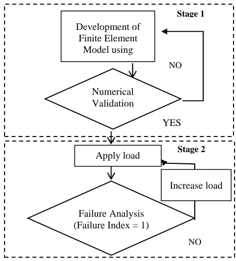
The method employed to achieve the objectives are divided into two stages. Stage one is numerical validation and stage two is failure analysis. Figure 1 below depicts the processes that were involved in the study.
Fig. 1 Processes involved for the validation and failure analysis of hybrid composite laminates
A. Numerical validation
The finite element results was obtained through the finite element programme, ANSYS v15 and validated by comparing the results obtained to the exact solution. The study replicates a research to allow to comparison of the
Stage 2
NO
Apply load
YES
Stage 1
Development of Finite Element
Model using ANSYS
Numerical Validation
NO
Failure Analysis (Failure Index = 1)
values of the finite element results on ANSYS v15 with exact values the research has already obtained [4]. A square symmetric cross ply [0/90/90/0] composite laminate plate with planar dimension of (a x b) with a thickness of ‘h’ was subjected under sinusoidal loading. The displacements and stress results were determined and recorded and compared to the results obtained[4]. Sixteen eight-nodded elements were utilized in modelling the laminated composite plates and two aspect ratios, a/h, of 10 and 100 were analysed. The geometry of the composite laminate plate is shown in Figure 2.
Fig. 2 Geometry of laminated composite plate
The sinusoidal loading applied to the composite laminate plate is [4],
(1)
Whereby . The
material properties of the composite laminate plate are tabulated in Table 1 [4].
TABLEI MATERIAL PROPERTIES
Properties Values
175 GPa
7 GPa
0.25
3.5 GPa
1.4 GPa
A simply supported (S) boundary condition was employed.
Fig. 3 Boundary condition for laminated composite plate
The maximum displacement and stress results were normalized as per these equations [4],
(2)
(1)
(2)
(3)
(4)
(5)
(6)
B. Failure Analysis
For the failure analysis, it was conducted on hybrid graphite (GR) and glass (GL) epoxy on ANSYS v15 as well. Three square hybrid composite plates of lamination scheme of [0/90/90/0] of [GL/GL/GL/GL], [GL/GL/GL/GR] and [GR/GL/GL/GL] was subjected to sinusoidal distributed loading to observe the first and last ply failure. The composite plates had a planar dimension of (a x b) and thickness of ‘h’. Twelve eight-nodded elements was used in modelling the hybrid composite laminate plates and aspect ratios, a/h. of 5,10,20,50 and 100 was simulated and analysed. The geometry of both the hybrid composite plates is as shown in Figure 4.
Fig. 4 Geometry of hybrid laminated composite plate
Sinusoidal loading was also applied to the composite plate is [4],
(7)
S
S
S
S
b
Element No. 12
x
y
a
b
Element No. 16
x
Whereby .
The material properties of the composite laminate plate of glass and graphite are tabulated in Table 2and Table 3.
TABLEII
MATERIALPROPERTYFORGRAPHITE/EPOXY
Elastic parameter Strength data
E1
E2 = E3
138 GPa 10.6 GPa
XT
XC
1450 MPa 1450 MPa
12= 23= 13 0.3 YT 51 MPa
G12=G23= G13 6.46 GPa
YC 250 MPa
S 93 MPa
TABLEIII
MATERIAL PROPERTY FOR GLASS/EPOXY
Elastic parameter Strength data
E1
E2 = E3
19.94GPa 5.83GPa
XT
XC
700.11 MPa 570.37 MPa
12 0.29 YT 69.67 MPa
G12 2.11GPa
YC 122.12 MPa
S 68.89 MPa
The boundary conditions applied for the analysis is the same as the one utilized in the numerical validation, which is simply supported. Failure was predicted using the built in failure theory and criterion in ANSYS, which is Maximum
Stress Failure Criteria. The results of the first and last ply failure loadings obtained from ANSYS, they were normalized using the following equations:
6 2
10
)
(
FPFload
S
ilure
FirstPlyFa
=
(10)6 2
10
)
(
LPFload
S
lure
LastPlyFai
=
(11)III.RESULTS AND DISCUSSION
A. Numerical Validation
The results of the percentage error of the normalized value against the exact value (Elasticity 3D) are tabulated in Table 4 and Table 5.
Based on the results obtained from the comparison of the finite element values and the exact values, the values obtained through ANSYS is considered accurate as the difference between the obtained value and the exact value is small, with less than 15% of error.
B. Failure Analysis
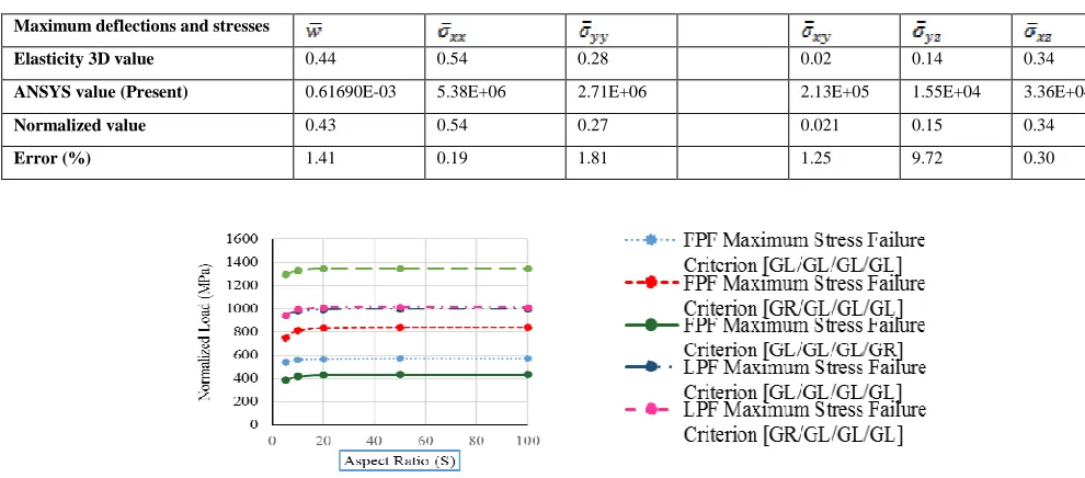
The normalized load for FPF and LPF in Table 4 to Table 5 are plotted against the respective aspect ratios in the graph in Figure 5.
TABLEIV
COMPARISON OF EXACT AND FINITE ELEMENT SOLUTION FOR MAXIMUM DEFLECTIONS AND STRESSES OF LAMINATED COMPOSITE PLATE WITH ASPECT RATIO, A/H, OF 10
TABLEV
COMPARISONOFEXACTANDFINITEELEMENTSOLUTIONFORMAXIMUMDEFLECTIONSANDSTRESSESOFLAMINATEDCOMPOSITE PLATEWITHASPECTRATIO,A/H,OF100
Fig. 5 Graph of normalized loads of FPF and LPF of hybrid laminated composite plates of different aspect ratios
Maximum deflections and stresses
Elasticity 3D value 0.74 0.56 0.40 0.03 0.20 0.30
ANSYS value (Present) 1.0571E-06 48271 39876 2528.8 2156.9 3058.9
Normalized value 0.74 0.48 0.40 0.02 0.21 0.30
Error (%) 0.42 13.65 0.56 8.04 10.05 1.62
Maximum deflections and stresses
Elasticity 3D value 0.44 0.54 0.28 0.02 0.14 0.34
ANSYS value (Present) 0.61690E-03 5.38E+06 2.71E+06 2.13E+05 1.55E+04 3.36E+04
Normalized value 0.43 0.54 0.27 0.021 0.15 0.34
From the results (Figure 5), it is observed that the lamination arrangement has significant effects on the overall strength of the hybrid composite. In the composite plate of lamination scheme of [GL/GL/GL/GR], FPF occurs at a smaller loading, compared to the FPF of the composite plate of lamination scheme of [GL/GL/GL/GL]. The FPF occurs at the fourth layer, which is the graphite layer. The addition of graphite does not strengthen but decreases the strength of the composite laminate, as the laminate with the graphite is the laminate that fails first. Even though the strength of the graphite fibres are much more stronger than the fibre strength of glass, the matrix strength of graphite in tension is considerably lower compared to the matrix strength of glass in tension, which accounts the FPF occurring in the graphite layer. This is the cause for the FPF loading of [GL/GL/GL/GR] composite laminate being lower than the FPF loading of [GL/GL/GL/GL] composite laminate.
In the composite plate of lamination scheme of [GR/GL/GL/GL] however, it was subjected to a much higher loading for it to exhibit FPF compared to the composite plate of lamination scheme of [GL/GL/GL/GL]. The FPF failure also occurred on the fourth layer, however in this case is the glass layer. Due to the matrix strength of glass in tension which is much higher than the matrix strength of graphite in tension, this attributes to the higher loading required for FPF to occur in the composite lamination scheme of [GR/GL/GL/GL].
However, when observing the LPF of composite plate of lamination scheme of [GL/GL/GL/GR] comparing it to the LPF of composite plate of lamination scheme [GL/GL/GL/GL], the former composite laminate was subjected to a much higher loading before it would exhibit last ply failure than the latter composite laminate. Even though both the composite laminates exhibit LPF at the same layer, which is the first layer which is glass, the addition of graphite in the former composite plate increases the strength considerably in accordance to the LPF.
For the LPF of composite plate of lamination scheme of [GR/GL/GL/GL] compared to the LPF of composite plate of lamination scheme [GL/GL/GL/GL], the former composite plate exhibited LPF on a slightly higher loading compared to the latter composite plate. In this case however, the addition of graphite only increases the strength slightly in accordance to LPF.
IV.CONCLUSION
This paper presented the utilization and application of finite element analysis using commercial software (ANSYS) to observe the effects of laminate arrangement on the failure behaviour of hybrid composite plates under transverse sinusoidal load. The results obtained successfully showed the loadings required for the hybrid composite plates to exhibit both first and last ply failure. From the result, it was exhibited that lamination schemes of glass and graphite in different arrangements can significantly change the strength of the laminated composite plate. A composite plate with a lamination scheme of [GL/GL/GL/GR] accelerated first ply
failure and delayed last ply failure, and a composite plate with a lamination scheme of [GR/GL/GL/GL] exhibited the opposite, whereby it delayed first ply failure and only slightly delayed last ply failure. This was done in comparison of a composite plate with a lamination scheme of [GL/GL/GL/GL]. Therefore, the failure behaviour of hybrid composites under sinusoidal loading varies with the lamination arrangement.
ACKNOWLEDGMENT
This work is supported by the Ministry of Higher
Education (MOHE) Malaysia via
RAGS/1/2015/TK0/FKM/03/B00104. Many thanks to Faculty of Mechanical Engineering, Universiti Teknikal Malaysia Melaka (UTeM) and Faculty of Mechanical Engineering, Universiti Teknologi MARA (UiTM) for the technical expertise and ANSYS software utilization.
REFERENCES
[1] R. M. Jones, "Mechanics of Composite Materials", CRC Press, 1998. [2] E.J. Barbero, "Introduction to Composite Materials Design", 3rd Ed,
CRC Press. 2017.
[3] F. C. Campbell, “Introduction to Composite Materials,” 2010. [4] P. Tasneem, A.-Z. Khalid, and F. K. S. Al-Jahwari, “Effects of
Boundary Conditions in Laminated Composite Plates Using Higher Order Shear Deformation Theory,” 2010.
[5] G. Czél, M. Jalalvand, and M. R. Wisnom, “Demonstration of pseudo-ductility in unidirectional hybrid composites made of discontinuous carbon/epoxy and continuous glass/epoxy plies,”
Compos. Part A Appl. Sci. Manuf., vol. 72, pp. 75–84, 2015.
[6] A. H. Samsudin, A. K. Hussain, and J. Mahmud, “Deformation and Failure Analysis of Symmetric and Anti- Symmetric Graphite / Epoxy Laminate due to Variations in Fiber Orientation,” vol. 10, no. 17, pp. 7336–7344, 2015.
[7] K. Bakshi and D. Chakravorty, “First ply failure study of thin composite conoidal shells subjected to uniformly distributed load,”
Thin-Walled Struct., vol. 76, pp. 1–7, 2014.
[8] A. Zucchelli, G. Minak, and F. Cesari, “Probabilistic first-ply failure analysis of a laminate in composite material,” Int. J. Eng. Model., vol. 13, no. 1–2, pp. 35–40, 2000.
[9] L. A. and S. B. N. Gadade Appaso M, “Stochastic First-Ply Failure Analysis of Laminated Composite Plates under in Plane Tensile Loading Stochastic First-ply Failure Analysis of Laminated Composite Plates,” vol. 747, no. December, pp. 269–272, 2015. [10] N. Rahimi, M. Musa, A. K. Hussain, and J. Mahmud, “Finite
Element Implementations to Predict the Failure of Composite Laminates Under Uniaxial Tension,” Adv. Mater. Res., vol. 499, pp. 20–24, 2012.
[11] S. T. Agusril, N. M. Nor, and Z. J. Zhao, “Failure Analysis of Carbon Fiber Reinforced Polymer (CFRP) Bridge Using Composite Material Failure Theories,” Adv. Mater. Res., vol. 488–489, no. 1, pp. 525– 529, 2012.
[12] J. Zhu, J. Wang, and L. Zu, “Influence of out-of-plane ply waviness on elastic properties of composite laminates under uniaxial loading,”
Compos. Struct., vol. 132, pp. 440–450, 2015.
[13] H. T. Hu, W. P. Lin, and F. T. Tu, “Failure analysis of fiber-reinforced composite laminates subjected to biaxial loads,” Compos.
Part B Eng., vol. 83, pp. 153–165, 2015.
[14] A. Rashedi, I. Sridhar, and K. J. Tseng, “Fracture characterization of glass fiber composite laminate under experimental biaxial loading,”
Compos. Struct., vol. 138, pp. 17–29, 2016.