INTRODUCTION
Improvements in manufacturing techniques and production engineering along with the grow-ing markets in automotive, aviation and machine industries cause the need for shortening the total production time of parts and components used in these branches [10, 11]. It also creates new require-ments regarding the processes that are inseparable part of production process, which include quality control or production supervision and monitoring [7, 12]. The trends regarding decrease of measure-ment or inspection time are also clearly visible in these fields [4, 9]. One of the relatively novel systems that were developed because of the above-mentioned reasons are the CMM probe heads that are used in so called five-axis measuring coordi -nate systems. The main feature that makes them different from typical probe heads is the possibil -ity of continuous articulation, thanks to which the five-axis measuring systems are capable of performing measurements using only probe head
rotary movements [3]. This improvement gives possibility for reduction of measurement time, which is achieved because movements of heavy and large machine parts are replaced by the rapid movements of probe head rotary axes. The use of this type of probe heads helps also in reduction of CMM dynamic errors related to repeated starting and stopping of the machine movements between probing of measuring points.
Of course, apart from numerous advantages, probe heads used on five-axis measuring systems have some drawbacks [1, 5]. They include necessi-ty of performing long-time calibration of the head itself and all probes that are used during measure-ments, necessity of application of complicated er-ror correction systems and metrological software that is compatible with that kind of probe heads. All of the above mentioned treatments are used for reducing the inaccuracies of probe heads, in order to fully use its functionalities.
Recently, it was also noted that measurement of workpieces being the solids of revolution with
ANALYSIS OF MEASURED WORKPIECE’S FORM ERRORS INFLUENCE
ON THE ACCURACY OF PROBE HEADS USED ON FIVE-AXIS
MEASURING SYSTEMS
Wiktor Harmatys1, Adam Gąska1, Maciej Gruza1, Piotr Gąska1, Jerzy Sładek1
1 Cracow University of Technology, Laboratory of Coordinate Metrology (M-10), Mechanical Engineering Faculty,
al. Jana Pawła II 37, 31-864 Kraków, Poland, e-mails: [email protected], [email protected], [email protected], [email protected], [email protected]
Research Journal
Volume 11, Issue 4, December 2017, pages 305–310
DOI: 10.12913/22998624/80893 Research Article
ABSTRACT
The five-axis measuring systems are one of the most modern inventions in coordinate measuring technique. They are capable of performing measurements using only the rotary pairs present in their kinematic structure. This possibility is very useful because it may cause significant reduction of total measurement time and costs. However, it was noted that high values of measured workpiece’s form errors may cause significant reduction of the accuracy of a five-axis measuring system. The investigation on the re -lation between these two parameters was conducted in this paper and possible reasons of decrease in measurement accuracy was discussed on the example of measurements of workpieces with form errors ranging from 0,5 to 1,7 millimetre.
Keywords: articulating probe head, five-axis system, accuracy, CMM Received: 2017.10.25
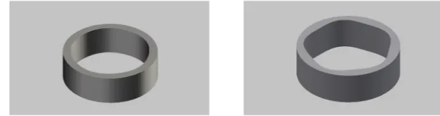
Fig. 1. CAD models of the developed material standards: a) with less significant form deformations, b) with more significant form deformations
The idea of conducting research presented in this paper was conceived because of authors’ experiences with the use of PH20 probe head. It was noted that during measurements of some workpieces, the results obtained using the above-mentioned probe head was visibly worse than us-ing probe heads that function on machines work-ing in traditional three-axis mode. The prelimi -nary analyses done by the authors showed that this situation occurs primarily for the measured workpieces whose form errors reach tenth parts of millimetre.
In order to prove it, the experimentation was planned. It consists of four stages: modelling of material standards in shape of cylinders burdened with the predetermined values of form errors, manufacturing of them, calibration measurements performed on high accuracy CMM, measurement of manufactured standards at CMM equipped with PH20 probe head and comparison of cali -bration results with results of measurements done using PH20 probe.
Modelling of material standards
The cylinder-shaped material standards were modelled in chosen 3d CAD software. There were two types of standards prepared. The first one (Fig. 1a) was prepared using function pre-sented in equation (1) defined in polar coordinate system, for a changing in range (0°,360°) :
𝑦𝑦 = 20 + 0,25 ∗ cos5𝛼𝛼
(1)𝑦𝑦 = 20 + 0,8 ∗ cos5𝛼𝛼
(2) so the nominal form deviation of this material standard equals to 1,6 mm.Manufacturing of material standards
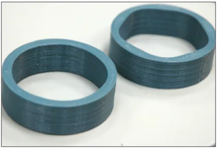
Models presented in previous section were used for printing the material standards using Fused Deposition Method (for more informa-tion on this method see [2]). Printer that was used in this process was the “Aurora 3d” printer described in [6]. ABS was the material used as a filament. Figure 2 presents the process of print -ing the material standards and Figure 3 presents manufactured standards.
Calibration of prepared standards
Manufactured material standards were cali-brated on PMM 12106 machine whose MPE er-rors are given by equation (3):
𝐸𝐸
0,𝑀𝑀𝑀𝑀𝑀𝑀= 0,8 + 2,5 ∗
1000𝐿𝐿, mm
(3)which were subject to calibration and calibrated workpiece. The temperature in CMM measuring volume during calibration was in the range 20 ± 0,1°C. Calibration measurements and mounting of the workpieces were presented in Figure 4.
Table 1 presents the results of calibration for both material standards.
Measurements of considered workpieces There were 3 workpieces selected for mea-surements: two material standards presented in previous sections of these paper and standard ring with diameter of 20 mm. Measurements were performed using Zeiss WMM 850s machine equipped with PH20 probe head. Material stan -dards were measured in order to prove existence
of significant accuracy loss during measurements of workpieces with high levels of form errors, while the standard ring was measured in order to prove that in a situation in which the workpieces with low values of form errors are measured the accuracy loss is not recorded. In each case, the same number and distribution of measuring points as in case of calibration measurements was used. The temperature in CMM measuring volume dur-ing measurements was in range 19,7 – 20,2 °C.
The results obtained from measurements of all considered workpieces performed using PH20 probe head were compared with the results from calibration measurements. Measurements per-formed on Zeiss WMM machine are presented in Figure 5. The results of performed measurements and comparisons are shown in section 3.
RESULTS OF MEASUREMENTS
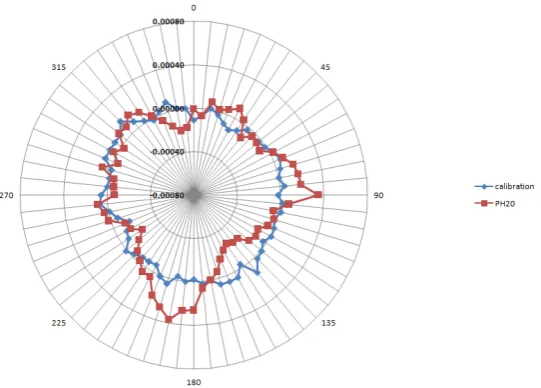
Figures 6–8 present the results of measure -ments and comparisons that were described in section 2. All errors presented in these figures are mean radial errors calculated from 10 repetitions of considered measurement.
Form errors identified for standard ring by calibration measurements equaled to 0,0003 mm and by measurements using PH20 probe head to 0,0006 mm. Deviation between these two values was 0,0003 mm. The biggest absolute value of difference between er,PMM and er,PH20 was Fig. 2. Printing of material standards on “Aurora 3d”
FDM printer Fig. 3. Material standards prepared using 3d printer
Table 1. Calibration results for both manufactured material standards, eq. (1) means that the material standard was modelled using equation (1), while eq. (2) means that it was modelled using equation (2)
Workpiece Form deviation, mm Expanded uncertainty, mm
Material standard eq. (1) 0,5885 0,0004
Material standard eq. (2) 1,6806 0,0004
achieved for a equal to 90 º and equaled 0,0004 mm (where a is the angle of approach at a certain point – it is consistent with a defined in equa -tions (1) and (2), er,PMM is the mean radial error in direction defined by a for calibration measure-ments and er,PH20 is the mean radial error in direc-tion defined by a for measurements performed using PH20 probe head).
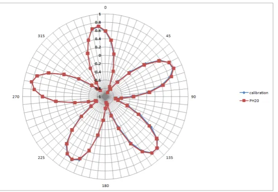
Form errors identified for material standard modelled using equation (1) determined by cali-bration measurements equaled to 0,5885 mm and by measurements using PH20 probe head to 0,5709 mm. Deviation between these two values was -0,0176 mm. The biggest absolute value of difference between er,PMM and er,PH20 was achieved for a equal to 191,25 º and equaled 0,0325 mm.
Form errors identified for material standard modelled using equation (2) determined by
cali-The results presented in section 3 prove the existence of accuracy loss during measurements of workpieces with high level of form error val-ues (form errors valval-ues at the level of tenth parts of millimetre and bigger) performed using PH20 probe head. The accuracy loss is not observed for measurements of workpieces with lower values of form errors.
However, it is hard to determine unambiguous relation between the values of workpiece’s form errors and values of five-axis measurement errors corresponding to them. In case of both material standards that were measured the absolute mean value of difference between the results of calibra -tion measurements and measurements performed using PH20 probe head was equal to about 0,02 mm. However, in case of artifact with smaller form errors, identification of their value using PH20 probe head gave smaller values than cali -bration, which is opposite to the measurements of artifact with bigger form errors, for which the values of form errors identified using PH20 probe head was bigger than in case of calibration. Hav -ing in mind the results obtained dur-ing measure-Figure 5. Measurements of material workpieces and
standard ring performed on Zeiss WMM 850s ma-chine equipped with PH20 probe head
ments of standard ring, in which the difference in form errors values for both calibration and PH20 measurements was almost zero, it should be concluded that the relation between the values of workpiece’s form errors and values of five-axis measurement errors corresponding to them does not have a linear character. More detailed investi-gations on that matter will be undertaken in near future by the authors.
As a possible cause of the observed accuracy loss, too far simplifications of algorithms used by the metrological software may be taken. Form er-rors in workpieces cause that the stylus mounted on probe head travels further or closer in regard
to theoretical data of measured feature. In case of probe heads used on five-axis measuring sys -tems it also means that the rotation angle in one of probe head’s axes reaches higher or lower values than in case of measurement of points generated for nominal feature. It causes that the tip of sty-lus hits the surface of measured object in different point that is expected for generated measurement code. In this case, the radial correction of stylus tip may be done in slightly different direction that it should be and it may cause additional errors.
Identified accuracy loss is at the level of 25 micrometres for workpieces whose form errors are at the level of 1,6 mm. So the rate of rela-Figure 7. Graphical comparison of the results of measurements of material standard with nominal values of form
error equal to 0,5 mm.Values on vertical axis gives mean radial error in mm, values on circumference of graph gives values of a angle in degrees
Figure 8. Graphical comparison of the results of measurements of material standard with nominal values of form error equal to 1,6 mm. Values on vertical axis give mean radial error in mm, values on circumference of graph
Acknowledgments
Reported research was realized as part of a project financed by National Science Centre, Po -land, grant no. 2015/17/D/ST8/01280.
REFERENCES
1. Dobosz, M.,Woźniak, A. CMM touch trigger probes testing using a reference axis. Precision En -gineering, 29, 2005, 281–289.
2. Fudali P., Witkowski W., Wydrzyński D. Compari -son of geometric precision of plastic components made by subtractive and additive methods. Ad-vances in Science and Technology Research Jour-nal, 7(19), 2013, 36–40.
3. Gąska A., Gąska P., Gruza M. Simulation Model for Correction and Modeling of Probe Head Errors in Five-Axis Coordinate Systems. Applied Scienc -es, 6(5), 2016.
4. Gaska P., Gaska A., Gruza M. Challenges for mod -eling of five-axis coordinate measuring systems.
Press, 2012.
8. ISO 15530–3:2011 – Geometrical product speci -fications (GPS) – Coordinate measuring machines (CMM): Technique for determining the uncertainty of measurement – Part 3: Use of calibrated work -pieces or measurement standards.
9. Jóźwik J., Czwarnowski M., Angular positioning accuracy of rotary table and repeatability of five-axis machining centre DMU 65 MONOBLOCK. Advances in Science and Technology Research Journal, 9(28), 2015, 89–95.
10. Mayer J.R.R., Mizanur Rahman M., Los A. An un -calibrated cylindrical indigenous artefact for mea-suring inter-axis errors of a five-axis machine tool. CIRP Annals, 64(1), 2015, 487–490.
11. Pashaki P.V., Poulja M. Volumetric error compen-sation in five-axis CNC machining center through kinematics modeling of geometric error. Advanc-es in Science and Technology RAdvanc-esearch Journal, 10(30), 2016, 207–217.